CS 25-OI-vers. 2.5 gb. 18. 04. 16 3
Table of contents
1.0.0 EC Declaration for Incorporation (Document original) ....................................... 5
1.1.0 According to: 2006/42/EC .............................................................................. 5
2.0.0 Module Information............................................................................................ 6
2.1.0 Transport and storage (packing and unpacking)............................................ 6
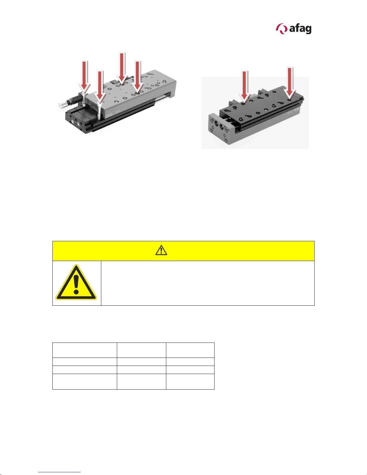
2.1.1 Possibilities of fastening the CS 25................................................................ 7
2.1.2 Centering bushings and hole matrix............................................................... 7
2.1.3 Tightening moments for screws ..................................................................... 9
2.1.4 Slide unit load factors................................................................................... 10
2.1.5 Preferred combinations for CS 25................................................................ 11
3.0.0 Montage Instructions ....................................................................................... 12
3.1.0 The manufacturer: Afag Automation AG................................................... 12
3.1.1 Symbols....................................................................................................... 12
3.1.2 General description...................................................................................... 13
3.1.3 Description of the CS 25 module ................................................................. 14
3.1.4 Scope of supply ........................................................................................... 15
3.1.5 Intended use ................................................................................................ 15
3.1.6 Warranty ...................................................................................................... 16
3.1.7 Areas of application...................................................................................... 16
3.1.8 Dimension CS 25......................................................................................... 17
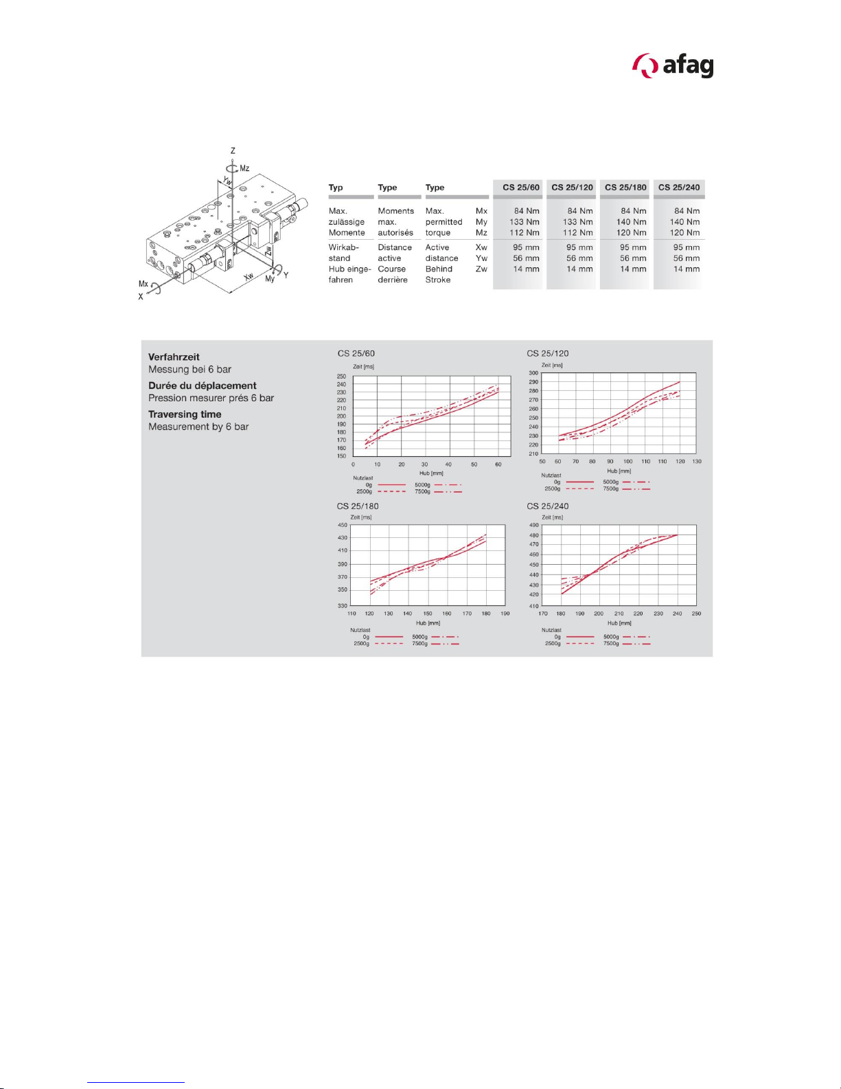
3.1.9 Technical data.............................................................................................. 18
3.2.0 Pneumatic connections................................................................................ 19
3.2.1 Preparation for start-up................................................................................ 20
3.2.2 Setting the shock absorbers and the stop screws........................................ 21
3.2.3 Inquiry of the sensors................................................................................... 22
3.2.4 Accessories.................................................................................................. 22
3.2.5 Fitting the proximity switch in the module grooves....................................... 23
3.2.6 Fitting the initiator......................................................................................... 24
3.2.7 Check of the final position in the total stroke range...................................... 25
3.2.8 Start-up of the CS 25 Compact Slide........................................................... 26
3.2.9 Optional ZA intermediate stop for the CS 25................................................ 26
3.3.0 Attaching the ZA intermediate stop to the CS 25......................................... 27
3.3.1 Attaching the ZA intermediate stop to the CS 25 module............................. 28
3.3.2 Fine adjustment of the stop screw with shock absorber............................... 29
3.3.3 Operating sequence of the intermediate position when extending............... 30