BEP Marine CZONE User manual

Wireless function:
Button 1
Pressing button 1 will turn on engine and house batteries.
Button 2
Pressing button 2 will turn off engine and house batteries.
Button 3
When the batteries are turned on press button 3 and all of the lights will
turn on press button 3 again and the lights will shut off.
Button 4
Pressing button 4 will energize the lights used for night time running and
shut off lights not used for operating the boat at night.
Helm Mode Button on Dash Panel:
Pressing the mode switch will cycle thru several different modes. The first
mode turns on all of the lights. The second mode puts the boat into night
running mode. The third press is the Mood lighting mode. The fourth press
will shut off all of the lights.
Console Button at DC Panel:
Press the house or engine button to turn on or off the house or engine
battery switch.
https://www.boat-manuals.com/

Motorized Battery Switch:
The Motorized Battery Switch has two modes of operation.
Auto and Manual. There is a LED located on the battery switch indicating
Battery Switch status.
Manual Operation:
The automatic operation of the battery switch
can be overridden at any time by depressing the control knob and
turning clockwise towards the “Man On” position or counter clockwise
towards the “Man Off” position. During the time that the Battery switch is
in “Man On” mode, the “Man On” LED is illuminated.
Auto Operation:
The battery switch moves from a state of “Auto Off” to “Auto On” when
either the wireless remote button 1 is pressed or the button at the DC
panel is pressed. During the time that the battery switch is in “Auto On”
mode, the “Auto On” LED is illuminated. Auto operation of the Battery
Switch is not possible while in manual mode. If auto operation is
attempted, the LED will flash for 3 seconds then stop. Knob must be
returned to “Auto Off” before normal auto operation can continue.
Auto Mode LED Indications:
LED OFF: Battery switch is off
LED ON: Battery switch is on
LED FLASHING: LED flashes whilst moving
between auto on and auto off.
LED Rapid Flash: On 0.1 sec & Off 0.1 Sec:
Voltage is outside specification i.e. Less than
8 Volts or greater than 30 Volts
Manual Mode LED Indications:
LED OFF: Battery Switch is off
LED ON: Battery Switch is on
!WARNING: Depress
knob while turning or
the switch motor could
be damaged
https://www.boat-manuals.com/
Product description:
The CZone Display module (DI) is the CZone systems user interface, it has the ability to control DC circuits, display important on board
systems information and can be used to set all Zone parameters both for initial installation and future systems maintenance
Suitable to use as the main systems controller/display at the helm or nav station or as a secondary display in an owners cabin or engine room
Simple connection, power and NMEA
• 3.5” Transflective QVGA LCD
• IpX7
• Rotary Knob for easy menu navigation
• Simple UI
• Power consumption @12V: 180mA (standby 130mA)
Dimensions:
H 105mm (4”3/32) x W165mm (6”7/16) x D 62mm
(2”13/32)
Weight:
374g
DC Power Meter:
• Displays Voltages of multiple battery banks includes
low and high voltage alarms
• Displays charge and discharge (amps) of multiple
battery banks
• Displays battery capacity in ampere hours and %
charge/discharge, includes low ampere hour alarm
AC Power Meter:
• Displays multiple line voltages (230 and 110V),
includes high and low voltage alarm
• Displays AC line frequencies, includes High and low
frequency alarm
• Displays AC power consumption in kW (calculation
uses power factor for true RMS)
DI features:
Fluid level display:
• Displays multiple tank levels and multiple fluid types
• Fuel (Diesel and Gas)
• Fresh water
• Black water
• Grey water
Switching thresholds can be set for tank levels to raise alarms or to
control an output i.e. a ballast pump can be automatically con-
trolled via the ballast water level
Switching channel control:
All DC control circuits can be toggled on or off
Systems in operation:
• Displays operation of circuits of interest ie Bilge pumps,
engine room lights etc
• Displays systems faults and alarm conditions
(programmable)
• Repeater for other NMEA 2000 broadcasted data
EMC ratings:
• IEC EN 60945
• IEC EN 61000
• FCC Class B
• ISO 7637 - 1 (12V Passenger cars and light
commercial vehicles with nominal 12 V supply
voltage - Electrical transient conduction along
supply lines only)
• ISO 7637 - 2 (24V Commercial vehicles with nominal 24 V
supply voltage - Electrical transient conduction along supply
lines only)
• IEC Standards for indirect lighting strikes
Inputs:
Network, NMEA 2000
5 – 35V DC
Display Interface (DI)
For more information contact BEP | ph: +64 9 415 7261 | email: [email protected] | www.bepmarine.com
https://www.boat-manuals.com/
Operation
For more information contact BEP | ph: +64 9 415 7261 | email: [email protected] | www.bepmarine.com
Main Screen Monitoring Page
DC Monitoring Tank Monitoring
AC Monitoring Main Control Page
https://www.boat-manuals.com/
Control Page Detailed Control Page
Settings Menu Alarms Page
Operation
For more information contact BEP | ph: +64 9 415 7261 | email: [email protected] | www.bepmarine.com
https://www.boat-manuals.com/

Pictorial Overview
Menu – returns user to main menu page (as shown below)
ESC – Escape key, returns to previous screen
Ent – Enter key, navigates to next screen or confirms prompt
Rotary Knob – Scrolls cursor bar up and down through menu lists,
used to navigate alpha numeric lists in configuration pages
Off (-) – Turns circuit off, decreases values in set up screens such as
backlighting level
ON (+) – Turns circuits on, Increases values in set up screens such as
backlighting level
Power Key – Turns display off and on
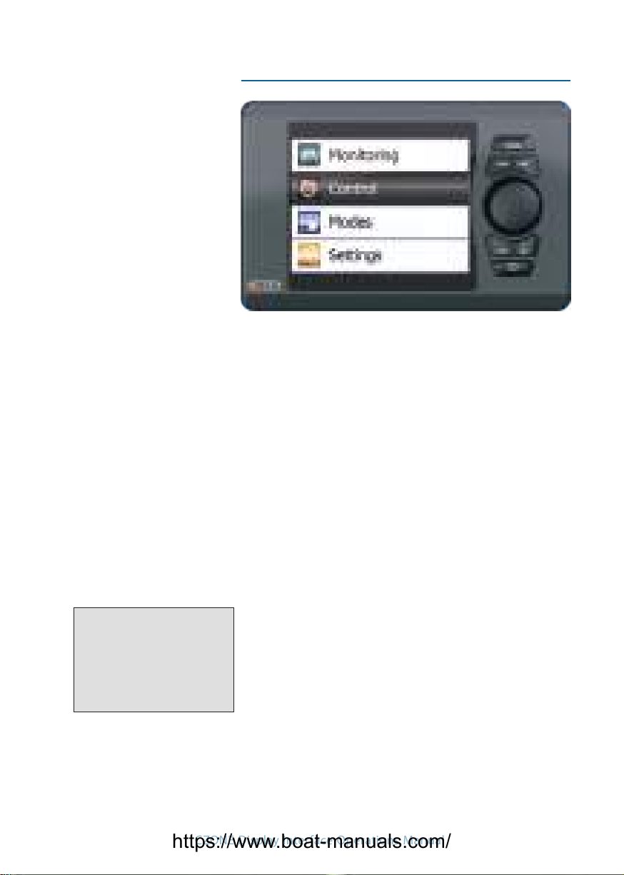
Main Menu page
NMEA 2000 connector Power connector
Top View (mounted in panel)
Connections
For more information contact BEP | ph: +64 9 415 7261 | email: [email protected] | www.bepmarine.com
https://www.boat-manuals.com/
Display Interface Operation Manual
. . . . . Leading By Design
https://www.boat-manuals.com/

IMPORTANT
BEP Marine strives to ensure all information is correct at the time of printing. However,
BEP Marine reserves the right to change any features and specications of either the operation
of the device, or the documentation of the device, without notice.
Translations: In the event that there is a dierence between a translation of this manual and the
English version, the English version should be considered the ocial version.
FCC Statement: This device complies with the limits for a Class B digital device, pursuant to
part 15 of FCC rules. These rules pertain to reasonable protection from harmful interference in
a normal installation. This equipment generates extremely low levels of radio frequency energy
which should not interfere with normal radio equipment if installed properly. If interference is
detected and attributed to this device, you could try to:
» Re-orient or relocate the receiving antenna
» Separate the equipment and the receiver
» Isolate circuit output between the device and the radio
» Contact an experienced technician or dealer to help
It is the owner’s sole responsibility to install and operate the device in a manner that will not
cause accidents, personal injury or property damage.
Copyright: This document is copyright 2008 under the Creative Commons agreement. Rights
are granted to research and reproduce elements of this document for non-commercial purposes
on the condition that “BEP Marine” is credited as the source. Electronic re-distribution of the
document in any format is restricted, to maintain quality and version control.
https://www.boat-manuals.com/

3
CZONE Display Interface Operations Manual
Contents
1. Overview . . . . . . . . . . . . 5
Display Interface 6
Powering the DI 7
Screen Features 7
2. Navigation Conventions . . . . . . . 9
‘Spin box’ Data Entry 9
3. Directory Tree . . . . . . . . . 10
MONITORING 10
CONTROL 11
MODES 11
SETTINGS 12
4. Specifications. . . . . . . . . . 17
5. Contact Addresses . . . . . . . . 18
https://www.boat-manuals.com/

4
CZONE Display Interface Operations Manual
Overview1.
A CZONE network is an NMEA 2000-compliant
CAN-based system. With a maximum of
40 possible reporting interfaces in a single
‘backbone’ network, the size of the network
you want is virtually limitless: for vessels with
larger electrical systems extra backbones can
be attached.
Because there is no centralized processing
facility, a CZONE network is not crippled with
the collapse of any one unit.
Your main connection with each CZONE
interface throughout your vessel is the Display
Interface, or DI. All other interfaces are normally
configured at the time of installation, and re-
configured very occasionally in your vessel’s
life. Once installed, your DI becomes the main
way you can oversee and configure the entire
system. But like any other interface, removing
the DI from the network does not cripple the
network: all other interfaces work with each
other normally.
This manual is aimed at the intermediate and
experienced skippers. It is assumed you have
basic knowledge of how your vessel already
operates, basic electrical knowledge, and
have had some basic experience with the
conventions of computer equipment.
https://www.boat-manuals.com/
5
CZONE Display Interface Operations Manual
Display Interface
MENU Jumps to the Main Menu
ESC Returns to last screen viewed.
ENT Moves to the screen selected.
Dial Primarily used for menu navigation;
sometimes used in configuration
screens for quickly selecting from a
large set of values.
–/OFF Decrease a value; disable an interface
channel.
+/ON Increase a value; enable an interface
channel.
POWER Activates/Deactivates the DI.
NOTE F
The POWER Button has no
effect on the network. Its only
use is to activate and deactivate
the DI’s screen power.
https://www.boat-manuals.com/

6
CZONE Display Interface Operations Manual
Powering the DI
Press»POWER.
Press»MENU.
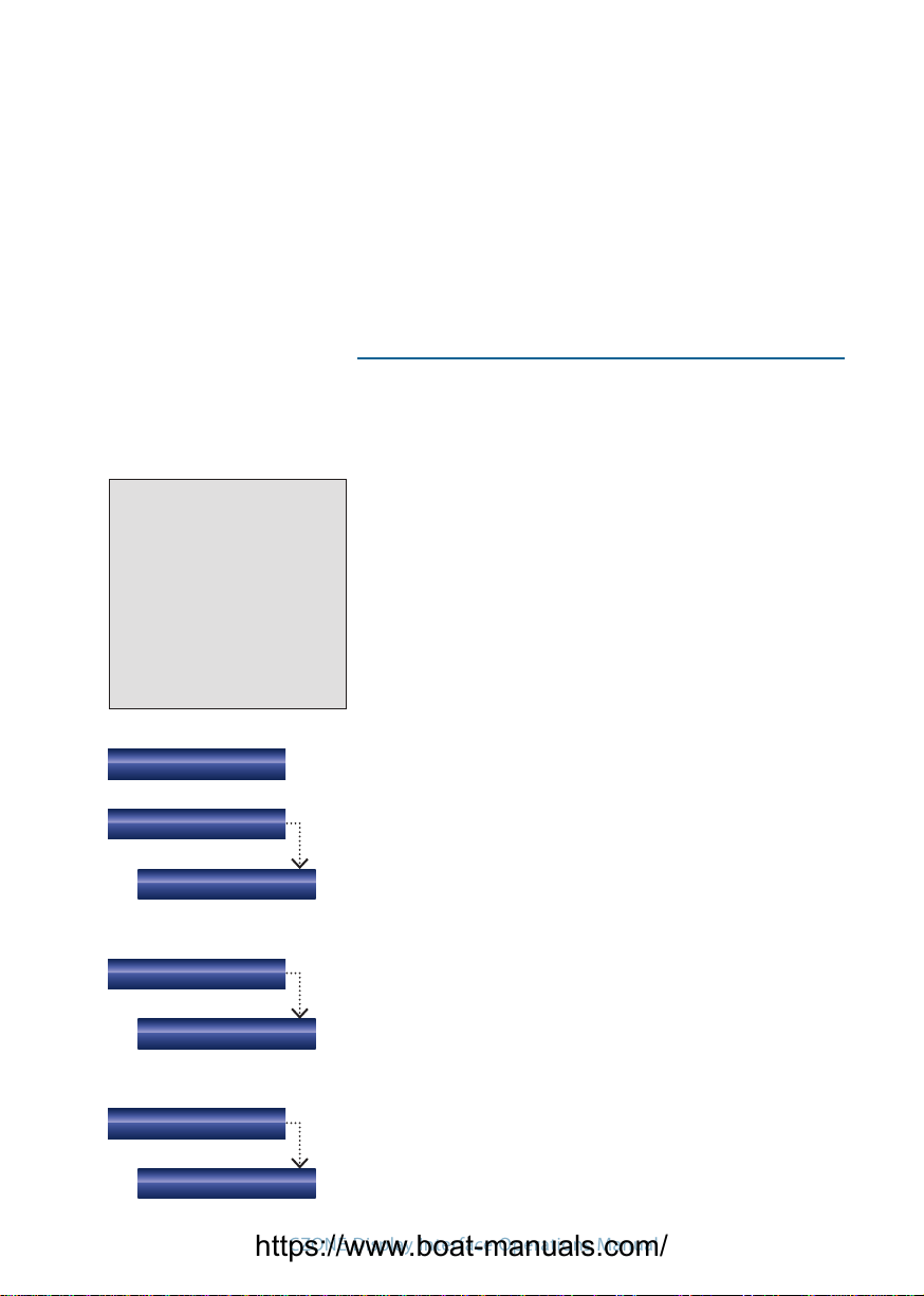
Screen Features
Each screen contains one of several features:
A menu selection to more specific controls.
The status of a group of CZONE measurements.
The status of a specific CZONE measurement.
https://www.boat-manuals.com/

7
CZONE Display Interface Operations Manual
A list of checkboxes.
A ‘spin box’ of multiple variables. (The Dial is
used to change values.)
https://www.boat-manuals.com/

8
CZONE Display Interface Operations Manual
Option 3
Option 2
Option 1
Sub-Option A
Sub-Option B
Target Screen
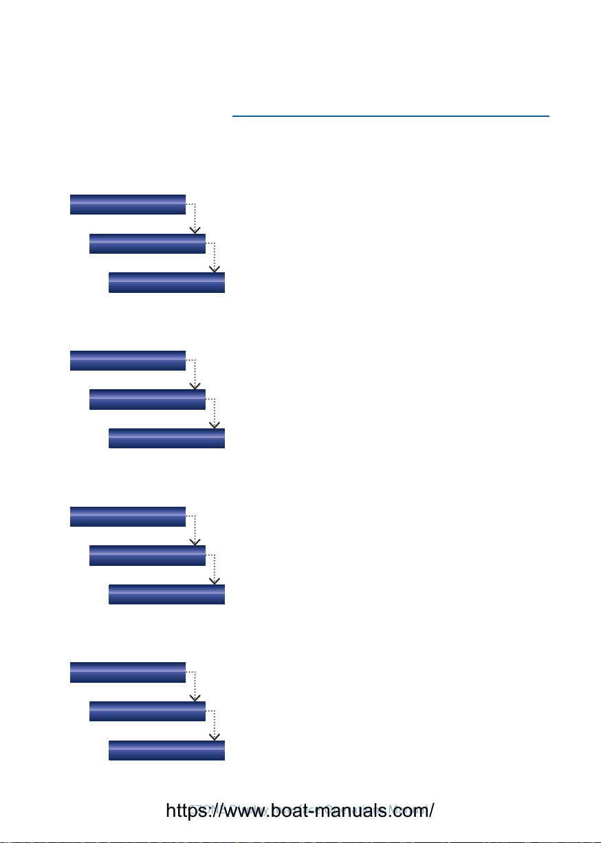
Navigation Conventions2.
The use and operation of the DI for your
CZONE network is extremely easy. For the vast
majority of use:
Use the»Dial to select an on-screen option.
Press»ENT to open the selected option.
Repeat the Dial - ENT operation until you
reach your target screen.
Press»ESC to step back to the last screen.
Press»MENU to return to the main menu.
Use»– OFF / + ON to decrease or increase
values.
ENT
‘Spin box’ Data Entry
In some system configurations, the Dial is used
for ‘spin box’ entry, either to select an item
from a long list of values, or text entry.
If a target screen has a spinbox field, rolling»
the Dial cycles through the values available,
or the alphabet of the currently active
character.
If the currently active character is part of a»
preset text value, the value is filled in.
– OFF»moves the text cursor left one space.
+ ON»moves the text cursor right one space.
ENT» sets the entry and shows the next
screen.
Spin boxes
Back (–) Forward (+)
https://www.boat-manuals.com/
9
CZONE Display Interface Operations Manual
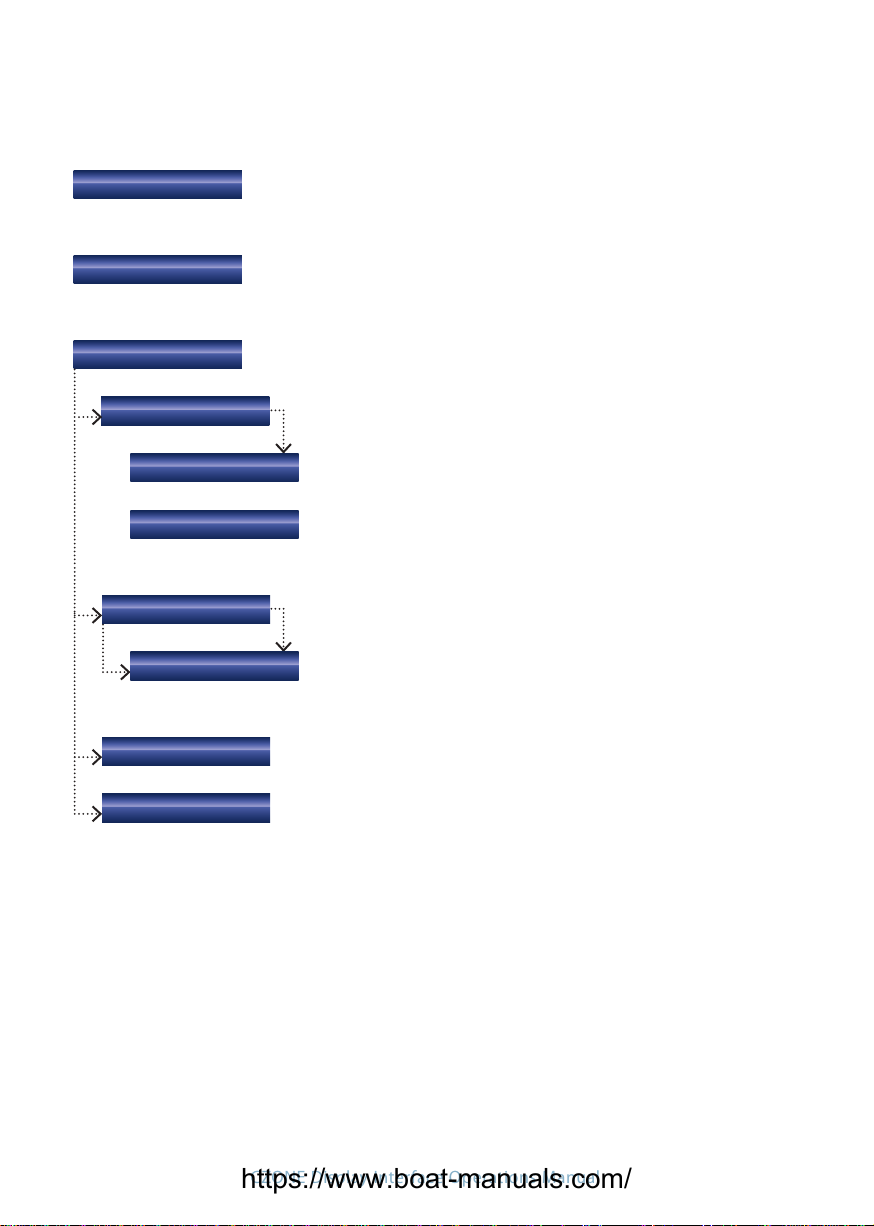
Directory Tree3.
Voltage (V), Current (A), Real Power (W), Frequency (Hz)
AC Monitoring
AC Power (all)
AC Power (1)
Tanks
DC Monitoring
Tanks (all)
DC Power (all)
Tank (1)
DC Power (1)
Data
Data (all)
Data (1)
Voltage (V), Current (A), Time Remaining (A/h), Charge State (%)
MONITORING
Tank level (%, level [L/Gal], capacity [L/Gal])
The Data collections appearing in this screen are congured in
Settings.
The Monitoring section of the DI provides quick
reference general and detailed views of circuit
status, tank levels, AC and DC voltages and
many other parameters throughout the vessel.
https://www.boat-manuals.com/

10
CZONE Display Interface Operations Manual
Systems in Operation displays lists of all circuits that are active
at that moment.
The list appearing in this screen is congured during the initial
set up.
Pressing ENT displays circuit-relevant info.
Systems in Operation
Circuits Groups
Circuit Group (1)
Selection (Detail)
Circuit Groups
Circuit Group (1)
(Selection Detail)
The groups appearing in this screen are congured during the
initial set up.
Each item in this screen’s list can be selected with the Dial,
then adjusted with the – OFF/+ ON keys.
Pressing ENT displays circuit-relevant info.
The Control section of the DI allows you to turn
circuits on and off, or in the case of certain
lights, dim them to different levels.
CONTROL
MODES
The Modes function allows multiple circuits
to be turned on at once according to certain
predetermined modes. For example you walk
onto your boat and activate the Cruise mode,
turning on all the circuits required for complete
operation of the boat. When you leave the boat
you can then select System Off mode which
shuts down all non 24Hr circuits.
Modes (all)
https://www.boat-manuals.com/
11
CZONE Display Interface Operations Manual
Alternatively you can select Dock mode which
once again turns all non-24hr circuits off
except for the refrigeration circuits. (These
are just examples; user-specific modes can be
configured by a technician.)
SETTINGS
Backlight
About
Key Beeps
Level
On/Off/Tick On
The Settings section is where you set all
operating tolerances, calibration, preferences
and alarm triggers.
Your CZONE network is normally installed with
default settings for you. However, customizing
your network to suit how you operate your
vessel is all part of the flexibility and identity of
A CZONE network.
WARNING F
Changing calibration or
dimensional values may
compromise the safety and
efficiency of your vessel. Please
ensure your alterations do
not misrepresent your vessel’s
operational limits.
Hold – OFF / + ON to adjust DI’s backlight level.
Units
Volume
Press + ON to set functionality.
Select between Liters and US Gallons.
Displays software version installed on the DI and dipswitch
setting
https://www.boat-manuals.com/
12
CZONE Display Interface Operations Manual
Text Size
Rotary Direction
Calibration
Choose a text size for your DI.
Choose a direction for which way the dial will increase values.
DC Monitoring
(User batteries)
Set Battery Full
The Calibration subsection allows you to set certain parameters
for your CZONE system.
Voltage (V), Current (A)
Each battery may be dened, calibrated or reset to defaults.
Yes sets the battery level to Full
Allows you to select what parameters are displayed in the
Monitoring - Data page
Press - OFF / + ON to select if that parameter is displayed.
Displays a list of all congured modules showing their state
(Online or Oine) and dispwitch setting.
By entering a password the parameters of your CZONE system
can be adjusted to allow additions or modications. Only
trained technicians should carry out this work.
Custom Data
Network
System Cong
Monitoring Parameters
https://www.boat-manuals.com/

13
CZONE Display Interface Operations Manual
Display Interface
Dimensions: H x W x D - 105 x 165 x 62 mm
4 3/32 x 6 7/16 x 2 13/32 in
Weight: 374 g
DC Power Meter:
Displays voltages of multiple battery banks with low and high voltage alarms;
charge and discharge (amps) of multiple battery banks; battery capacity in ampere
hours and % charge/discharge; includes low ampere hour alarm.
AC Power Meter:
Displays multiple line voltages (230 and 110 V with low and high voltage alarms);
AC line frequencies (includes high and low frequency alarm for each); AC power
consumption in kW (calculation uses power factor for true RMS).
Fluid level display:
Displays multiple tank levels/multiple fluid types such as Diesel/Gas/Fresh water/
Black water/Grey water; switching thresholds can be set for tank levels to raise
alarms or to control an output i.e. a ballast pump can be automatically controlled via
the ballast water level.
Switching channel control:
All DC control circuits can be toggled on or off, dimmed or motors reversed.
Systems in operation:
Displays operation of circuits of interest ie Bilge pumps, engine room lights etc;
systems faults and alarm conditions (programmable); Repeater for other NMEA 2000
broadcasted data.
Inputs:
Network, NMEA 2000, 5 – 35 V DC
EMC ratings:
IEC EN 60945, IEC EN 61000, FCC Class B.
ISO 7637 - 1 (12 V Passenger cars and light commercial vehicles with nominal 12 V
supply voltage - Electrical transient conduction along supply lines only).
ISO 7637 - 2 (24 V Commercial vehicles with nominal 24 V supply voltage - Electrical
transient conduction along supply lines only).
IEC Standards for indirect lightning strikes.
Specications4.
https://www.boat-manuals.com/

Product description:
The Meter Interface is designed to accept multiple inputs from AC current and voltage transformers as well as DC voltage inputs and current
inputs from shunts The MI processes the information from these inputs and broadcasts it onto the CZone bus
AC
• 3 x AC voltage inputs (multi voltage)
• 2 x AC current inputs
• Calculates true RMS power
• Ignition protected
• IPX5 water ingress protection
DC
• 3 x DC voltage inputs (multi voltage)
• 2 x DC current inputs
• Calculates battery capacity as Ampere hours and percentage
charge remaining
• Resolution for current metering down to 0.1A
• Dimensions:
H 100mm (3”29/32) x W156mm (6”3/32) x D 42mm (1”5/8)
• Weight: 281g
• Note: High and low alarm levels can be set for all inputs
EMC ratings:
• IEC EN 60945
• IEC EN 61000
• FCC Class B
• ISO 7637 - 1 (12V Passenger cars and light commercial vehicles
with nominal 12 V supply voltage - Electrical transient conduction
along supply lines only)
• ISO 7637 - 2 (24V Commercial vehicles with nominal 24 V supply
voltage - Electrical transient conduction along supply lines only)
• IEC Standards for indirect lighting strikes
MI features:
Meter Interface (MI)
For more information contact BEP | ph: +64 9 415 7261 | email: [email protected] | www.bepmarine.com
https://www.boat-manuals.com/
Table of contents
Other BEP Marine Marine Equipment manuals


