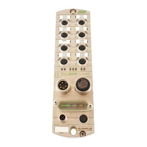
Murrelektronik Cube67 Series User manual

Handbuch
Manual
Manuel
Cube67

Murrelektronik GmbH Postfach 1165 71567 Oppenweiler Phone ++49 7191 47-0
Falkenstrasse 3 71570 Oppenweiler Telefax ++49 7191 47-130
Internet : http://www.murrelektronik.com
System Manual
For Modules Of The
Cube67 Series
- For use in combination with SW Version 2.xx -
User Manual Art. No. 56 970 Version 2.5


Cube67 System Manual
3 V 2.5
1ABOUT THIS MANUAL............................................................................................
Table of Contents
6
1.1 Chapter Overview...........................................................................................................................6
2SAFETY INSTRUCTIONS ........................................................................................7
2.1 Designated Use...............................................................................................................................7
2.2 Qualified Personnel........................................................................................................................8
2.3 Explanation of Symbols.................................................................................................................9
2.3.1 Use of Attention Signs..............................................................................................................9
2.3.2 Use of Danger Signs.................................................................................................................9
2.3.3 Use of Numbering in Illustrations............................................................................................9
2.3.4 Use of Handling Instructions ...................................................................................................9
2.3.5 Use of Footnotes.......................................................................................................................9
3THE CUBE67 SYSTEM ..........................................................................................10
3.1 System Components....................................................................................................................11
3.1.1 Product Designation...............................................................................................................11
3.1.2 Bus Node..................................................................................................................................12
3.1.3 I/O Modules..............................................................................................................................12
3.1.4 Compact Modules ...................................................................................................................12
3.1.5 Expander Modules ..................................................................................................................13
3.1.6 Supplementary Modules.........................................................................................................15
3.1.7 Function Modules....................................................................................................................15
3.1.8 NPN Modules...........................................................................................................................15
3.1.9 Cube20 Modules......................................................................................................................16
3.1.10 Customer-Specific Modules...................................................................................................16
3.1.11 Internal System Connection – Hybrid Line...........................................................................17
3.1.12 "External Power" cables.........................................................................................................18
3.1.13 Preterminated 7/8“ Power Cables..........................................................................................19
3.2 Internal System Connection........................................................................................................19
3.2.1 Current-Carrying Capacity .....................................................................................................20
3.2.2 Maximum Expansion...............................................................................................................20
3.2.3 Topology ..................................................................................................................................21
3.2.4 Bus Node Used As Power Distributor...................................................................................22
3.2.5 External Actuator Power Supply ...........................................................................................22
3.2.6 Terminal Resistance of the Internal System Connection....................................................23
3.3 Power Supply................................................................................................................................24
3.3.1 Configuration Notes................................................................................................................24
3.3.2 Recommended Power Supply Units MCSPower+................................................................25
3.4 Connecting Sensors and Actuators ...........................................................................................26
3.4.1 Sensor Power Supply .............................................................................................................26
3.4.2 Supply of External Modules (Art. No. 56 710 / 56 720) ........................................................27
3.4.3 Analog Setting Modules .........................................................................................................27
3.4.4 Actuators..................................................................................................................................27
3.4.5 DESINA Diagnostic Input .......................................................................................................28
3.4.5.1 Examples of Application of DESINA Diagnostic Function Pin 2........................................28
Cube67 System Manual
4 V 2.5
3.4.5.2 Connecting Sensors/Actuators with Diagnostic Output.....................................................28
3.4.5.3 Monitoring a Line for Line Breaks......................................................................................29
3.5 Electromagnetic Compatibility (EMC)........................................................................................ 29
3.5.1 Protection Against Electrostatic Discharge ........................................................................ 30
3.5.2 Grounding ............................................................................................................................... 31
3.5.3 Cable Routing ......................................................................................................................... 31
3.5.4 Voltage Drops ......................................................................................................................... 31
3.5.5 Separate Power Supplies....................................................................................................... 31
3.5.6 Inductive Load Interference Suppression............................................................................ 32
3.5.7 Limits and what can still be done... ...................................................................................... 32
4INDEX OF FIGURES.............................................................................................. 33
5INDEX OF TABLES................................................................................................ 34
LEGAL PROVISIONS................................................................................................... 35

Cube67 System Manual
5 V 2.5
Manual Revisions
Version
Chapter
Additions / Corrections
Date/Name
1.0
Issued by
24.04.03 / Hinze
1.1
Ch. 4
New modules
28.08.03 / Grofik
1.2
56740 new
04.12.03 / Grofik
1.3
Ch. 4.1.7 / 4.2.2 (10 m per branch)
15.04.04 / Hinze
1.31
Ch. 4.2 2
17.08.04 / Eberhard
1.4
Ch. 4.2 2
16.09.04 / Eberhard
1.5
New modules
05.11.04 / M.H./Gro
1.6
New module 56650
01.04.05 / M.H./Wie
1.7
New module 56662
15.09.05 / M.H./Wei
1.8
New modules
10.08.06 / M.H./Gro
1.9
1, 2.1
Info on Safety Category 3
08.10.07 / ri/vk
2.00
3.1.5
3.1.5
1
3.1.2
3.1.4
3.1.5
3.1.9
3.2.2
3.2.6
3.3.2
3.1.6
New module 5666100
New module 56641 C_Breit
Changes to CSC
Name Ethernet/IP
BN-DN V2 & BN-PNIO nodes
Module Table updated
MICO Table updated
SCREW PLUG in figure
Power supply units with ODVA
certification
Reference to Repeater Manual
20.05.08 / ber/ ri
27.05.08 / wol/ ri
24.09.08 / csc/ ri
2.1
New modules 56711, 56721, 56731,
56741, 56749
2.2
4.1.13
4.4.5.3
New table + reference to Catalog
and Online Shop
New EMC Directive 2004/108/EC
EN 954 => EN ISO 13849
Legal Provisions
Sturm/ri
2.3
3.1.5
New module 56642
18.01.2012 us/hi
2.4
3
Change of german text in headline 3
30.11.2012 us/csc
2.5
4.1.7
New module 56753
24.03.15 as/hi
Notes :

Cube67 System Manual
6 V 2.5
1 About This Manual
Please be sure to read this User Manual prior to starting up the equipment. The manual must be stored in
a visible location and be accessible to all users at all times.
User Manuals for Modules of the Cube67 Series :
Cube67 System Manual, Art. No. 56 970,
Cube67 Bus System Manual PROFIBUS Art. No. 56 980,
DeviceNet Art. No. 56 981,
CANopen Art. No. 56 982
Ethernet/IP Art. No. 56 983,
DeviceNet V2 Art. No. 56 984,
PROFINET Art. No. 56 985
Cube67 Technical Data Art. No 56 971.
Cube67 "Secure shutdown of malfunctioning secure modules“ Art. No. 56972
The text, illustrations, diagrams and examples presented in this manual serve solely for the purpose of
explanation, operation and use of Input/Output modules of the Cube67 series.
If you should have any further reaching questions regarding the installation and setup of the equipment
described in this manual, please do not hesitate to contact us. We are glad to assist you at any time.
Murrelektronik GmbH Postfach 1165 71567 Oppenweiler Phone ++49 7191 47-0
Falkenstrasse 3 71570 Oppenweiler Telefax ++49 7191 47-130
Internet : http://www.murrelektronik.com
Murrelektronik reserves the right to change technical specifications or contents of this manual at any time
without notice.
1.1 Chapter Overview
You must read the “Safety Information” section without fail before working with the products and the
system. This section contains information required for safe installation and handling.
The “Configuration Information“ section directs itself to system planners. It offers important information
and details relevant to successful configuration.
The Cube67 Technical Data manual contains comprehensive installation and technical information.
To set up the Cube67 field bus node, refer to the relevant user manuals of your field bus system.

Cube67 System Manual
7 V 2.5
2 Safety Instructions
2.1 Designated Use
The devices described in this manual are decentralized input/output modules intended for connection to a
field bus network.
The products described in this manual
•have been developed, manufactured, tested, and documented in compliance with the relevant
standards. The equipment poses no danger to operating personnel or material if configuration,
assembly and operation are performed in compliance with the stated handling and safety regulations.
•They meet the requirements contained in the standards and specifications listed in the datasheet.
Troublefree and safe function of this equipment is guaranteed only if the conditions for proper transport,
storage, installation and assembly are observed.
This manual contains no product application information as specified in EN ISO
13849. Refer to the following manual for this information: Cube67 "Secure shutdown
of malfunctioning secure modules“ Art. No. 56972
The designated operation of the equipment is guaranteed only when the housing is completely installed.
The power supply must comply with SELV or PELV. Power sources in accordance with EN 61558-2-6
(transformers) or EN 60950-1 (switched-mode power supply) meet these requirements.
Only qualified and suitably trained electrical tradesmen knowledgeable in the safety standards of
automation technology may perform configuration, installation, setup, maintenance, and testing of the
equipment.
Current safety and accident prevention laws valid for a specific application must be observed in the
configuration, installation, setup, maintenance and testing of the equipment.
Only cables and accessories are allowed which meet the requirements and regulations for safety,
electromagnetic compatibility and, where applicable, telecommunication transmission equipment and
specifications.
Information concerning the type of authorized cables and accessories can be obtained either from your
Murrelektronik distributor or are described in this manual.
CAUTION:
Good resistance to chemicals and oil. When using aggressive media, check the
material resistance based on the application.

Cube67 System Manual
8 V 2.5
2.2 Qualified Personnel
Requirements to be met by qualified personnel are based on qualification profiles described in ZVEI and
VDMA guidelines.
Weiterbildung in der Automatisierungstechnik (Further training in automation technology)
Herausgeber: ZVEI und VDMA (Publisher: ZVEI and VDMA)
Maschinenbau Verlag
Postfach 71 08 64
60498 Frankfurt
Only trained electricians familiar with the contents of this manual may be allowed to install and service the
components described here.
These are understood as being persons who,
•based on their trade qualification, experience and knowledge of relevant standards, are able to
assess the project requirements and to recognize possible hazards.
•based on extensive experience in comparable areas, possess the same level of knowledge as could
be expected of a trained electrician.
Only Murrelektronik technical personnel are allowed to undertake intervention in the hardware and
software of our equipment, unless the procedure is described in this manual.
CAUTION:
Unqualified intervention in the hardware and software of our equipment or disregard
of warnings and information provided in this manual may result in injury or serious
damage to humans and/or material.

Cube67 System Manual
9 V 2.5
2.3 Explanation of Symbols
2.3.1 Use of Attention Signs
Notes containing important information are specially marked. These are illustrated as follows :
Attention text........
2.3.2 Use of Danger Signs
Danger signs are additionally marked with a surrounding border.
CAUTION:
Disregard of safety measures may result in damage to equipment and other serious
consequences.
DANGER:
Noncompliance with the relevant safety measures poses a danger to the life
and limb of the user.
2.3.3 Use of Numbering in Illustrations
Illustrations are numbered with white numbers on a round black field.
Example : Text 1......
Text 2......
Text 3......
The explanatory text follows in tabular form under the same number, in direct context to the preceding
illustration.
2.3.4 Use of Handling Instructions
Handling instructions describe the sequence of steps during installation, setup, operation, and
maintenance that must be strictly observed.
The numbering (black numerals on a white field) is given in a sequential and ascending order.
Example : Instruction 1........
Instruction 2........
Instruction 3........
2.3.5 Use of Footnotes
Supplementary information is marked with superscript numerals (example: Text Text 1) Text Text). These
are explained in the form of footnotes under tables or text at the end of the page.

Cube67 System Manual
10 V 2.5
3 The Cube67 System
Fig. 3-1 : The Cube67 System
The Cube67 System is a tailor-made solution designed for decentralized applications in automation
systems. This innovative system offers new possibilities:
Cost-effective decentralization...
... distributed, modular, compact ,and robust design.
The I/O level is directly implemented in the machine, in the immediate proximity of sensors
and actuators, thus eliminating bulky and complex wiring.
Reduced dimensions ensure a compact and space-saving design of the machine.
Maximum flexibility...
... assured by multifunctional I/Os.
i.e. free parameterizability of the two signals per slot, whether input, diagnostic input or output.
"Fault detection instead of troubleshooting" – all-round diagnostic.
i.e. detailed information regarding the type and location of failures.
Channel-related diagnostics.
-Short-circuit in sensor power supply.
-DESINA Diagnostics.
-Actuator disable in case of short-circuit to 0 V or overload.
-Actuator warning in case of short-circuit to +24 V.
Graded voltage monitoring with diagnostic function.
Monitoring, cutoff and diagnosis of the Cube67 system connection.
Mount, plug in – done!

Cube67 System Manual
11 V 2.5
Configuration Notes
This chapter contains a brief description of the Cube67 System components and information relevant to
the electromechanical planning phase.
♦Product designation
♦Components
♦Topology
♦Permissible cable lengths
♦Current-carrying capacity
♦Power supply requirements
3.1 System Components
3.1.1 Product Designation
The designation of a Cube67 System component gives an indication of its function.
Example :
CUBE67
DIO16
C
8xM12
8 M12 slots
C
= compact module, E = expander module
16 digital I/O channels, freely configurable
A = Analog
D = Digital
I = Input
O =Output
Product Range

Cube67 System Manual
12 V 2.5
3.1.2 Bus Node
The task of the Cube67 System is to combine decentrally the signals of the I/O level and provide this
information over the field bus network (e.g. PROFIBUS). The central unit is the bus node, which
interconnects the Cube67 I/O modules and the field bus.
The bus node is powered via a 7/8“ power cable.
The bus node also has four connections for the internal system connection with connectivity for up to
four I/O modules. In this way, it is possible to connect up to 16 I/O modules to one bus node.
Table 3-1 : Bus nodes
Art. No.
Designation
56 501
Cube67 BN-DP
56 502
Cube67 BN-DN
56 507
Cube67 BN-DN V2
56 504
Cube67 BN-C
56 531
Cube67 BN-P Hybrid
56 505
Cube67 BN-E Ethernet/IP
56 506
Cube67 BN-PNIO
It is possible to connect up to 16 I/O modules to one bus node. Up to four I/O modules
can be attached to each terminal of the internal system connection.
3.1.3 I/O Modules
These modules are connected to the bus node via the internal system connection. I/O modules can be
either compact or expander units.
3.1.4 Compact Modules
A compact module has no extension interface for the internal system connection; consequently it is the
only, or the last module in a branch of the internal system connection.
The DIO 16 C 8xM12 also has a connection for an external actuator supply.
Table 3-2 : Compact modules
Art. No.
Designation
56 600
DIO 16 C 8xM12
56 610
DIO 8 C 4xM12
56 620
DIO 8 C 8xM8
56 602
DI 16 C 8xM12
56 612
DI 8 C 4xM12
56 622
DI 8 C 8xM8
56 640
DIO 16 C 8xM12 1,6 A
56 650
DO16 C Valve K3
56 700
AI4 C 4xM12 (U)

Cube67 System Manual
13 V 2.5
56 710
AO4 C 4xM12 (U)
56 720
AO4 C 4xM12 (I)
56 730
AI4 C 4xM12 (I)
56 740
AI4 C 4xM12 RTD
56 748
AI4 C 4xM12 TH
3.1.5 Expander Modules
Expander modules are fitted out with an extension interface for the internal system connection, i.e. the
latter can be routed to the following I/O modules. Up to four I/O modules can be used on a branch. In this
way, it is possible to connect up to 16 I/O modules to one bus node. An expander module can also be the
sole, or the last module in a branch. In this case, a terminal resistance must be installed on the extension
interface of the internal system connection (cf. chapter 0

Cube67 System Manual
14 V 2.5
Terminal Resistance of the Internal S).
Table 3-3 : Expander modules
Art. No.
Designation
56 600 2
DO32 E Valve 0.5 A Cable 2m
56 601
DIO16 E 8xM12
56 605
DO12 E 6xM12 K3
56 611
DIO8 E 4xM12
56 621
DIO8 E 8xM8
56 631
DIO8 E 4xM12 1A
56 603
DI16 E 8xM12
56 613
DI8 E 4xM12
56 623
DI8 E 8xM8
56 641
DIO16 DO16 E 16xM12
56 642
DIO32 E 16xM12
56 650
DO16 C Valve K3
56 651
DO16 E Valve
56 653
DO16 E MAC (0,5A)
56 655
DO8 E Valve
56 656
DO32 E Valve 0.5 A
56 657
DO32 E MAC
56 661
DIO8 E Cable
56 661 00
DIO8 E Cable 2 m
56 662
DIO16 E Cable 0.5 A
56 663
DIO8 E M16 0.5 A
56 671
DI16/DO16 E Cable 0.5 A
56 681
DIO8/DI8 E TB Box
56 691
DIO8/DI8 E TB Rail
56 701
AI4 E 4xM12 (U)
56 711
AO4 E 4xM12 (U)
56 721
AO4 E 4xM12 (I)
56 731
AI4 E 4xM12 (I)
56 741
AI4 E 4xM12 RTD
56 749
AI4 E 4xM12 TH

Cube67 System Manual
15 V 2.5
3.1.6 Supplementary Modules
Supplementary modules have neither I/O functions, nor connection to the internal system connection.
Diagnosis is only signaled by the LED indicators on the device. There is no diagnosis via the field bus.
Table 3-4 : Supplementary modules
Art. No.
Designation
56 955
PD 7/8”
56 960
R-P M12
For a functional description of Cube67 PD 7/8“ modules Art. No. 56 955, refer to chapter 3.2.5 External
Actuator Power Supply.
For a complete functional description of Cube67 R-P M12 Art. No. 56 960, refer to the PROFIBUS
Repeater Manual (Art. No. 56 960).
3.1.7 Function Modules
Function modules are modules which have special functions in addition to their regular I/O functionality.
Table 3-5 : Overview of function modules
Art. No.
Designation
56 750
CNT2 C 4xM12
56 760
DIO4 RS 485 E 3xM12
56 771
Logic E 4xM12
56753
ENC2 E 4xM12
3.1.8 NPN Modules
NPN modules are expansion modules with standard electronic functionality for NPN sensors.
Art. No.
Designation
56 606
DI16 E 8xM12 NPN
56 616
DI8 E 4xM12 NPN
56 626
DI8 E 8xM8 NPN

Cube67 System Manual
16 V 2.5
3.1.9 Cube20 Modules
For information on Cube20 module, refer to the Cube20 manuals.
3.1.10 Customer-Specific Modules
Customer-specific modules are modules which are based on a standard module and which are adapted
to customer-specific solutions (e.g. different plug, cable length).
Table 3-6 : Overview of customer-specific modules
Art. No.
Designation
56 665 00
DIO8 E Cable M12 ID
56 601 50
DIO16 E 8xM12 VA
56 601 51
DIO16 E 8xM12 VA
56 611 50
DIO8 E 4xM12 VA
56 621 50
DIO8 E 8xM8 VA
56626 50
DI8 E 8xM8 NPN VA
56 603 50
DI16 E 8xM12 VA
56 701 50
AI4 E 4xM12 (U) VA
56 720 50
AO4 C 4xM12 (I) VA
56 730 50
AI4 C 4xM12 (I) VA
56 740 50
AI4 C 4xM12 RTD VA
56 748 50
AI4 C 4xM12 TH VA
56 651 00
56 600 1
DO16 E Valve CPV
DO16 E Valve CPV 1.4 m
56 651 01
DO16 E Valve V
56 651 10
DO16 E Valve V20/22
56 651 11
DO16 E Valve VM10
56 651 12
DO16 E Valve V20/22 B
56 651 13
DO16 E Valve SMC
56 651 14
DO16 E Valve SMC M27
56 651 15
DO16 E Valve V20/22 C
56 651 16
DO16 E Valve MAC
56 651 51
DO16 E Valve CPV VA
56 651 52
DO16 E Valve SMC VA
56 681 00
DIO8/DI8 E TB Box PK
56 655 00
DO8 E Valve CPV
56 655 01
DO8 E Valve CPV(9)
56 656 00
DO24 E Valve VM10

Cube67 System Manual
17 V 2.5
Art. No.
Designation
56 656 01
DO24 E Valve MPA
56 656 02
DO32 E Valve HF03
56 656 03
DO32 E Valve VM10
56 656 04
DO23 E Valve SMC
56 656 05
DO22 E Valve CPA
56 656 06
DO24 E Valve HF04
56 656 07
DO24 E Valve SMC M27
56 656 09
DO32 E Valve MAC
56 656 10
DO32 E Valve Vesta
56 656 11
DO22 E Valve Vesta
56 665 00
DIO8 E Cable M12 ID
56 600 0
DIO8 E Cable M12 ID 1,2m
3.1.11 Internal System Connection – Hybrid Line
The green system line is a shielded hybrid line for
- communication between bus node and I/O modules.
- transfer of sensor supply.1
- transfer of actuator power supply.
Use only our preterminated lines for the internal system connection.
Table 3-7 : Internal system connections
Length
Art. No.
straight-straight
90°-90°
0.3 m
7000-46041-8020030
7000-46061-8020030
0.6 m
7000-46041-8020060
7000-46061-8020060
1.0 m
7000-46041-8020100
7000-46061-8020100
1.5 m
7000-46041-8020150
7000-46061-8020150
2.0 m
7000-46041-8020200
7000-46061-8020200
2.5 m
7000-46041-8020250
7000-46061-8020250
3.0 m
7000-46041-8020300
7000-46061-8020300
3.5 m
7000-46041-8020350
7000-46061-8020350
4.0 m
7000-46041-8020400
7000-46061-8020400
4.5 m
7000-46041-8020450
7000-46061-8020450
5.0 m
7000-46041-8020500
7000-46061-8020500
5.5 m
7000-46041-8020550
7000-46061-8020550
6.0 m
7000-46041-8020600
7000-46061-8020600
6.5 m
7000-46041-8020650
7000-46061-8020650
7.0 m
7000-46041-8020700
7000-46061-8020700
7.5 m
7000-46041-8020750
7000-46061-8020750
1The supply voltage of Cube67 I/O modules is drawn from the sensor power supply.

Cube67 System Manual
18 V 2.5
Length
Art. No.
straight-straight
90°-90°
8.0 m
7000-46041-8020800
7000-46061-8020800
8.5 m
7000-46041-8020850
7000-46061-8020850
9.0 m
7000-46041-8020900
7000-46061-8020900
9.5 m
7000-46041-8020950
7000-46061-8020950
10.0 m
7000-46041-8021000
7000-46061-8021000
Table 3-8 : Contact arrangement of the system connection
Arrangement
Contacts
Meaning
Male
1
Actuator power supply
2
Sensor power supply / internal module power supply
3
Ground
4
Internal system connection
5
Internal system connection
6
Ground
Female
1
Actuator power supply
2
Sensor power supply / internal module power supply
3
Ground
4
Internal system connection
5
Internal system connection
6
Ground
3.1.12 "External Power" cables
The odd-numbered M12 sockets (1,3,5,7) of Cube67 DIO16 C 8xM12 compact modules require an
external actuator power supply, which is provided via an "External Power" cable.
Table 3-9 : External power cables
Length
Art. No.
straight-straight
90°-90°
0.3 m
7000-46001-4140030
7000-46021-4140030
0.6 m
7000-46001-4140060
7000-46021-4140060
1.0 m
7000-46001-4140100
7000-46021-4140100
1.5 m
7000-46001-4140150
7000-46021-4140150
2.0 m
7000-46001-4140200
7000-46021-4140200
2.5 m
7000-46001-4140250
7000-46021-4140250
3.0 m
7000-46001-4140300
7000-46021-4140300
3.5 m
7000-46001-4140350
7000-46021-4140350
4.0 m
7000-46001-4140400
7000-46021-4140400
4.5 m
7000-46001-4140450
7000-46021-4140450
5.0 m
7000-46001-4140500
7000-46021-4140500

Cube67 System Manual
19 V 2.5
3.1.13 Preterminated 7/8“ Power Cables
The Cube67 System is supplied with voltage via a 7/8" connector. The voltage supply for the sensors and
actuators can be fed in separately. The ground of both supply voltages is connected internally. The
operating voltage of the Cube67 components is drawn from the sensor power supply.
Table 3-10: 7/8“ power cable
Length
straight - straight
angled - angled
0.3 m
0.6 m
1.0 m to 10.0 m
in steps of 0.5 m
For more information on 7/8“ power cables, please refer to our catalog or our online
shop at:
onlineshop.murrelektronik.com
3.2 Internal System Connection
Use only our preterminated lines for the internal system connection.
CAUTION:
Inverting Cube67 I/O modules in a system may result in injury or serious damage to
humans and/or material.
When comparing planned and actual configuration, the Cube67 system is basically
unable to distinguish between identical or replaceable modules. Therefore, it is
important to label Cube67 system cables and Cube67 I/O modules clearly.
This manual suits for next models
14
Table of contents
Other Murrelektronik Control Unit manuals

Murrelektronik
Murrelektronik IMPACT67-P User manual

Murrelektronik
Murrelektronik CUBE20S User manual

Murrelektronik
Murrelektronik IMPACT67 Series User manual

Murrelektronik
Murrelektronik Data Panel xtreme DB DP-34044-2 User manual

Murrelektronik
Murrelektronik MVK-MPNIO Series User manual

Murrelektronik
Murrelektronik Data Panel xtreme DB DP-34044-1 User manual

Murrelektronik
Murrelektronik MVK-MP User manual