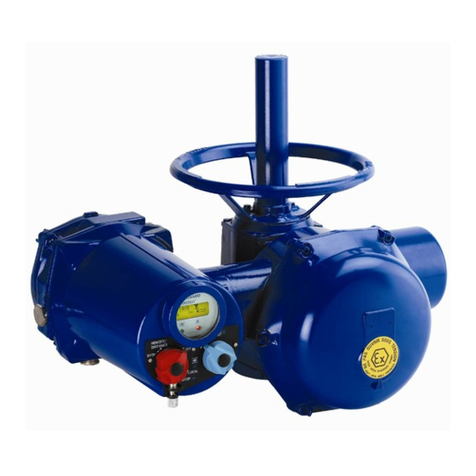
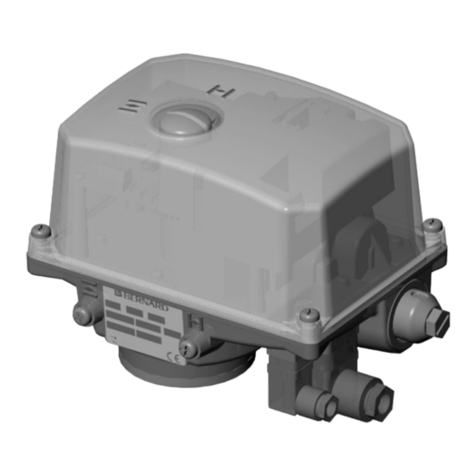
Bernard FQ Series User manual

InstructIons de mIse en servIce
GAmme Fq
InstructIons For stArt-up
rAnGe Fq
BetrIeBsAnleItunG
stellAntrIeBe Fq
NR 1043 REV. C
Fq

2 3
1 PRéCAUTIONS D’UTILISATION
Attention : L’appareil renfermant un ressort sous tension ne peut être démonté qu’avec un outilla-
ge
approprié. Seul l’accès au boîtier de contrôle ne nécessite pas d’équipement particulier (voir cro-
quis).
2 MISE EN SERVICE :COMMANDE éLECTRIQUE
•Vérierlanatureetlatensionducourant.
•Ce servomoteur à rappel par ressort est, lorsqu’il est hors tension, en appui sur une des
butées quart de tour. Un démarrage du moteur dans
le mauvais sens de rotation risque d’endommager le
matériel.
Ilestdoncimpératifavantd’embrayerlemoteur,devérierson
sens de rotation.
Pour ce faire :
•Ne pas brancher l’électro-frein (voir schéma de
câblage).
•Basculer le levier de commande manuelle lorsqu’il
existe, vers le servomoteur.
•Alimenterlemoteuretvériersonsensderotation
(flèche indicatrice sur le moteur).
•Brancherlesnsdecourseetvérierleurfonction-
nement par action manuelle sur les microcontacts.
•Aprèscesvérications,nepasoublierderebrancherl’électrofrein.
3 RèGLAGE DES BUTEES MéCANIQUES (QUART DE TOUR)
Hors tension, le servomoteur est en appui sur une des butées mécaniques. Pour modier cette
position, visser ou dévisser la butée correspondante, accessible sur le côté de l’appareil.
4 RèGLAGE DES FINS DE COURSE
Les cames actionnant les microswitches sont logées dans un bloc entraîné par l’arbre de sortie.
Mode opératoire :
1 - Placer un petit tournevis dans la fente correspondant à la came à déplacer.
2 - Appuyer légèrement pour libérer la came.
3 - Tourner indifféremment dans un sens ou l’autre pour amener la came dans la position
recherchée.
4 - Relâcher et s’assurer que la tête est remontée en position d’origine, ce qui verrouille
automatiquement la came.
Attention :Lendecoursedoitcouperl’alimentationmoteuravantd’arriversurlabutéemécani-
que.
5 RèGLAGE DE L’INDICATEUR DE POSITION
Le disque indicateur de position est vissé sur un axe. Desserrer la vis et positionner la flèche en face
du repère correspondant du capot puis revisser.
6 MISE EN SERVICE :COMMANDE MANUELLE
En cas de manque de courant, une utilisation du servomoteur est possible grâce au volant de
commande manuelle (uniquement sur les modèles FQR).
Mode opératoire :
•Déverrouiller si nécessaire, le levier d’embrayage
(sur le côté de l’appareil) en enlevant le cadenas (en
option).
•Basculerlelevierversl’extérieur.
•Tournerlevolantpourmanoeuvrerlavanne.
Attention : Lorsque le levier est en position commande
manuelle, la fonction retour en position de sécurité
n’est plus assurée.
Pour ramener le servomoteur en position de sécurité, rabattre
le levier d’embrayage vers le boîtier. L’énergie emmagasinée
dans le ressort permet le retour automatique en position de
sécurité.

4 5
1 CAUTIONS BEFORE COMMISSIONING
Warning: This actuator includs one compressed spring which can be dismounting only with special
tools. The control box remains accessible without having to use special tools.
2 ELECTRICAL CONNECTIONS AND OPERATION
•Checkthepowersupplytype.
•WhenthepowersupplyisOFF,theactuatorisononeofitsmechanicalstops.
An incorrect electric motor rotation could damage the actuator.
Thenchecktheelectricrotationdirection.
•Donotenergizethebrake.
•Pull down the declutch lever (when the actuator has
an handwheel).
•Put the power on the motor and check the right
rotation direction (arrow on the motor).
•Connectthetravellimitswitchesandcheckbyswit-
ching them if they are functioning correctly.
•Afterabovecontrols,donotforgettoplug(energize)
thebrake.
3 MECHANICAL STOPS SETTING
WhenthepowersupplyisOFF,theactuatorisononeofitsmechanicalstops.Tomodifythisposition,
screw or unscrew the corresponding mechanical stop then lock the nut on the screw to keep
the position. The mechanical stops and nuts are located outside the actuator housing.
4 TRAVEL LIMIT SWITCHES SETTING
Thecamsactioningthemicroswitchesarelocatedinablockwhichisdrivenbythemainshaft.
1 - Put a screwdriver in the corresponding slot of cam to set.
2 - Push slightly to engage and turn left or right according to the required cam position.
3 - Remove the screwdriver and ensure that the button has come back to its original
position,thuslockingthecaminthechosenposition.
4 - Makesurethattheelectricmotorhasstoppedbythetravellimitswitchandnotbythe
mechanical stop.
Caution: Always the travel limit switches have to cut off the motor power supply before to reach
the mechanical stops.
5 POSITION INDICATOR SETTING
Thedialindicatorisxedonashaft.Unlockthescrewandpositionthearrowinfrontofthecorres-
pondingpositionshownonthecoverthenlockthescrew.
6 MANUAL OPERATION
In case of power failure the actuator can be used through the handwheel (only on types FQR).
Proceed as follows:
•Unlockifnecessary,theclutchinglever(ontheside
oftheactuator)byremovingthepadlock(optionalequipment).
•Pulldownthelevertoengagethehandwheel.
•Turnthehandwheeltodrivethevalve.
Warning: Whenthe leveris in amanualposition, no fail-safe
action is available.
Tobringtheactuatorbackintoitssafeposition,placethelever
in its original position. The remaining energy of the spring will
allowanautomaticcome-backinthesafeposition.

6 7
1 HINWEISE BEACHTEN
Wichtig : der Federrückstellungsantrieb beinhaltet eine komprimierte Feder, die nur mit Spezia-
lwerkzeugentferntwerdenkann.DerSchaltraumkannohneSpezialwerkzeuggefahrlos
geöffnet werden (siehe Abbildung).
2 ELEKTRISCHER ANSCHLUSS
•PrüfenSiedieSpannungsversorgung.
•Wenn keine Spannung angeschlossen ist, ist der
Antrieb durch die Federkraft auf die mechanische
Begrenzung gefahren. Falsche Drehrichtung des
Antriebskanndiesenzerstören.
•PrüfenSiedeshalbdieDrehrichtung.
•SchließenSiedenMagnetennichtan
•Schließen Sie den Motor an und prüfen Sie die
Drehrichtung (siehe Pfeil auf dem Motor).
•Schließen Sie die Wegbegrenzungsschalter an und
prüfenSieIhreFunktion.
•SchließenSieerstdanndenMagnetenan,wennalle
vorherigenPunkteüberprüftsind.
3 MECHANISCHE ENDANSCHLÄGE
WennkeineSpannungangeschlossenist,istderAntriebdurchdieFederkraftaufdiemechanische
Begrenzunggefahren.Um diePositionzu verändern, schraubenSie die entsprechendeSchraube
entweder weiter in den Antrieb oder dementsprechend heraus. Kontern Sie dann die mechanischen
EndanschlägeindergewünschtenPosition.
Schrauben und Kontermuttern der mechanischen Endanschläge sind außerhalb des Antriebs
angebracht
4 EINSTELLEN DER WEGBEGRENZUNGSSCHALTER
Die Nocken, die die Wegbegrenzungsschalter auslösen, sind in einem Block zusammengefaßt,
der von der Antriebswelle bewegt wird.
EinstellenderNocken:
1-SteckenSiedenSchraubendreherindenSchlitzderNocke,dieSieverstellenwollen.
2-DrückenSiedenDruckknopfzumEntriegelnderNockeein.
3 - ImeingedrücktenZustand wirddieNockedannnachrechtsoderlinksverdrehtund
dieNockeentsprechendverstellt.
4 - Der Schraubendreher wird nun herausgezogen; dabei geht der Druckknopf in die
AusganslagezurückunddieNockewirdautomatischverriegelt.
5 EINSTELLEN DER MECHANISCHEN STELLUNGSANZEIGE
DieScheibe der mechanischen StellungsanzeigeistaufeinerWelleaufgeschraubt.LösenSiedie
SchraubeundziehenSiedieAnzeigenscheibevomSchaftabundsteckenSiedieseindierichtige
Position,dieaufdemGehäusedeckelablesbarist,zurück.SchraubenSiedanndieAnzeigenscheibe
wiederfestundschließenSiedenDeckel.
6 HAND-NOT-BETÄTIGUNG
ImFalleeinesStromausfallskannderAntriebmittelsHandrad
notbetätigtwerden(nurbeiFQR).
Verfahren Sie wie folgt :
•LegenSiedenKupplungshebelzumEinkuppelnum.
•DrehenSiedasHandradzurBetätigungderArma-
tur.
Warnung : WennderHebelin«Handbetätigung»steht,isteine
Federrückstellungnichtmöglich.

AUSTRIA
IPU ING PAUL UNGER
WIEN
Tel. : +43 1 602 41 49
BELGIUM
BERNARD CONTROLS BENELUX
Info.benelux@bernardcontrols.com
BRUXELLES
Tel. : +32 (0)2 343 41 22
BRAZIL
JCN
[email protected]om.br
SAO PAULO
Tel. : +55 11 39 02 26 00
CHINA
BERNARD CONTROLS CHINA
bcc.info@bernardcontrols.com
BEIJING
Tél. : +86 (0) 10 6789 2861
CZECH REPUBLIC
FLUIDTECHNIK BOHEMIA s.r.o.
brno@fluidbohemia.cz
BRNO
Tel. : +420 548 213 233-5
DENMARK
ARMATEC A/S
GLOSTRUP
www.armatec.dk
Tel. : +45 46 96 00 00
EGYPT
ATEB
gm@atebco.com
ALEXANDRIA
Tel. : +203 582 76 47
FINLAND
TALLBERG TECH OY AB
pekka.tontti@tallberg.fi
ESPOO
www.soffco.fi
Tel. : +358 0 207 420 740
GERMANY
BERNARD CONTROLS DEUFRA
bcd.mail@bernardcontrols.com
TROISDORF
Tel. : +49 22 41 98 340
GREECE
PI&MS Entreprises Ltd
HALANDRI
Tel. : +30 210 608 61 52
HUNGARY
APAGYI TRADEIMPEX KFT
BUDAPEST
Tel. : +36 1 223 1958
IRAN
ASIA INSTRUMENTS Co. Ltd.
TEHRAN
www.asiainstrumentsltd.com
Tel. : +98 21 8850 3065
ITALY
BERNARD CONTROLS ITALIA
info.it@bernardcontrols.com
RHO /MILANO
Tel. : +39 02 931 85 233
MALAYSIA
ACTUATION & CONTROLS
ENGINEER
JOHOR BAHRU
Tel.: +60 7 23 50 277 / 23 50 281
MIDDLE-EAST
BERNARD CONTROLS
MIDDLE-EAST
bernact@emirates.net.ae
DUBAI - U.A.E.
Tel. : +971 4 39 80 726
MOROCCO
AQUATEL sarl
CASABLANCA
Tel. : +212 22 66 55 71
NETHERLANDS
BERNARD CONTROLS BENELUX NV
hans.nobels@bernardcontrols.com
AN ZWAAG
Tel. : +31 (0)229-298083
NEW ZEALAND
MRCTRANSMARK NZ LTD
bill.sunley@mrctransmark.com
AUCKLAND
Tel. : +64 9 276 4149
NORWAY
KSB LINDFLATEN AS
firmapost@lindflaten.no
LYSAKER
Tel. : +476 71 29 900
POLAND
MARCO
matzank[email protected]
WARSAW
Tel. : +48 22 864 55 43
PORTUGAL
PINHOL, GOMES & GOMES LDA.
[email protected]om.pt
CARNAXIDE
Tel. : +351 21 425 68 50
RUSSIA
BERNARD CONTROLS RUSSIA
bernard@amotek.net
c/o AMOTEK - MOSCOW
Mob. : +7 917 562 8591
Tel./Fax : +7 495 343 43 80
RUSSIA
A.E.T. (agent)
ST PETERSBURG
Tel./Fax : +7 812 320 55 97
Mob. : +7 812 956 35 14
SINGAPORE
ACTUATION & CONTROLS ENG.
(ASIA)
[email protected]om.sg
SINGAPORE
Tel. : +65 65 654 227
SPAIN
BERNARD CONTROLS SPAIN
bernardserv[email protected]
MADRID
Tel. : +34 91 30 41 139
SOUTH AFRICA
A-Q-RATE AUTOMATION CC
BERTSHAM
Tel. : +27 11 432 58 31
SOUTH KOREA
RENTEC CO Ltd (Water market)
totor[email protected]om
GYEONGGI-DO
Tel. : +82 31 399 73 23
SOUTH KOREA
YOO SHIN E&I Co. Ltd
(Oil & Gas market)
SEOUL
Tel. : +82 2 406 62 78
SWITZERLAND
MATOKEM AG
info@matokem.ag
ALLSCHWIL
www.matokem.ch
Tel. : +41 61 483 15 40
THAILAND
BERNARD CONTROLS
SOUTH-EAST ASIA
j.chounramany@bernardcontrols.com
BANGKOK
Tel. : +66 2 640 82 64
TURKEY
OTKONSAS
sales@otkonsas.com
ISTANBUL
Tel. : +90 216 326 39 39
UNITED ARABS EMIRATES
EMIRATES HOLDINGS
emhold@emirates.net.ae
ABU DHABI
Tel. : +97 12 644 73 73
UNITED-KINGDOM
ZOEDALE Plc
BEDFORD
Tel. : +44 12 34 83 28 2
USA/CANADA/MEXICO
BERNARD CONTROLS Inc
bsales@bernardcontrols.com
HOUSTON - TEXAS
Tél. : +1 281 578 66 66
BERNARDCONTROLS
4 rue d’Arsonval - BP 70091 - 95505 Gonesse Cedex - France
Tel: +33.1. 34.07.71.00 - Fax: +33.1.34.07.71.01
E-mail: mail@bernardcontrols.com
Internet: http://www.bernardcontrols.com
Table of contents
Languages:
Other Bernard Controllers manuals
Popular Controllers manuals by other brands
Meanwell
Meanwell DLC-02 installation manual

Clear One
Clear One COLLABORATE Live Conference Controller user guide
Aqua Medic
Aqua Medic T Controller HC Operation manual
ICON
ICON ProCon C700 Series operating manual

Kieback&Peter
Kieback&Peter MD15-FTL-315 user manual

Light Symphony
Light Symphony LS30505SCC instructions
