Operation Notes Please read this manual carefully before using to ensure correct usage and
maintenance worker safety.
Do not wear loose clothes, ties, rings, or bracelets and ensure to wear the hairnet to
prevent them from getting caught in the machine by accident and cause injury or
danger during operation.
To stop using the robot, please turn off the power and isolate the energy source until
the robot stops completely before leaving.
Make sure that there is no one inside the fences before operating the robot.
Do not chat with each other when operating the robot. Otherwise, it may cause
dangers such as robot collisions or personal injury.
When teaching the robot for the first time, do not stand within the robot's motion
range to avoid danger due to being unfamiliar with the operation.
Use slow speed operation when operating the robot manually for the first time,
otherwise it may cause damage to the robot or dangers such as personal injury.
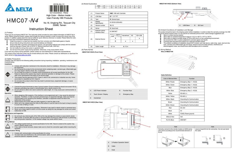
To remove the teach pendant cable on the controller, please do so when it is
completely powered off, otherwise it may cause damage to the teach pendant.
Adjust the parameter settings before operating the robot. If not adjusted correctly,
the robot may be out of control or malfunctioning. Make sure that the emergency
stop device can be activated at any time before operating the robot. When powering
on, make sure that the robot remains stationary and does not move due to inertia or
other reasons.
Do not touch any rotating parts when the robot is operating, otherwise it may cause
personal injury.
Do not change any parts on the handheld teach pendant, including the emergency
stop and the enable switch. Doing so may lower the safety performance and level or
even lose safety protection.
Do not short-circuit the safety protection signal on the controller in any way. We shall
not be liable for any occupational accident.
When operating the robot, do not allow anyone to approach or stand within the
working range of the robot, otherwise it may cause personal injury.
Do not unplug any cables on the controller while the robot is operating, otherwise it
may cause damage to the controller.
To prevent accidents, please separate the jigs of the robot before the first
commissioning. If an operation error occurs after the servo motor and the robot are
running, it may cause damage to the robot as well as personal injury. It is strongly
recommended to test if the robot is working normally without any load before
connecting loads to avoid unnecessary hazards.
Do not touch the control box during operation, otherwise it may cause burns or
electric shocks due to high temperature.
Do not touch the controller and the inside of the robot, otherwise it may cause
electric shocks. Do not remove the handheld HMI when the power is on,
otherwise it may cause electric shocks and damage to the handheld HMI. Do
not touch the wiring terminals within 30 minutes after turning off the power as
residual voltage may cause electric shocks. Do not modify the wiring while the
power is on, otherwise it may cause electric shocks or personal injuries. The
installation, wiring, repair, and maintenance of this robot must be performed
by trained and qualified electricians only.
