manuals.online logo
Brands
  1. Home
  2. •
  3. Brands
  4. •
  5. Securam
  6. •
  7. Lock
  8. •
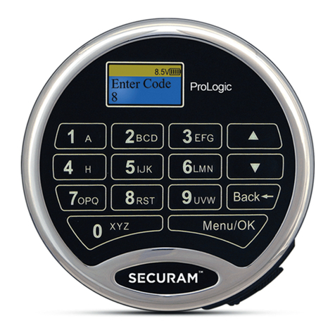
  9. Securam ProLogic L02-C User manual

Securam ProLogic L02-C User manual

ProLogic L02-C Operation Instructions
1
ProLogic L02-C Operation Instructions
Document No: EC-0601A-L02-C-160617
Version No: V1.01
1.0 System Installation
1.1 System Components
1.2 Pairing the EntryPad with the Lock(s)
1.3 Lock and EntryPad Installation
1.4 Installing Battery
1.5 Test Lock Operation
2.0 Lock Operation
2.1 Opening the Lock
2.2 Opening the Lock in Time Delay
2.3 Opening the Lock in Dual Control
2.4Opening the Lock with a Multi-Lock System
3.0 Code Management
3.1 Code Length Options
3.1.1 PW L –6 / Users 10
3.1.2 PW L –8 / Users 30
3.1.3 PW L –6 / Users 30
3.2 Enrolling New users
3.3 Change Code
3.4 Delete One User
3.5 Delete All Users
3.6 Disable/Enable User
3.7 Obfuscate Code Entry
4.0 System Identification
4.1 System Info
5.0 Time Delay
5.1 Set/Cancel Time Delay
5.2 Setting Time Delay Override Users
6.0 Single or Dual Control
6.1 Enable Dual Mode
6.2 Dual Mode Group ID
7.0 Manager Mode
7.1 Enable Manager Mode
7.2 Disable Manager Mode
8.0 Door Management
8.1 Configuring a Multi-lock system
8.2 Set Number of Locks
8.3 Authorize Locks
8.4 Enable Sequence
9.0 Data Management
9.1 Encryption Key Set
10.0 Recovering the System –Reset to Default
10.1 Recovery Code Set
10.2 Recover System
10.4 Mechanical Reset
11.0 System Testing
11.1 Cycle Testing
12.0 Menus
12.1 The ProLogic L02-C Menus
IMPORTANT: It is imperative that all programming be completed with the safe
door in its open position, such that the programmer can gain access to the lock
body in the event of an incorrect programming.
ProLogic L02-C Operation Instructions
2
1.0 System Installation
1.1 System Components
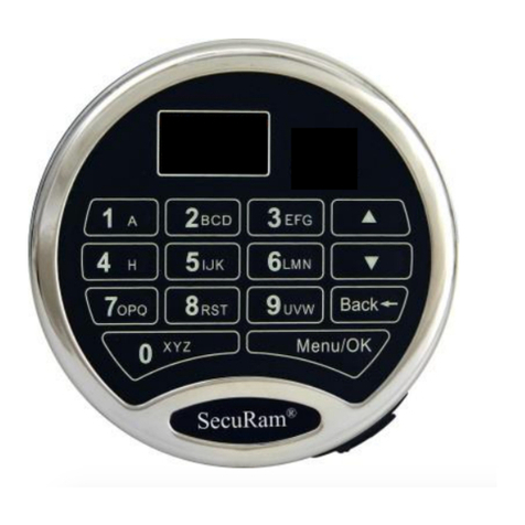
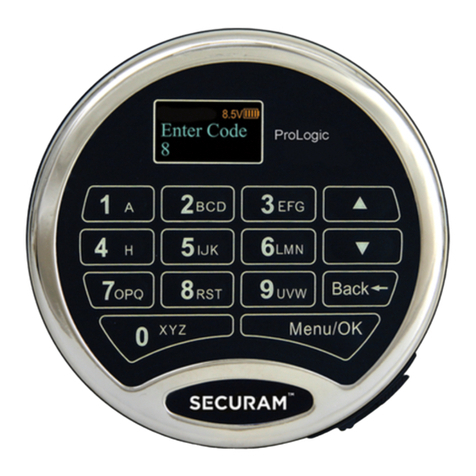
The system consists of (1) EntryPad –Part # EC-0601A-L02-C plus (1) or more Lock bodies as follows:
SwingBolt –Part # EL-0601
SwingBolt with Status Sensor –Part # EL-0601-S
DeadBolt –Part # EL-0701
SpringBolt –Part #EL-0801
Note: The ProLogic L02-C can control up to 4 locks when used in conjunction with the Expansion Box –
Part # CB11-1T4. (If setting up a multi-lock system, please refer to Section 10.2 –Multi-Lock Systems)
1.2 Pairing the EntryPad and the Lock
SecuRam safe lock systems can operate in two different modes depending upon the type of EntryPad
being used with the lock body. The ProLogic L02-C is a digital lock system and therefore the lock must
also be programmed in digital mode. Both modes follow the same steps to reset / set which is done by
following the steps detailed below:
Step 1: Ensure the battery is connected to the Entry Pad.
Step 2: Ensure the lock cable is disconnected from the lock body.
Step 3: Locate the Reset Hole on the back of the lock (under the QC sticker).
Step 4: Using a paper clip depress the reset button, inside the reset hole, 3 times to dissipate
any latent energy in the lock.
Step 5: Now depress the reset button and hold.
Step 6: While continuing to depress the reset button, connect the lock cable to the lock body.
Step 7: Continue to hold down the reset button for 5 seconds and then release.
Step 8: Verify that the pairing has been completed, by opening the lock with the default code
111111.
Step 9: Press any button on the EntryPad to initiate a lock communication test. The EntryPad
will display the following information:
ProLogic L02-C Operation Instructions
3
Followed by:
Enter a valid code to test the lock.
The Default codes are as follows:
Super Code (ID00) is 111111
Manager Code (ID01) is 123456
Upon entry of a valid code, the lock will open. If the lock does not open and the LCD screen
displays the message “Fail to Link with Lock”, repeat the reset procedure. Be sure to hold down
the reset button through steps 5-7.
If you have difficulty resetting the lock, please call SecuRam Tech Support at (805) 988-8088 or email
info@securamsys.com.
1.3 Lock and EntryPad Installation
Included within your installation kit are (2) shoulder bolts and (3) lock mounting bolts.
Install the shoulder bolts on the safe door in the pre-drilled holes above and below the spindle
hole.
Now insert the lock cable (attached to the EntryPad) through the spindle hole.
On the backside of the safe door, you will see the lock mounting plate and the predrilled lock
mounting holes.
Connect the lock cable to the lock body and position the lock body appropriately on the lock
mounting plate.
Ensure that the lock cable is positioned so that it lies in the channel on the back of the lock. This
channel is provided to protect the lock cable from damage or crimping during installation.
Using the provided lock bolts, secure the lock body to the mounting plate.
Note: it is very important to ensure that there is an adequate gap between the lock bolt and the
boltwork. This gap must be 0.125”.
1.4.1 Installing the Battery –Standard Battery Compartment (located on the back of the EntryPad)
Connect the battery terminal clip to the 9V battery. (Duracell or Energizer brands are
recommended).
Position the battery so that the terminals are in the downward position and push the battery
into the battery compartment. See Fig. 1.
Carefully tuck the excess lock cable into the cavity on the back of the EntryPad and install the
EntryPad on the shoulder bolts. See Fig. 2.
ProLogic L02-C Operation Instructions
4
Be careful not to crimp or damage the lock cable upon EntryPad installation.
1.4.2 Installing the Battery –SureLock Battery Compartment (removable battery compartment)
Locate the SureLock Battery Compartment at the 5 o’clock position of the EntryPad. See Fig. 3.
Release the latch of the battery compartment, by pulling lever downward. See Fig 4.
Pull out the battery compartment from the bottom of the EntryPad. See Fig 5.
Install a new 9V alkaline battery (Duracell or Energizer brands are recommended) into the
compartment. The battery compartment will only receive the battery when the positive and
negative terminals are oriented correctly. See Fig. 6
Put the battery compartment back into the EntryPad. Push the latch of the battery
compartment up until it snaps closed. See Fig. 3
1.5 Testing the Lock Operation
The ProLogic L02-C comes with two factory default codes:
•Super Code (ID00) is 111111
•Manager Code (ID01) is 123456
Enter one of the valid codes to verify that the communication between the lock and EntryPad. The lock
will open.
ProLogic L02-C Operation Instructions
5
2.0 Lock Operation
Upon initial power up, the LCD screen starts a communications test as shown below:
Including Model Number
Software Version Number
No. of Users/ No. Users Programmed
Lock ID#/Host ID#
Model Name
After this initial power up it will also check to ensure that the system is communicating correctly. The
display will read “Link with Lock OK”.
If the Display reads: “Fail to Link with Lock” proceed to Section 1.2 entitled “Pairing the EntryPad and
the Lock”
2.1 Opening the Lock
The safe lock system has two default codes installed as follows:
•Super Code (ID00) 1-1-1-1-1-1
•Manager Code (ID01) 1-2-3-4-5-6
Step 1: Enter a valid code –for example ID00.
The display will read “ID00 Verified”.
And the Lock will open.
The display will read:
The lock will relock after 6 seconds.
Note: Time to relock is hard coded and cannot be changed.
2.2 Opening Lock with Time Delay Programmed
When Time Delay has been programmed, the user must enter a valid code.
Note: Users are defined as ID03- ID30
ID00
ProLogic L02-C Operation Instructions
6
Wait through the preprogrammed time delay period, then enter the code again to open the lock safe, as
follows:
Step1: Enter a valid code
Note: ID00, ID01 and ID02 are Administrator users and will bypass Time Delay.
Step 2: Display will read “Time Delay Start”
Step 3: Display will flash on every 15 seconds, counting up until it reaches the preprogrammed
time delay value.
Note: Administrators can override Time Delay to open lock anytime.
Step 4: When Time Delay expires, the EntryPad will beep twice then display: “Time Window
XX:00”, indicating the length of time the User has to enter a valid user code to gain entry.
The Counter will count down until the Time Window has expired. A user code is used to open
the lock.
Step 5: Enter a valid Code to open the lock.
2.3 Opening the Lock in Dual Control
The ProLogic L02-C can be programmed so that two User codes are required to open the lock. This
function is called “Enable Dual Mode”, See 8.1
To Open a Lock under Dual Control:
Step 1: Enter User code
The display will read “IDXX Verified”.
For example, ID03 will display “ID03 Verified”.
The display will then read:
“Enter 2nd User Code”
ProLogic L02-C Operation Instructions
7
For example, using ID04 for 2nd code will read “ID04 Verified”.
The lock will open and relock in 6 seconds.
2.4 Opening the Lock with a Multi-Lock System
The ProLogic L02-C can operate up to 4 locks.
To Open a Lock with a Multi-Lock System:
Step 1: Enter a valid code
The display will read “IDXX Verified”.
Step 2: The system will now prompt you to enter the number of the Lock to open
3.0 Code Management
The ProLogic L02-C comes with two default codes:
•Super Code (ID00) is 111111
•Manager Code (ID01) is 123456
It is strongly recommended that both these default codes are changed before the lock system is put into
service.
The ProLogic L02-C has the capability to add up to 29 codes, in addition to the default codes.
ID02 is a Manager Code and therefore has management functionality (the same as ID01).
ID03-30 are User Codes.
3.1 Code Length Options
The ProLogic L02-C allows you the ability to manage the code length for all safe lock operators. This
requirement meets the UL specification for 1 million available unique codes. Setting the code length is a
global setting and applies to all safe lock operators –ID00 to ID30.
There are 3 options available as follows:
Code Length 6 digits –10 total codes available - This is the default mode and meets the UL
requirement.
Code Length 8 digits –30 total codes available –This mode also meets the UL requirement.
Code Length 6 digits –30 total codes available –This mode does not meet the UL requirement.
ProLogic L02-C Operation Instructions
8
3.1.1 PW L –6; Users –10 –This is the default mode.
NOTE: This operation must be performed with the safe door open and with access to the back of the
lock, as a mechanical reset must be performed during this programming sequence.
Step1: Press the Menu/OK button.
Step 2: Using the and , scroll to the System Menu and Press Menu/OK.
Step 3: The display will prompt you to enter a valid code. Enter the Super Code (ID00) only .
This function is not available to Manager Codes ID01 or ID02. The “Select Menu” message will
be displayed as follows:
Step 4: Scroll and to the menu selection “PW L –6; Users –10” and Press OK
Step 5: The LCD will display a warning followed by “Delete All Users?”, press OK to confirm.
All users have been deleted.
IMPORTANT: The LCD will advise if a reset is required to finalize the programming. If required, follow
the Mechanical Reset procedure outlined in 9.4 Mechanical Reset.
The code length will now be 6 digits and the total available users will be 10.
The Super Code ID00 will now be 1-1-1-1-1-1
The Manager Code ID01 will now be 1-2-3-4-5-6
3.1.2 PW L –8; Users –30
NOTE: This operation must be performed with the safe door open and with access to the back of the
lock, as a mechanical reset must be performed during this programming sequence.
ProLogic L02-C Operation Instructions
9
Step1: Press the Menu/OK button.
Step 2: Using the and , scroll to the System Menu and Press Menu/OK.
Step 3: The display will prompt you to enter a valid code. Enter the Super Code (ID00) only .
This function is not available to Manager Codes ID01 or ID02. The “Select Menu” message will
be displayed as follows:
Step 4: Scroll and to the menu selection “PW L –8; Users –30” and Press OK
Step 5: The LCD will display a warning followed by “Delete All Users?”, press OK to confirm.
All users have been deleted.
IMPORTANT: The LCD will advise if a reset is required to finalize the programming. If required, follow
the Mechanical Reset procedure outlined in 9.4 Mechanical Reset.
The code length will now be 6 digits and the total available users will be 30.
The Super Code ID00 will now be 1-1-1-1-1-1-0-0
The Manager Code ID01 will now be 1-2-3-4-5-6-0-0
3.1.3 PW L –6; Users –30
NOTE: This operation must be performed with the safe door open and with access to the back of the
lock, as a mechanical reset must be performed during this programming sequence.
Step1: Press the Menu/OK button.
Step 2: Using the and , scroll to the System Menu and Press Menu/OK.
ProLogic L02-C Operation Instructions
10
Step 3: The display will prompt you to enter a valid code. Enter the Super Code (ID00) only .
This function is not available to Manager Codes ID01 or ID02. The “Select Menu” message will
be displayed as follows:
Step 4: Scroll and to the menu selection “PW L –6; Users –30” and Press OK
Step 5: The LCD will display a message to indicate that this setting does not meet the UL
requirement.
Step 6: The LCD will then display a warning followed by “Delete All Users?”, press OK to
confirm.
All users have been deleted.
IMPORTANT: The LCD will advise if a reset is required to finalize the programming. If required, follow
the Mechanical Reset procedure outlined in 9.4 Mechanical Reset.
The code length will now be 8 digits and the total available users will be 30.
The Super Code ID00 will now be 1-1-1-1-1-1
The Manager Code ID01 will now be 1-2-3-4-5-6
3.2 Enrolling New Users
Step1: Press the Menu/OK button.
ProLogic L02-C Operation Instructions
11
Step 2: Using the and , scroll to the System Menu and Press Menu/OK
Step 3: The display will prompt you to enter a valid Administrator code
Enter either the Super Code (ID00) or the Manager Code (ID01). The “Select Menu” message will be
displayed as follows:
Step 4: Scroll to the menu selection “Enroll New User” and Press OK
Step 5: The next available ID position is displayed. To select this ID, Press OK; or to select a
different ID position, Press to desired ID and press OK
Step 6: Now enter a 6 digit code
Step 7: Repeat new code
Step 8: System will verify that code has been saved.
The new code is now enrolled and available to be used to open the lock
3.3 Change Code
Step1: Press the Menu/OK button
Step 2: Using the and , scroll to the System Menu and Press Menu/OK
Step 3: The display will prompt you to enter a valid code. Enter the code to be changed
The “Select Menu” message will be displayed as follows:
ProLogic L02-C Operation Instructions
12
Step 4: Scroll to the menu selection “Change Code” and Press OK
Step 5: The display will show this message on the display “Set Code of IDXX” to be changed.
Step 6: Enter the new 6 digit code.
Step 7: Repeat the new code.
The New Code has now been saved and is available for use.
3.4 Delete One User
Step1: Press the Menu/OK button
Step 2: Using the and , scroll to the System Menu and Press Menu/OK.
Step 3: The display will prompt you to enter a valid code. Enter either the Super Code (ID00) or
the Manager Code (ID01).
The “Select Menu” message will be displayed as follows:
Step 4: Scroll UP to the menu selection “Delete One User” and Press OK
Step 5: Press OK
Step 6: The system will ask which User Code is to be deleted. Press and until the desired
USER ID is reached.
ProLogic L02-C Operation Instructions
13
Step 7: Press OK.
This User Code is now deleted from the system.
3.5 Delete All Users
This feature is used to delete all users from the system. Upon executing this command, all users will be
deleted and Manager Code will be reset as follows:
Manager Code (ID01) is 123456
Note: Super Code cannot change, only recovery can do this.
Step1: Press the Menu/OK button
Step 2: Using the and , scroll to the System Menu and Press Menu/OK.
Step 3: The display will prompt you to enter a valid code. Enter either the Super Code (ID00) or
the Manager Code (ID01). The “Select Menu” message will be displayed as follows:
Step 4: Scroll UP to the menu selection “Delete All Users” and Press OK.
Step 5: The system will request a Confirmation. Press OK.
The system will verify that all User Codes have been deleted.
The only remaining code will be the default code as follows:
•Manager Code (ID01) is 123456
3.6 Disable/Enable User Codes
This feature would be used in order to disable a user code as opposed to deleting it. Disable/Enable
user codes options may be used when a user’s access rights are temporarily revoked. (I.e. the user may
be on vacation or otherwise away from the business.)
ProLogic L02-C Operation Instructions
14
After the code has been disabled, it can be re-enabled at a later time, following the same process by
selecting “Enable User”.
Step1: Press the Menu/OK button.
Step 2: Using the and , scroll to the System Menu and Press Menu/OK.
Step 3: The display will prompt you to enter a valid code. Enter either the Super Code (ID00) or
the Manager Code (ID01). The “Select Menu” message will be displayed as follows:
Step 4: Scroll and to the menu selection “Disable User” and Press OK
Step 5: The system will ask which User to disable. Scroll and to the desired USER ID and
press OK.
Step 6: The system will verify the User has been disabled.
3.7 Obfuscate Code Entry
This feature would be used in order to obfuscate the code as it is entered on the LCD screen.
In normal operation, as the user enters the code, the digit of the code pressed is visible on the LCD until
the next digit is entered. The subsequent digit turns to an “*”.
With the Obfuscate Code Entry feature, every digit that is entered is displayed as an “*” immediately
upon entry, so that your code is always obscured from view on the LCD.
To Obfuscate Code Entry, follow this procedure:
Step1: Press the Menu/OK button.
Step 2: Using the and , scroll to the System Menu and Press Menu/OK.
ProLogic L02-C Operation Instructions
15
Step 3: The display will prompt you to enter a valid code. Enter either the Super Code (ID00) or
the Manager Code (ID01). The “Select Menu” message will be displayed as follows:
Step 4: Scroll and to the menu selection “Obfuscate Code Entry” and Press OK
All digit entries will now be display as “*” immediately upon entry.
To revert from this mode, follow the same process but select “Show Code Entry”.
4.0 System Info - System Identification
This menu feature would be used to determine the type of safe lock system being used. Many of the
SecuRam ProLogic EntryPads look the same, but the features sets and capabilities vary greatly
depending upon the software being utilized. To determine the type of ProLogic Safe Lock system, follow
this process:
4.1 System Info:
Step1: Press the Menu/OK button.
Step 2: Using the and scroll to the “System Info” and Press OK.
The screen will display Information about the system, including the model number of the
ProLogic EntryPad.
This menu selection can be accessed within the root menu, as well as within the Administrative menu.
ProLogic L02-C Operation Instructions
16
5.0 Time Delay
Time Delay is a feature used to deter burglary. Provided a prospective burglar has knowledge that a
Time Delay safe is in use, the likelihood of burglary is greatly reduced.
Time Delay is a feature that requires the User to enter his/her code, wait a prescribed period of time,
and then re-enter a valid code to unlock the safe lock.
5.1 Set/ Cancel Time Delay
Step1: Press the Menu/OK button.
Step 2: Using the and , scroll to the System Menu and Press Menu/OK
Step 3: The display will prompt you to enter a valid code. Enter either the Super Code (ID00) or
the Manager Code (ID01). The “Select Menu” message will be displayed as follows:
Step 4: Scroll UP to the menu selection “Set/Cancel Time Delay” and Press OK.
Step 5: Press the and to adjust the Time Delay value (0-99 minutes). Press OK.
Step 6: The system will now display the Time Window. This is the preset length of time allowed
to enter a valid code after Time Delay has expired. Press the and to select the Time
Window value desired.
Step 7: Press OK.
5.2 Set Time Delay Override Users
By default ID00, ID01 and ID02 are Time Delay Override Codes.
Using the “Time Delay Override Users” feature, you can unassign ID02 as a TDO User and assign
TDO permission to a different User. The maximum number of TDO Users is 3.
ProLogic L02-C Operation Instructions
17
Step1: Press the Menu/OK button.
Step 2: Using theand , scroll to the System Menu and Press OK
Step 3: The display will prompt you to enter a valid code. Enter either the Super Code (ID00) or
the Manager Code (ID01). The “Select Menu” message will be displayed as follows:
Step 4: Scroll to the menu selection “Set TDO Users” and Press OK.
Step 5: Scroll and to select the User ID numbers that you would like to be Time Delay
Override Users.
Step 6: Press OK.
By default, ID02 is selected as TDO.
When TDO is set to any ID# other than 00 or 01, then ID00, ID01 and the set ID number will have
TDO authority.
When TDO is set to ID01, only ID00 and ID01 have TDO authority.
When TDO is set to ID00, only ID00 has TDO authority.
6.0 Single or Dual Control
The ProLogic L02-C has the ability to operate in either Single Control mode or Dual Control Mode:
Single Control Mode: One valid code will open the safe lock system.
Dual Control Mode: Two valid codes must be entered to open the safe lock system.
The ProLogic L02-C comes pre-programmed in Single Control Mode.
6.1 Enable Dual Mode
Step1: Press the Menu/OK button.
Step 2: Using theand , scroll to the System Menu and Press OK.
Step 3: The display will prompt you to enter a valid code. Enter either the Super Code (ID00) or
the Manager Code (ID01). The “Select Menu” message will be displayed as follows:
ProLogic L02-C Operation Instructions
18
Step 4: Scroll to the menu selection “Enable Dual Mode” and Press OK.
Step 5: Press OK.
Dual Mode has now been enabled. Two valid codes will be required to open the safe lock system.
ID00, ID01 and ID02 are Dual Mode Override Codes.
**Note to Disable Dual Mode: When Dual Mode is enabled this Menu Selection will change to
Disable Dual Mode. Therefore to Disable Dual Mode, follow the steps above.
6.2 Dual Mode Group ID
The ProLogic L02-C has the ability to establish a management rule related to the Dual Mode function.
This management rule is established in the menu selection “Dual Mode Group ID”. By enabling this
function, the available User codes of the lock are divided into two groups: Group A would be “Dual
Mode Managers” and Group B would be “Dual Mode Users”.
As you enter this menu selection, the system automatically defaults to “15”- this means that a User
Code from ID00 to ID15 (Group A) must be entered with a second code from ID16-ID30 (Group B) in
order to open the safe lock. Also Manager Codes are no longer Dual Mode Overide Codes.
You can set this number to any number from 1-15 by using the and buttons. If you set the number
to 04 –any user code from ID05-ID30 (Group B) must be entered in conjunction with ID01,ID02,ID03 or
ID04(group A) to open the lock. The lock will not open if two users of the same Group enter their codes
and Manager Codes are no longer Dual Mode Overide Codes.
If you set this number to 00, the function is turned off or disabled and normal Dual Mode rules apply –
any two valid codes can be entered to open the lock, and the Management Code (ID01,ID02) are Dual
Mode Overide Codes.
Step1: Press the Menu/OK button.
Step 2: Using the and , scroll to the System Menu and Press OK.
Step 3: The display will prompt you to enter a valid code. Enter either the Super Code (ID00) or
the Manager Code (ID01). The “Select Menu” message will be displayed as follows:
Step 4: Scroll to the menu selection “Enable Dual Mode” and Press OK.
ProLogic L02-C Operation Instructions
19
Step 5: Now using the and buttons, specify which User ID will define Group A and press OK.
If you specify that this number is 00, the feature will be disabled and normal Dual Mode rules
will apply –two valid code to open the lock; Manager Codes are Dual Mode Overide Codes.
If you specify that this number is 01, any Code from 02-30 must be used in conjunction with the
Manager Code ID01; and ID01 and ID02 are no longer a Dual Mode Overide Codes.
7.0 Manager Mode
Manager Mode is a function that allows you to toggle off/on User Codes by the entry of the Manager
Code ID01 or ID02. This allows you to disable all the user codes. Manager Mode is used when you want
to have the Users have the ability to open the safe during certain periods of time, perhaps when the
store is open. And then at other times, the Users would not be able to open the safe, perhaps during
the closed hours.
When this mode is enabled, the Manager Codes ID01 and ID02 are not used to open the safe. When
entered these codes alternately toggle on/off the User Codes.
For example, the User codes have been enabled all day, but now the Manager is closing the store
for the night. The Manager enters the ID01 or ID02 code - this action does not open the safe but
instead it toggles off (disables) all User Codes - ID03-30. ID03-30 can no longer open the safe using
their codes.
The next business day, the Manager opens the store. The Manager enters the ID01 or ID02 code.
Again this action does not open the safe but it does toggle on (enables) all User Codes ID03-30.
ID03-30 can now open the safe using their codes.
Manager Mode offers a simple TimeLocking method.
7.1 Enable Manager Mode:
This menu selection allows you to set the Manager Mode as described above.
Step1: Press the Menu/OK button.
Step 2: Using the and , scroll to the System Menu and Press OK.
Step 3: The display will prompt you to enter a valid code. Enter either the Super Code (ID00).
This function is not available in the menu accessed by the Manager Code (ID01). The “Select
Menu” message will be displayed as follows:
ProLogic L02-C Operation Instructions
20
Step 4: Scroll to the menu selection “Enable Manager” and Press OK.
Manager Mode is now enabled.
In this Mode:
ID01 Code cannot open the safe and is used to toggle on/off all User codes. ID01 still has all its
programming functions.
ID02 Code cannot open the safe and is used to toggle on/off all User codes. ID02 managerial
programming functions have been disabled.
7.2 Disable Manager Mode:
This menu selection allows you to set the Manager Mode as described above.
Step1: Press the Menu/OK button.
Step 2: Using the and , scroll to the System Menu and Press OK.
Step 3: The display will prompt you to enter a valid code. Enter either the Super Code (ID00).
This function is not available in the menu accessed by the Manager Code (ID01). The “Select
Menu” message will be displayed as follows:
Step 4: Scroll to the menu selection “Disable Manager” and Press OK.
Manager Mode is now disabled. ID01 and ID02 functionality has been restored to original.
8.0 Door Management
8.1 Configuring a Multi-Lock system

Other Securam Lock manuals

Securam D Series User manual

Securam

Securam D Series User manual

Securam ProLogic L22 User manual

Securam

Securam ProLogic L22 User manual

Securam ScanLogic Optical Installation manual

Securam

Securam ScanLogic Optical Installation manual

Securam SafeLogic TopLit Series User manual

Securam

Securam SafeLogic TopLit Series User manual

Securam ProLogic B01 User manual

Securam

Securam ProLogic B01 User manual

Securam SafeLogic Basic User manual

Securam

Securam SafeLogic Basic User manual

Securam FPC-0601A-D22 User manual

Securam

Securam FPC-0601A-D22 User manual

Securam ProLogic L01 User manual

Securam

Securam ProLogic L01 User manual

Securam ScanLogic B22 User manual

Securam

Securam ScanLogic B22 User manual

Securam ProLogic L22 User manual

Securam

Securam ProLogic L22 User manual

Securam SafeLogic Basic Series User manual

Securam

Securam SafeLogic Basic Series User manual

Securam SafeLogic Xtreme User manual

Securam

Securam SafeLogic Xtreme User manual

Securam EM-1701A-R User manual

Securam

Securam EM-1701A-R User manual

Securam SafeLogic Xtreme Owner's manual

Securam

Securam SafeLogic Xtreme Owner's manual

Securam ScanLogic D66 User manual

Securam

Securam ScanLogic D66 User manual

Securam SafeLogic Basic User manual

Securam

Securam SafeLogic Basic User manual

Securam SH-WB01 User manual

Securam

Securam SH-WB01 User manual

Securam ECSL-601 User manual

Securam

Securam ECSL-601 User manual

Securam V8 Technical manual

Securam

Securam V8 Technical manual

Securam SafeLogic C10 D-Drive User manual

Securam

Securam SafeLogic C10 D-Drive User manual

Securam SafeLogic Basic User manual

Securam

Securam SafeLogic Basic User manual

Securam SH-TB01 User manual

Securam

Securam SH-TB01 User manual

Securam ProLogic B22 User manual

Securam

Securam ProLogic B22 User manual
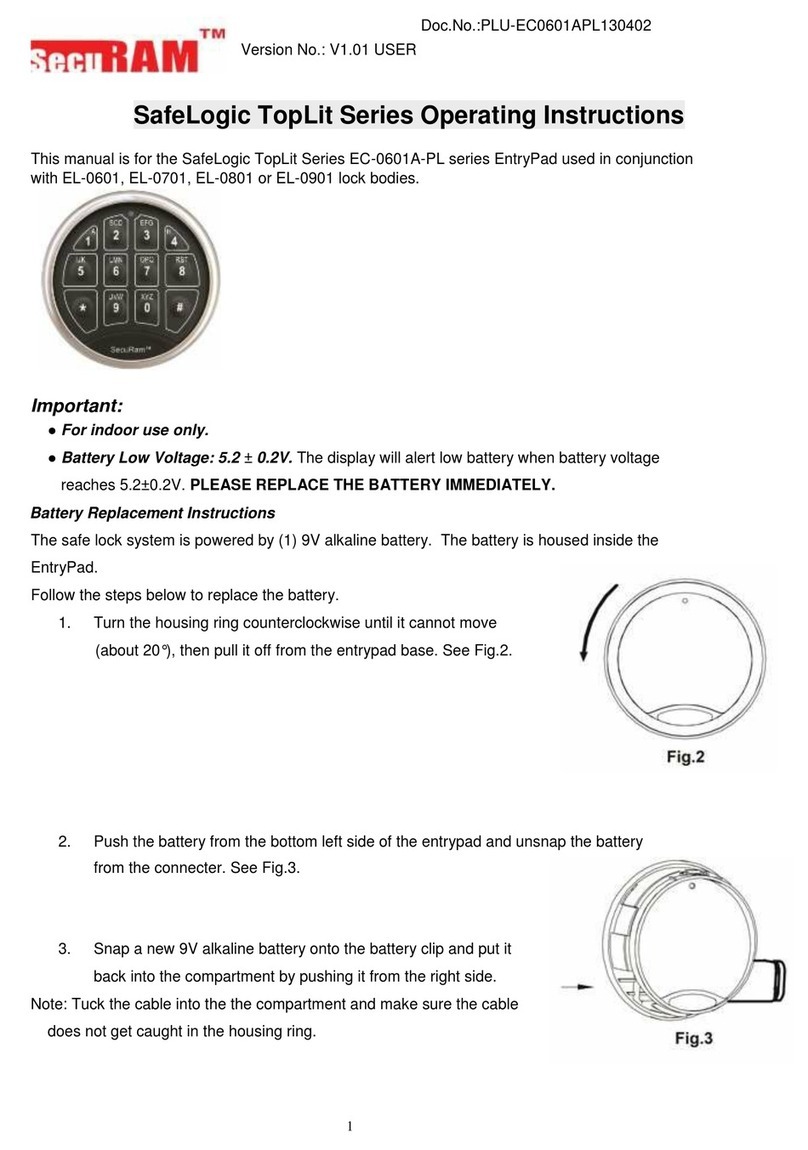
Securam ProLogic L66 User manual

Securam

Securam ProLogic L66 User manual

Popular Lock manuals by other brands

Stock Loks C8722 instruction sheet

Stock Loks

Stock Loks C8722 instruction sheet

Assa Abloy OneSystem 819N Quick manual

Assa Abloy

Assa Abloy OneSystem 819N Quick manual

DigitalHome Smart Lock LS100 user manual

DigitalHome

DigitalHome Smart Lock LS100 user manual

Siemens 3VA9980-0LF20 operating instructions

Siemens

Siemens 3VA9980-0LF20 operating instructions

RCI F2164 Installation

RCI

RCI F2164 Installation

Weiser Aura quick start guide

Weiser

Weiser Aura quick start guide

Hornady Security Alpha Elite owner's manual

Hornady Security

Hornady Security Alpha Elite owner's manual

SmartLock YL-73 user manual

SmartLock

SmartLock YL-73 user manual

Kaba Mauer 70094 Convar F operating instructions

Kaba Mauer

Kaba Mauer 70094 Convar F operating instructions

Alarm Lock Trilogy DL3500 brochure

Alarm Lock

Alarm Lock Trilogy DL3500 brochure

Schlage BE489WB user manual

Schlage

Schlage BE489WB user manual

Assa Abloy INTERLOCK P84166 installation instructions

Assa Abloy

Assa Abloy INTERLOCK P84166 installation instructions

Q-See QSE7F4 user manual

Q-See

Q-See QSE7F4 user manual

LockTech ACCUREADER KW14 quick start guide

LockTech

LockTech ACCUREADER KW14 quick start guide

Simons Voss Technologies LockNode MP Z4 quick guide

Simons Voss Technologies

Simons Voss Technologies LockNode MP Z4 quick guide

Mottura ASTABLOCK 36 Series Assembly instructions

Mottura

Mottura ASTABLOCK 36 Series Assembly instructions

Alarm Lock Networx DL1325NW Mounting Installation Instructions

Alarm Lock

Alarm Lock Networx DL1325NW Mounting Installation Instructions

COMPX MFWSG23000 Dimensional drawing

COMPX

COMPX MFWSG23000 Dimensional drawing

manuals.online logo
manuals.online logoBrands
  • About & Mission
  • Contact us
  • Privacy Policy
  • Terms and Conditions

Copyright 2025 Manuals.Online. All Rights Reserved.