BEST ACCESS SYSTEMS
Indianapolis, Indiana
4
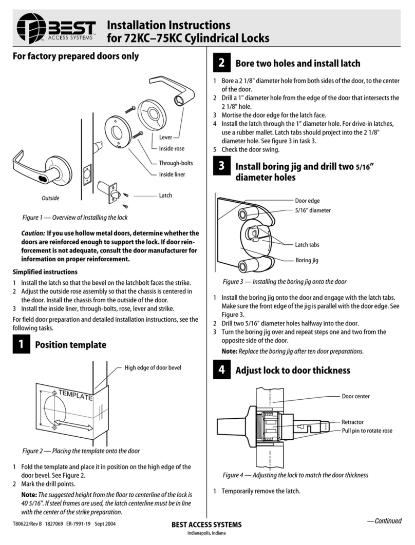
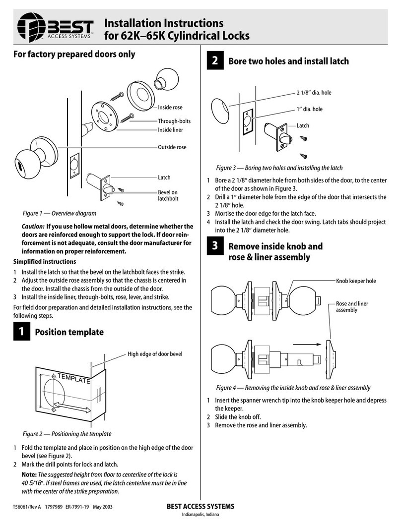
Disassemble inside trim
1
Press the lever keeper with the pin punch or
tool tip in the keeper hole as shown in
Figure 5.
2
Slide the lever off of the sleeve.
3
Press the rose catch with the pin punch or
tool tip and remove the rose.
5
Install outside lever
1
Screw the two stud bolts in the outside rose
assembly.
2
Install the outside lever assembly, correctly
positioning the spindle and through-bolt
stems through the latch.
Note 1:
If the anti-rotation tabs do not seat in
the wood surface, cut out extra clearance so
that they do seat properly.
Note 2:
The outside lever must be in the
UNLOCKED position during installation.
6
Install inside rose
1
Install the inside rose liner by placing it on
the spindle and aligning the two screw
holes closest to the sleeve with the two
through-bolt stems. See Figure 8.
2
Push the rose liner flush against the door.
3
Insert the stem screws and tighten until the
lock is fixed.
4
Slip the inside rose over the sleeve aligning
the open slot on the edge of the rose with
the spring catch on the rose liner as shown
in Figure 6.
5
Tip the rose slightly, pressing the spring
catch (if needed) to allow the rose to snap
onto the liner. Be sure the spring catch pro-
trudes slightly from the slot and the rose is
against the door around the entire edge.
6
Pull on the rose to verify the complete
engagement.
7
Install inside lever
■
Line up the lug in the lever shank with the
slot in the sleeve.
For turnbutton levers:
1
Make sure that the thumbturn is in the
unlocked (horizontal) position as shown in
Figure 9.
2
Pull on the thumbturn to make sure that it
cannot come out. If it does, turn it 180
degrees.
For all levers (including turnbutton levers):
1
Push the lever on completely.
2
Pull on both inside and outside levers to
confirm complete installation.
8
Install strike plate
1
Mortise the door jamb to fit the strike box
and strike plate. Make sure to align the
strike plate and latchbolt centers.
Caution:
The deadlocking plunger of the
latchbolt must not enter the strike plate
opening. The plunger deadlocks the
latchbolt and prevents forcing the latch
when the door is closed. A gap of more
than 1/8” may reduce security and/or
cause improper operation of the latch-
bolt.
2
Insert the strike box and secure the strike
plate with the screws provided.
9
Install core
1
Insert the proper throw member into the
core. Six-pin cores require the number ‘6’
throw member; seven-pin cores require the
number ‘7’throw member.
2
Insert the control key into the core and turn
the key 15 degrees clockwise.
3
Insert the core and throw member into the
lever with the control key as shown in
Figure 11.
4
Turn the key 15 degrees counterclockwise
and remove the key.
Note:
To remove the core reverse these steps.
Figure 5—Pressing the lever keeper
Figure 6—Pressing the rose catch
Figure 7—Installing the outside lever
Press lever keeper
Press catch
Open slot
Spindle
Stud bolts (2)
Through-bolt
studs
Figure 8—Mounting the inside rose liner
Figure 9—Installing the inside lever
Sleeve
Stem screw Rose liner
Screw holes
Thumbturn
Slot in sleeve
Lug in lever shank
Figure 10—Installing the strike box and plate
Figure 11—Installing the core
Door jamb
Strike box
Strike plate
BEST
Core
Throw member
Control key
T56062/Rev –1797905 ER-799 1 -19 Mar 2000
