manuals.online logo
Brands
  1. Home
  2. •
  3. Brands
  4. •
  5. BEST ACCESS SYSTEMS
  6. •
  7. Lock
  8. •
  9. BEST ACCESS SYSTEMS 82T User manual

BEST ACCESS SYSTEMS 82T User manual

BEST ACCESS SYSTEMS
Indianapolis, Indiana
1
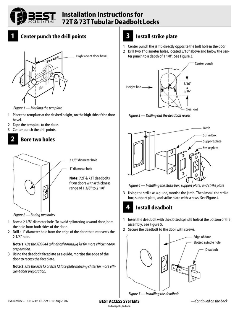
Center punch the drill points
1
Place the template at the desired height, on the high side of the door
bevel.
2
Tape the template to the door.
3
Center punch the drill points.
2
Bore two holes
1
Bore a 2 1/8" diameter hole. To avoid splintering a wood door, bore
the hole from both sides of the door.
2
Drill a 1" diameter hole from the edge of the door that intersects the
2 1/8" hole.
For deadbolts with faceplates
■
Using the deadbolt faceplate as a guide, mortise the edge of the
door to recess the faceplate.
3
Install strike plate
1
Center punch the jamb directly opposite the bolt hole in the door.
See Figure 3.
2
Drill two 1" diameter holes, located 5/16" above and below the cen-
ter punch to a depth of 1 1/8".
Note:
For S1 strike plates only, drill two additional 1" diameter holes
located 15/16" above and below the center punch. Clear out the mate-
rial between the holes.
3
Using the strike as a guide, mortise the jamb and install the strike
box and strike plate as shown in Figure 3.
4
Install deadbolt assembly
For standard deadbolts
1
Insert the standard deadbolt with the slotted spindle hole at the bot-
tom of the assembly as shown in
Figure 4.
2
Secure the standard deadbolt to the door with the faceplate screws.
For drive-in deadbolts
1
Make sure the drive-in deadbolt is in the retracted position.
2
Insert the deadbolt into the door with the slotted hole at the bottom
of the assembly. See
Figure 4.
Figure 1
Positioning and marking with the template
Figure 2
Holes for standard and drive-in deadbolts
High side of the
door bevel
2 1/8” diameter hole
1” diameter hole
Figure 3
Installing the strike
Figure 4
Installing the standard and drive-in deadbolts
Jamb
Strike box
Strike plate
Center punch
Height line
Clear out
5/16”
5/16”
Slotted spindle hole
Drive-in deadbolt
Drive in
Edge of door
Standard deadbolt
Faceplate screws
Installation Instructions
for 82T–83T Deadbolt Locks
T56100/Rev B 1816786 ER-7991-19 May 2000
BEST ACCESS SYSTEMS
Indianapolis, Indiana
3
Using a hammer and wooden block, lightly
drive the deadbolt into the hole until the
face of the deadbolt is flush with the edge
of the door.
5
Install cylinder or cylin-
ders
For 1 3/8”thick doors only
■
Slip the spacer ring behind the outside cyl-
inder and trim assembly as shown
in
Figure 5.
Note:
Use two spacer rings for M function
deadbolts, one behind the outside cylinder
and the other behind the inside cylinder.
For single-keyed cylinder deadbolts
except ‘S’(classroom) functions
1
Extend the bolt with a screwdriver.
2
Install the cylinder and trim assembly with
the spindle in the
vertical
position as
shown in Figure 5.
For non-keyed KL functions
1
Extend the bolt with a screwdriver.
2
Slip the spacer ring behind the outside
rose.
For ‘S’(classroom) function deadbolts
1
Retract the deadbolt with a screwdriver.
2
Install the cylinder and trim assembly with
the spindle in the
horizontal
position.
For double-keyed cylinder deadbolts (‘M’
function)
1
Extend the bolt with a screwdriver.
2
Install each cylinder with its ring and rose
as shown in
Figure 6.
6
Attach inside trim
For standard mounting screws
1
Secure the cylinder to the door with the
clamp plate and mounting screws as
shown in
Figure 7.
2
Break the spindle at the appropriate notch
to suit the installation.
3
Slide the turn knob assembly over the spin-
dle and secure it with the trim screws sup-
plied.
For concealed mounting screws
1
With the inside rose and turn knob unit in
place, put the two mounting screws
through the outside cylinder as shown in
Figure 8.
2
Break the spindle at the appropriate notch
to suit the installation.
3
Screw the mounting screws into the back
of the turn knob unit.
7
Install core or cores
For double-keyed deadbolts or deadbolts
with concealed screws
■
To cover the mounting screw holes, put
the cylinder face into the ring. See
Figure 9.
For all deadbolt locks
1
Put the control key into the core and turn
the key 15 degrees clockwise as shown in
Figure 10.
2
Adjust the throw pins if needed, then put
the core into the cylinder with the control
key.
3
Turn the key 15 degrees counterclockwise
and remove the key.
Caution:
Locks that secure both sides
of the door are controlled by building
codes and the Life Safety Code®. In an
emergency exit situation, failure to
quickly unlock the door from the inside
could be hazardous or even fatal.
Patents
Products are covered by one or more of the
following patents:
U.S. Patents
D290085, 4444034, 4424693, 4386510,
4294093, 4301667, 4655063, 4843852
Other patents pending.
.
Figure 5
Installing the cylinder and trim
assembly
Spindle
Cylinder & trim assy
Extend or retract bolt
with screwdriver here
Spacer ring (1 3/8”
thick doors)
Figure 6
Side view of a double-keyed deadbolt
Figure 7
Standard trim mounting
Figure 8
Concealed trim mounting
Both spindles fit
through slotted
spindle hole
S
p
i
n
dl
e
Clamp plate
Mounting screws
Trim screws
Turn knob assy
Outside cylinder,
ring, and rose
Inside rose
Turn knob unitMounting screw
Figure 9
Installing the cylinder face for double-
keyed deadbolts and deadbolts with
concealed screws
Figure 10
Installing the core on standard
deadbolts
Ring
Mounting screw holes
Cylinder face
Throw pins
Core
Rotate 15 degrees
This manual suits for next models

1

Other BEST ACCESS SYSTEMS Lock manuals

BEST ACCESS SYSTEMS 1E Series User manual

BEST ACCESS SYSTEMS

BEST ACCESS SYSTEMS 1E Series User manual

BEST ACCESS SYSTEMS 7K User manual

BEST ACCESS SYSTEMS

BEST ACCESS SYSTEMS 7K User manual

BEST ACCESS SYSTEMS V Series User manual

BEST ACCESS SYSTEMS

BEST ACCESS SYSTEMS V Series User manual

BEST ACCESS SYSTEMS 62K User manual

BEST ACCESS SYSTEMS

BEST ACCESS SYSTEMS 62K User manual

BEST ACCESS SYSTEMS 9KQ User manual

BEST ACCESS SYSTEMS

BEST ACCESS SYSTEMS 9KQ User manual

BEST ACCESS SYSTEMS 45HQ User manual

BEST ACCESS SYSTEMS

BEST ACCESS SYSTEMS 45HQ User manual

BEST ACCESS SYSTEMS 75KC User manual

BEST ACCESS SYSTEMS

BEST ACCESS SYSTEMS 75KC User manual

BEST ACCESS SYSTEMS 6S User manual

BEST ACCESS SYSTEMS

BEST ACCESS SYSTEMS 6S User manual

BEST ACCESS SYSTEMS 72T User manual

BEST ACCESS SYSTEMS

BEST ACCESS SYSTEMS 72T User manual

BEST ACCESS SYSTEMS 6K Series User manual

BEST ACCESS SYSTEMS

BEST ACCESS SYSTEMS 6K Series User manual

BEST ACCESS SYSTEMS 8KW Series User manual

BEST ACCESS SYSTEMS

BEST ACCESS SYSTEMS 8KW Series User manual

BEST ACCESS SYSTEMS Keypad EZ Remote Unlock User manual

BEST ACCESS SYSTEMS

BEST ACCESS SYSTEMS Keypad EZ Remote Unlock User manual

Popular Lock manuals by other brands

WALDIS PRIMOR 1000 operating instructions

WALDIS

WALDIS PRIMOR 1000 operating instructions

DynaLock 3101B-TJ101 Mounting instructions

DynaLock

DynaLock 3101B-TJ101 Mounting instructions

Ofs Carolina LCK instructions

Ofs

Ofs Carolina LCK instructions

schmersal AZM 161..-33 Series operating instructions

schmersal

schmersal AZM 161..-33 Series operating instructions

Schlage F60 installation instructions

Schlage

Schlage F60 installation instructions

Sargent and Greenleaf 8077 user manual

Sargent and Greenleaf

Sargent and Greenleaf 8077 user manual

COMPX Stock Locks C4153 Dimensional drawing

COMPX

COMPX Stock Locks C4153 Dimensional drawing

Gerda TYTAB ZE-1 Fitting instructions

Gerda

Gerda TYTAB ZE-1 Fitting instructions

STB FL3500 Installer manual

STB

STB FL3500 Installer manual

Stock Loks C8759 instruction sheet

Stock Loks

Stock Loks C8759 instruction sheet

Stanley OmniLock Illustrated parts catalog

Stanley

Stanley OmniLock Illustrated parts catalog

Kaba Mas X-10 installation instructions

Kaba Mas

Kaba Mas X-10 installation instructions

Stanley 3 Series Service manual

Stanley

Stanley 3 Series Service manual

Salto XS4 Mini installation guide

Salto

Salto XS4 Mini installation guide

Videx 4000 Series manual

Videx

Videx 4000 Series manual

Stock Loks C8765 instruction sheet

Stock Loks

Stock Loks C8765 instruction sheet

Zap ACC300 quick start guide

Zap

Zap ACC300 quick start guide

Abloy PLK/A1 Instructions for use

Abloy

Abloy PLK/A1 Instructions for use

manuals.online logo
manuals.online logoBrands
  • About & Mission
  • Contact us
  • Privacy Policy
  • Terms and Conditions

Copyright 2025 Manuals.Online. All Rights Reserved.