BEST ACCESS SYSTEMS 1E Series User manual


CREDITS/COPYRIGHT
©2001–2002 Best Lock Corporation dba Best Access Systems. All rights
reserved. Printed in the United States of America.
Information in this document is subject to change without notice and does not
represent a commitment on the part of Best Access Systems.
This publication is intended to be an accurate description and set of instructions
pertaining to its subject matter. However, as with any publication of this complexity,
errors or omissions are possible. Please call your BEST distributor or Best Access
Systems at (317) 849-2250 if you see any errors or have any questions. No part of this
manual and/or databases may be reproduced or transmitted in any form or by any
means, electronic or mechanical, including photocopying, recording, or information
storage and retrieval systems, for any purpose, without the express written permission
of Best Access Systems.
This document is distributed as is, without warranty of any kind, either express or
implied, respecting the contents of this book, including but not limited to implied
warranties for the publication’squality, performance, merchantability, or fitness for any
particular purpose. NeitherBest Access Systems, nor its dealers or distributors shall be
liable to the user or any other person or entity with respect to any liability, loss, or
damage caused or alleged to be caused directly or indirectly by this publication.
The Life Safety Code is a registered trademark of the National Fire Protection
Association.
Written and designed by Best Access Systems and Avalon Group, Inc., Indianapolis,
Indiana.
T61839 Rev – 1879076 ER7991-6 June 2002

E Series Service Manual iii
CONTENTS
FIGURES VII
GETTING STARTED 1–1
Introduction 1–1
Product family diagram 1–2
Certifications and standards 1–2
Documentation package 1–3
Technical support 1–3
Support services 1–3
Telephone and web technical support 1–3
PARTS FOR 1E SERIES 2–1
Exploded diagrams and parts lists 2–2
Mortise cylinder 2–2
Rim cylinder 2–3
Thumbturn cylinder 2–4
Direct motion cabinet cylinder 2–5
Lost motion cabinet cylinder 2–6
Special mortise cylinder applications 2–7
Dust cover cylinder 2–7
Wrench-resistant cylinder 2–7
Lost motion cylinder 2–7
Hotel shifting cam cylinder 2–8
Non-UL high security cylinder 2–8
Tapered-head cylinder 2–8
Trim parts 2–9
Rim dummy trim 2–9
Mortise dummy trim 2–9
Stamped cylinder rings 2–10

Contents
iv E Series Service Manual
Stamped cylinder ring packages 2–10
Straight cylinder rings 2–11
Wrench-resistant cylinder rings 2–12
Mounting plates 2–13
Tools 2–14
Cam identification 2–15
Straight cams 2–15
Cloverleaf cams 2–19
Cabinet cams 2–20
Roller cams 2–23
Two-point cams 2–24
PARTS FOR 3E SERIES 3–1
Mortise cylinder exploded diagram and parts list 3–2
Trim parts 3–3
Stamped cylinder rings 3–3
Tools 3–3
Cam identification 3–4
Straight cams 3–4
Cloverleaf cams 3–4
Roller cams 3–5
PARTS FOR 5E SERIES 4–1
Exploded diagram and parts list 4–2
Lost motion cabinet cylinder 4–2
Limited motion cabinet cylinder 4–3
Trim parts 4–4
Cylinder rings 4–4
Mounting plates 4–6
Tools 4–6
Cam identification 4–7
SERVICE AND MAINTENANCE 5–1
Replacing parts 5–2
Replacing the standard mortise cylinder 5–2
Replacing the cylinder ring 5–7
Replacing riveted cams 5–8
Replacing the rim cylinder 5–10
Replacing the spindle 5–12
Replacing cabinet cylinders 5–13
Cam rotations for 1E Series cylinders 5–16
Direct motion cabinet cylinders 5–16
Lost motion cabinet cylinders 5–17

Contents
E Series Service Manual v
Cam rotations for 5E Series cylinders 5–18
Lost motion C3 cam rotation 5–19
Lost motion C4A cam rotation 5–20
Lost motion C4B cam rotation 5–21
Limited motion C1 cam rotation 5–22
Limited motion C2A cam rotation 5–23
Limited motion C2B cam rotation 5–24
Troubleshooting 5–25
E SERIES CAMS TABLE A–1
THUMBTURN CAM CONVERSION TABLE B–1
GLOSSARY C–1
INSTALLATION INSTRUCTIONS D–1
INDEX E–1

Contents
vi E Series Service Manual

E Series Service Manual vii
FIGURES
GETTING STARTED
E Series product family diagram 1–2
PARTS FOR 1E SERIES
1E74 mortise cylinder exploded view 2–2
1E72 rim cylinder exploded view 2–3
1E7A4 thumbturn cylinder exploded view 2–4
1E7D4 direct motion cabinet cylinder exploded view 2–5
1E7E4 lost motion cabinet cylinder exploded view 2–6
1E7B4 dust cover cylinder 2–7
1E7C4 wrench-resistant cylinder 2–7
1E7F4 lost motion cylinder 2–7
1E7G4 hotel cylinder 2–8
1E7K4 non-UL high security cylinder 2–8
1E76 tapered-head cylinder 2–8
1E02 rim cylinder dummy trim 2–9
1E04 mortise cylinder dummy trim 2–9
Standard cylinder rings 2–10
Straight cylinder ring (1E-R708 shown) 2–11
Wrench-resistant cylinder ring (1E-R808 shown) 2–12
Mounting plates 2–13
Tools 2–14
PARTS FOR 3E SERIES
3E74 mortise cylinder exploded view 3–2
Cylinder rings 3–3
Tools 3–3

Figures
viii E Series Service Manual
PARTS FOR 5E SERIES
5E7 lost motion cabinet cylinder exploded view 4–2
5E7 limited motion cabinet cylinder exploded view 4–3
Determining the cylinder ring length 4–4
Cylinder ring (R708 shown) 4–5
Mounting plates 4–6
Tools 4–6
SERVICE AND MAINTENANCE
Location of the cylinder set screw 5–2
Removing the mortise cylinder 5–3
Threading the set screw 5–4
Back view of cam in 12 o’clock position 5–4
Reinstalling the mortise cylinder 5–5
Location of the cylinder set screw (view from the edge of the door) 5–6
Removing the cylinder ring (mortise cylinder shown) 5–7
Reinstalling the cylinder ring (mortise cylinder shown) 5–7
Removing the cam 5–8
Reinstalling the cam 5–9
Removing the rim cylinder 5–10
Figure-8 opening 5–11
Reinstalling the rim cylinder 5–11
Removing the spindle 5–12
Reinstalling the spindle 5–12
Securing the spindle 5–12
Location of cam screws (5E Series cylinder assembly shown) 5–13
Reinstalling the cabinet cylinder (5E Series cylinder assembly shown) 5–15
Groove pins installed for limited motion rotations 5–18
Groove pins installed for lost motion rotations 5–18
5E Series lost motion C3 cam rotation 5–19
5E Series lost motion 4A cam rotation 5–20
5E Series lost motion 4B cam rotation 5–21
5E Series limited motion C1 cam rotation 5–22
5E Series limited motion C2A cam rotation 5–23
5E Series limited motion C2B cam rotation 5–24
THUMBTURN CAM CONVERSION TABLE
C4 standard cam and equivalent C140 thumbturn cam B–2

E Series Service Manual 1–1
1 GETTING STARTED
INTRODUCTION
The E Series Service Manual contains essential
information to help you maintain your E Series
product. This manual includes information for
1E Series, 3E Series, and 5E Series 7-pin cylinder
products only.

Getting Started
1–2 E Series Service Manual
PRODUCT FAMILY DIAGRAM
CERTIFICATIONS AND STANDARDS
■The 1E7J4 high security cylinder is listed by Underwriter’s
Laboratories when used with 36H/37H mortise locks.
■The 1E74 mortise cylinder complies with ANSI/BHMA, Grade 2
standards when used with 30H Series mortise locks and the
1CD core.
■The 1E74 mortise cylinder complies with ANSI/BHMA, Grade 3
standards when used with the standard 1C core.
Figure 1.1 E Series product family diagram
1E mortise cylinder 1E high security cylinder 1E cabinet cylinder 1E thumbturn cylinder
3E mortise cylinder1E rim cylinder 5E cabinet cylinder

Getting Started
E Series Service Manual 1–3
DOCUMENTATION PACKAGE
The following resources are available to help you with the installation,
start-up, and maintenance of your BEST E Series product.
These documents can be ordered separately from the product:
TECHNICAL SUPPORT
Support
services
When you have a problem with an E Series product, your first resource
for help is the E Series Service Manual. If you cannot find a satisfactory
answer, contact your local BEST Representative.
Telephone and
web technical
support
A factory-trained Certified Product Specialist (CPS) is available in your
area whenever you need help. Before you call, however, please make
sure you are where the E Series product is, and that you are prepared to
give the following information:
■what happened and what you were doing when the problem arose
■what you have done so far to solve the problem.
Best Access Systems Representatives provide telephone technical
support for all E Series products. You may locate the representative
nearest you by calling (317) 849-2250 Monday through Friday, between
7:00 a.m. and 4:00 p.m. eastern standard time; or visit the web site,
www.BestAccess.com.
Documentation Title Doc. No.
BEST Installation Instructions for 1E Mortise Cylinders T61781
BEST Installation Instructions for 1E Rim Cylinders T61971
H Series Service Manual T61964
Best Adaptation & Equivalent List (8th edition) B120–1
Core and Key Service Manual T35527

Getting Started
1–4 E Series Service Manual

E Series Service Manual 2–1
2 PARTS FOR 1E SERIES
The following pages contain exploded diagrams that
show all field serviceable parts for common 1E Series
mortise, rim, and cabinet cylinders. This chapter also
contains diagrams of special application mortise
cylinders, diagrams of trim and other miscellaneous
parts, and diagrams of common cams.

Par
t
s for 1E Series
2–2 E Series Service Manual
EXPLODED DIAGRAMS AND PARTS LISTS
MORTISE CYLINDER
Figure 2.1 1E74 mortise cylinder exploded view
Item Part no. Qty. Description
1 A06831 1 Spacer for 6-pin cores
2 A40095 2 Throw pin
3 A10390 1 Throw plug
4 A10391 1 Stamped head
5 C34075 1 7-pin cylinder
6 See page 2–10 1Cylinderring
7 See page 2–15 1Cam
†(C4 shown)
† Specify cylinder length when ordering cams.
Cylinders 2 inches or longer require a thumbturn cam.
See Appendix B for available thumbturn cams.
8 A34123 1 Set screw
1
3
5
2
8
4
6
7

Par
t
s for 1E Series
E Series Service Manual 2–3
RIM CYLINDER
Figure 2.2 1E72 rim cylinder exploded view
Item Part no. Qty. Description
1 A06831 1 Spacer for 6-pin cores
2 C00121 1 7-pin cylinder
3 See page 2–10 1 Cylinder ring
4 A40110 1 Throw plug assembly
5 A40100 1 Spindle
6 B40109 1 Throw plug retainer
7 A14553 2 Retainer screw
8 C13910 1 Clamp plate
9 A08544 2 Mounting screw
1
3
5
2
6
7
8
4
9

Par
t
s for 1E Series
2–4 E Series Service Manual
THUMBTURN CYLINDER
Figure 2.3 1E7A4 thumbturn cylinder exploded view
Item Part no. Qty. Description
1
not shown
B61572
A24046
1
1
ADA thumbturn
Non-ADA thumbturn
2 A03612 1 Spring plug
3 A18033 1 Spring
4 B04781 1 7-pin cylinder
5 See page 2–10 1 Cylinder ring
6 See page B–2 1Cam (C413 shown)
7 A04838 2 Cam screw
4
1
6
2
3
7
5

Par
t
s for 1E Series
E Series Service Manual 2–5
DIRECT MOTION CABINET CYLINDER
Figure 2.4 1E7D4 direct motion cabinet cylinder exploded view
Item Part no. Qty. Description
1 A06831 1 Spacer for 6-pin cores
2 A00539 2 Throw pin
3 A07544 1 Throw plug
4 B07547 1 7-pin cylinder
5 See page 2–10 1 Cylinder ring
6 A00836 1 Nut
7 A04460 1 Throw plug retainer
8 See page 2–20 1Cam
†(C228 shown)
† See page 5–16 for cam rotations.
9 A07542 2 Cam screw
1
3
5
2
4
9
7
8
6

Par
t
s for 1E Series
2–6 E Series Service Manual
LOST MOTION CABINET CYLINDER
Figure 2.5 1E7E4 lost motion cabinet cylinder exploded view
Item Part no. Qty. Description
1 A06831 1 Spacer for 6-pin cores
2 A07986 1 Throw member assembly
3 A07993 1 7-pin cylinder
4 See page 2–10 1 Cylinder ring
5 A00836 1 Nut
6 B40412 1 Cam stop pin
7 See page 2–20 1Camwithdrivepin
†(C229 shown)
† See page 5–17 for cam rotations.
8 A07988 1 Cam driver
9 A07954 1 Washer
10 A07956 1 Cam screw
1
3
7
2
5
6
8
910
4

Parts for 1E Series
E Series Service Manual 2–7
SPECIAL MORTISE CYLINDER APPLICATIONS
Dust cover cylinder
Wrench-resistant
cylinder
Note: See page 2–12 for wrench-resistant cylinder rings.
Lost motion cylinder Note: Specify cylinder handing when ordering (for example,
“RHI” = right hand, inside door).
Figure 2.6 1E7B4 dust cover cylinder
Figure 2.7 1E7C4 wrench-resistant cylinder
Figure 2.8 1E7F4 lost motion cylinder

Parts for 1E Series
2–8 E Series Service Manual
Hotel shifting cam
cylinder
Non-UL high
security cylinder
Note: To order the 1E7J4 high security cylinder listed by Underwriters
Laboratories (UL), contact your BEST Representative.
Note: High security cylinders require long blade keys for operation.
Tapered-head
cylinder
Figure 2.9 1E7G4 hotel cylinder
Figure 2.10 1E7K4 non-UL high security cylinder
Figure 2.11 1E76 tapered-head cylinder
This manual suits for next models
17
Table of contents
Other BEST ACCESS SYSTEMS Lock manuals
BEST ACCESS SYSTEMS
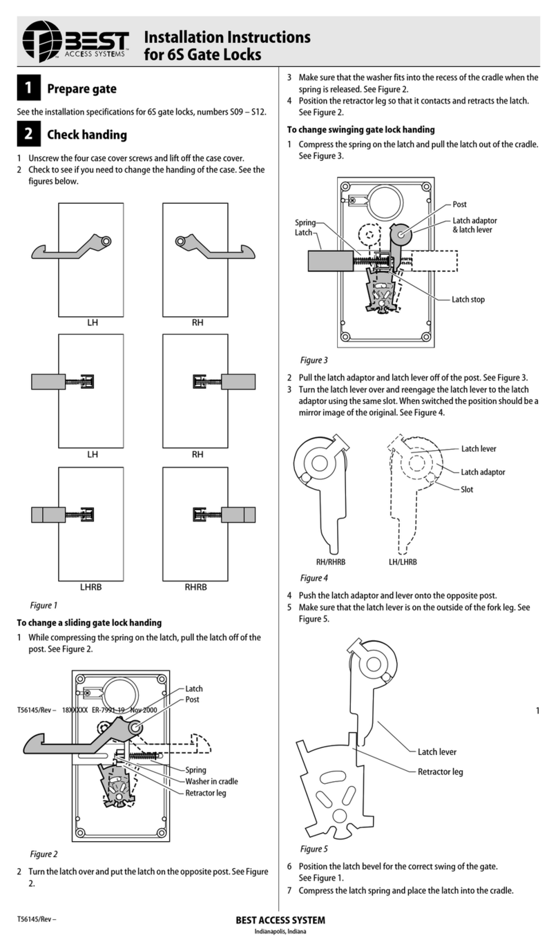
BEST ACCESS SYSTEMS 6S User manual
BEST ACCESS SYSTEMS
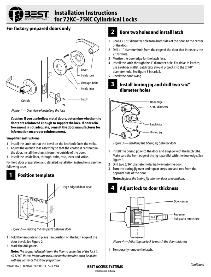
BEST ACCESS SYSTEMS 75KC User manual
BEST ACCESS SYSTEMS
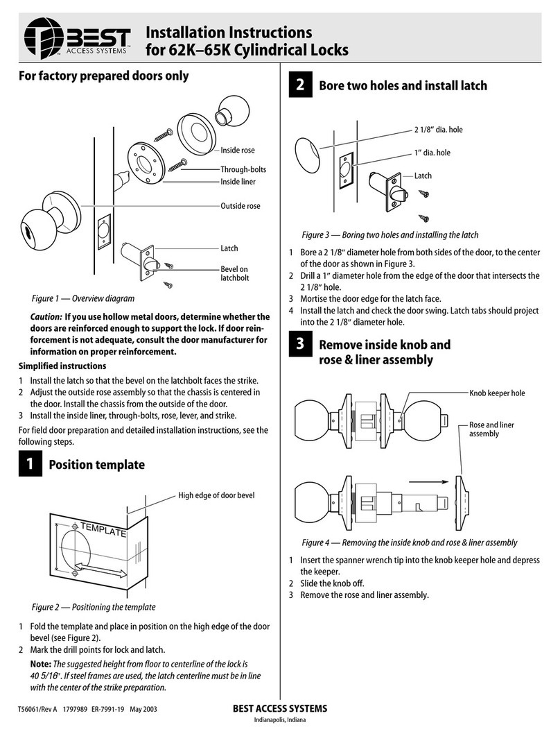
BEST ACCESS SYSTEMS 62K User manual
BEST ACCESS SYSTEMS
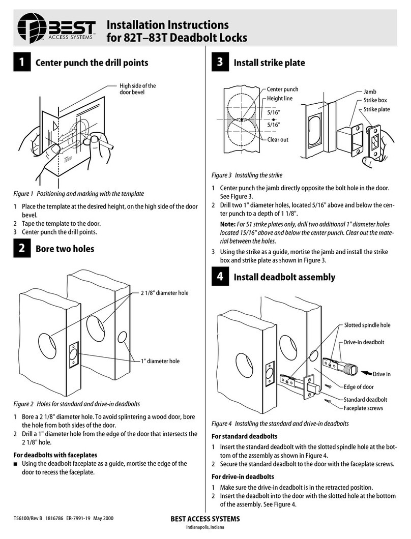
BEST ACCESS SYSTEMS 82T User manual
BEST ACCESS SYSTEMS
BEST ACCESS SYSTEMS 9KQ User manual
BEST ACCESS SYSTEMS
BEST ACCESS SYSTEMS 8KW Series User manual
BEST ACCESS SYSTEMS
BEST ACCESS SYSTEMS Keypad EZ Remote Unlock User manual
BEST ACCESS SYSTEMS
BEST ACCESS SYSTEMS 7K User manual
BEST ACCESS SYSTEMS
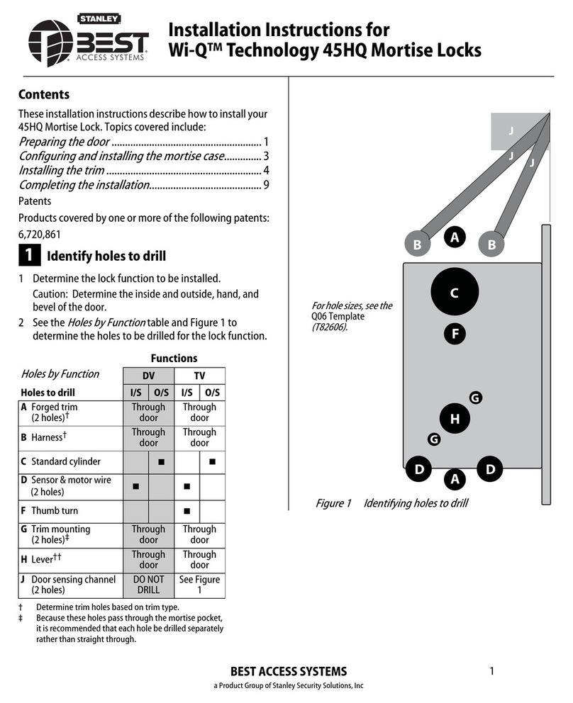
BEST ACCESS SYSTEMS 45HQ User manual
BEST ACCESS SYSTEMS
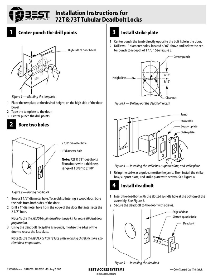
BEST ACCESS SYSTEMS 72T User manual
