Best Tugs BRAVO 5 User manual

BRAVO
USER MANUAL
5, 8, 12, & 18
Best Tugs
Because Your Pla ne Deserves It

252 West 3560 North
Spanish Fork, UT 84660
800.914.2003
INTRODUCTION
At Best Tugs™, we pride ourselves on building the most innovative
and advanced tugs in the world. We work diligently to ensure that
the quality and workmanship of your tug exceeds your expectations
and are confident that you will see the difference in every part of
your Best Tugs™experience.
We designed this guide to provide you the information needed to
make your experience even better… and while we are confident that
this guide will answer your questions, we are always here to chat
with you on the phone. You can reach us at 800-914-2003.
Thank you again for choosing Best Tugs™.
Best Aviation
Products

1
Please read these instructions
before beginning.
For any questions
call us at 800.914.2003
Tools Needed:
• Phillips Head
Screwdriver
(Drill/Impact is easiest)
• 7/16 Socket
1. The lid is spray-painted with a red “1”.
Remove the screws marked with red
paint. Remove the top lid from the
crate.
2. The end panel is spray-painted with a
red “2”. Remove the screws marked
with paint. Remove the panel from
the crate.
3. Remove the plastic wrap from
around the Control Arm. Remove
the L-Handle Pin from the control
arm BEFORE lifting the control arm
(FIG 1). Rotate the Control Arm into
the lowest operating position (FIG
2). Insert L-Handle Pin until the pin
is visible from both sides. See page
8 for more instructions on adjusting
the Control Arm.
4. On the lateral sides of the crate,
marked with a red “3” - Remove the
screws marked with red paint. These
screws are in a 2x4 board, which is
holding the control arm and tires
in place. NOTE: Make sure to hold
the boards as you remove screws to
keep them from falling onto the tug’s
cover.
5. Cut the strap holding the cardboard
box in place. This box holds the
accessories for your tug. Remove the
box from the crate.
UNCRATING INSTRUCTIONS
FIG 1
11
22
33
FIG 2
Note: Foam filed tires
have a screw in the tire
from the factory. It is safe
to remove the screw.

2
6. Using the end of the crate, stack the
2x4’s (step 4) on top of each other, as
illustrated. (FIG 3)
7. Place the removed end wall with the ½”
plywood resting on the 2x4’s to create a
ramp. (FIG 4)
NOTE: The B5 comes with two (2)
2x4 boards in the crate, while the
B8 and B12 come with three (3). Use
the third 2x4 board to support the
ramp, as shown in FIG 4 for the more
substantial B8 and B12 models. The third
board is not necessary for B5. If you
have a painted floor, we recommend
performing this step outside of the
hangar to avoid any possible scuffs or
scratches.
8. Turn the tug on by rotating the red
E-Stop on the end of the control panel
clockwise and pushing the master
switch to the “on” position.
9. Set the direction to “PULL” and slowly
twist the throttle to drive your tug out
of the crate. See page 11 of your User
Manual for further instructions on how
to operate tug safely.
UNCRATING INSTRUCTIONS
Continued
FIG 3
FIG 4
Please Email cool pictures of
your tug and plane to sales@
besttugs.com. You may see it
on our website or social media.
(By sending images, you expressly
permit us to use these images for
marketing purposes.)
A couple notes:
The twisting and lock-
ing slides are attached
to the QLF. They are list-
ed for reference purpos-
es. Be sure to remove
the L-Handle Pin before
rotating the control
arm into the operating
position. The contents
in your crate may vary
from the illustrations.
First Use
If you are using an Easy Load or Lazy Susan
configuration: the tug comes from the factory
with the tire cradle in a loaded position. Unlock
the hook and then physically pull the locking
hook back to release the cradle before physically
moving the ramp to the loading position. Note:
Before each use, double-check your loading
tray. Repeat the step of manually lowering the
ramp if needed.

3
External Charger
WHAT’S IN THE CRATE?
Cup Adapters
Air Hose and Pressure Gauge
Jump Start Cords
Twisting Slide Locking Slide
Items Depending On Aircraft
or Options on Tug
Standard Items
L-Handle Pin
(in base of control arm)
Wheel Chock Kit
Carabiner, Axle Strap, RGA Pin
Quick Lock Fork (QLF)

4
CONTROL PANEL FUNCTIONS
1. Emergency Stop Switch
Rotate clockwise to power on,
push in to turn off. CAUTION! Do
not turn off while in motion, un-
less an emergency stop is needed,
this aggressively shuts down the
system and locks parking brake.
2. Master Switch
Turns tug on and off. NOTE: Tug
will not turn on if E-Stop is de-
pressed.
3. Multifunction
Note: this switch controls mutually
exclusive options; it has three func-
tions unless you only have the EZ
Load. The Lazy Susan is a rotatable
EZ Load.
EZ Load
(Two Position Switch)
Up/Load Locks the cage in the
load position. Down/Unload re-
leases the cage
The Lazy Susan
(Three-Position Switch) Rotate/Up
releases the Lazy Susan turntable
The EZ load cage is also locked.
Load allows locking the rotation
when the pin aligns and locks
the EZ Load. Unload/Down the
turntable is locked, and the cage is
released.
Heli/Trailer Lift/High Lift
(Two Position Switch) controls up/
down motion. Motion starts when
you push on the switch and stops
when you release the switch, or
the Lift has achieved max travel up
or down. Note: When using the
High Lift: do not move your plane
in the elevated position while
turning.
4. Battery Charge Status
Recharge your tug when power
indicates 70% (while tug is at rest.)
When charging, turn your tug off.
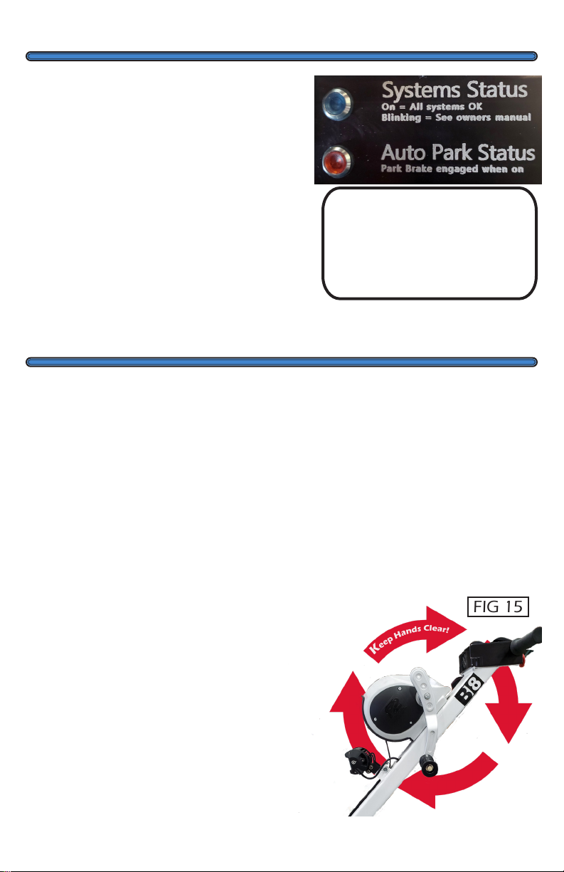
5. System Status Indicator
See Error Code Translations on
page 14 for flashing light transla-
tions.
6. Auto Park Indicator
The red light indicates that the
parking brake is set. The brake
engages when the tug comes to a
stop and remains “in-park” when
the system is powered down.
Note: Always use wheel chocks
7. Direction Control
Push/Pull
8. LED LIGHT (optional)
Make sure this switch is off while
the tug is charging.
9. Air Compressor (optional)
When hooking up the included
hose: Insert the air hose into the
fitting while pulling the sleeve on
the fitting away from the brass
elbow connection. Release the
fitting to lock air hose into place.
10. High/Low Setting
Use “HIGH” for maximum speed,
typically used for long-distance
movements. Use the “LOW” set-
ting when maneuvering in tight
or restrictive areas for better con-
trol and safety. No damage will
occur if the HIGH/LOW setting is
changed while in motion.

5
3
2
79
810
44
55
6
1

6
Please familiarize yourself with
how long it takes for your tug
to ramp up/down and stop;
the“coast” when slowing
is due to the software that
protects your nose gear from
unnecessary damage and
stress. Take the time to get used
to this feature and be aware of
it as you move your aircraft.
INITIAL USE
Adjusting the Control Arm
Your tug arrives fully assembled.
Before first use, set the control
arm to your preferred height. To
do this, be sure you have a good
hold on the control arm to make
sure it doesn’t fall onto the cover,
remove the L-Handle Pin at the
base of the control arm and
rotate the arm (FIG 5) until it is
at your preferred angle. (Most
users lower it to the bottom
position.)
Once you have decided on the
angle, line up the holes on the
base bracket with the holes on
the base of the control arm and
insert the L-Handle Pin until it is
visible from both sides. (FIG 6)
We strongly recommend using
your tug without an aircraft
attached to get used to the
controls and movements; this
is a very user-friendly system,
but it can take a bit of practice
to get familiar with initially.
Change the drive direction
(PUSH/PULL),
vary the speed by
slowly twisting the throttle as
you begin moving.
Make sure
you are comfortable with the
throttle, maneuverability, and
functionality of the tug before
moving your plane.
FIG 5
FIG 6

7
EZ Load/ Lasy Susan
The Cage on the Ez Load/Lazy
Susan needs to be adjusted to fit
your specific tire. After you load
your plane, adjust the width by
adjusting the two sliders on the
bottom of the Cage so that they
are close to the tire’s sidewalls.
Remove the pins and adjust the
sliders to the nearest hole, then
put the pins back in.
The size of the wheel that can be
loaded can be adjusted. Remove
the thumbscrews and adjust the
Cage so that it fits closely to your
tire diameter. We designed the
Cage to resist letting your tire
pop out of the Cage. If you have
not adjusted this feature, a tire
could pop out of a loosely fitted
Cage.
Warnings
Check the plane’s surroundings,
remove any obstructions, verify
that your path is clear, and
your propulsion systems (prop),
wings, and tail, clears. Please
verify that your wheel is secure
on the tug, including strapping
it down. Finally, remove the
wheel chocks. You are ready
to move your plane. Check
your plane’s POH to verify the
maximum turn radius for your
particular nose gear. The tug
can turn your plane at an angle
that may exceed the nose gear’s
maximum turn radius. Best
Tugs™assumes no responsibility
for any damage caused by
the tug operator misusing the
equipment. As the operator,
you have the responsibility
to be familiar with your tug,
your plane, and their specific
limitations.
Note: E-Stop means
EMERGENCY STOP. Not
power off, not stop my tug
from moving—It means Stop
now—I don’t care if my tug and
my plane’s landing gear are
damaged, because my plane
going through the hanger wall,
or trapping your body against
the hanger wall, is much more
expensive to repair.
When you shut down the tug
with the E-Stop, all that energy
in the motor controller has to
go somewhere, and it does—
destroying the controller over
time.
INITIAL USE
Continued
8
FIG 9
FIG 7
FIG 8
First Time Set Up (QLF/Wheel Chock Kit)
NOTE: Quick Lock Fork and Wheel Chock Kit
ARE NOT USED TOGETHER
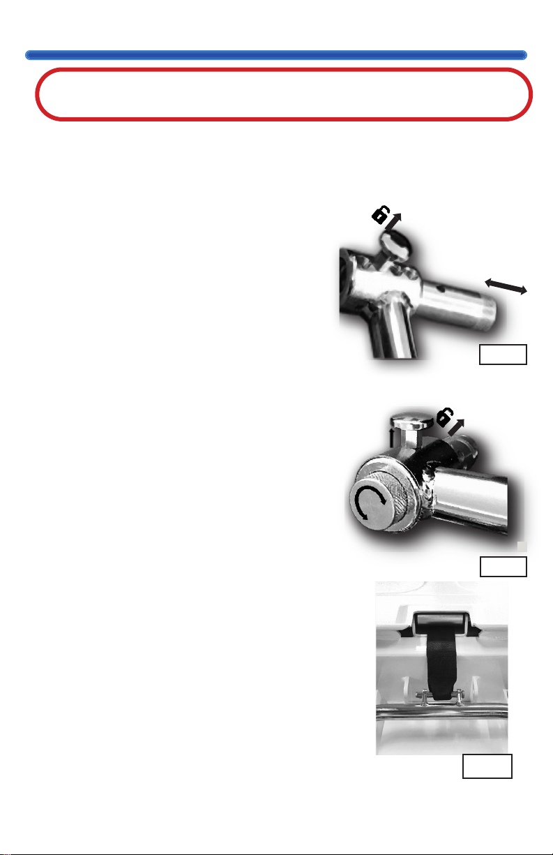
Setting Up the Quick Lock Fork
If equipped with the standard ramp
TIP: It is easier to set up your QLF
if you give yourself plenty of slack in the strap.
1. Right Fork - Push the spring-loaded locking
slide on the right fork of the QLF to the left
until it locks into place. It is locked when the
slide does not return to the open position
on its own. (FIG 7) To release the slide, lift
the drop pin and allow it to return to its
original position.
2. Place the QLF over/in the nose gear
connection.
3. Left Fork - Lift the drop pin on the left fork
and rotate the slide until it fits firmly against
the nose gear. (FIG 8) The less slop and
wiggle, the better. Once the slide is fitting
snugly, release the drop pin and continue
twisting until it falls into place to lock the
slide. See FIG 10 and FIG 11.
Setting Up Wheel Chock
The wheel chock drops into the loading
tray between the two brackets. Line up
the holes on the RGA with the bracket
holes in the loading tray and insert the
pin. Make sure both ends of the pin are
visible and fully inserted. (FIG 12)

9
Pin Improperly Set
FIG 10
First Time Set Up (QLF/Wheel Chock Kit)
Continued
Switching from
Wheel Chock to QLF
Pull the long pin and remove the wheel
chock from the loading tray and take the
carabiner off the tow strap. Take the winch
strap in one hand and the QLF in the other.
Take the QLF pin out of its hole by pushing
the springing wedge down and removing
the pin. Slip the winch strap onto the pin
and push the pin to the original position.
(FIG 9) Line the strap loop up with the QLF
pin holes then push the pin back
through the strap and QLF holes. Ensure
the spring wedge holds the pin in place.
Now that your wheel chock is set up for
your specific plane, you are ready to winch
it into place and move your aircraft.
DO NOT USE QUICK LOCK FORK
AND THE WHEEL CHOCK KIT
AT THE SAME TIME
Pin Properly Set
FIG 11
FIG 12
See BestTugs.com for instructional videos on loading.

10
STRAP INSTRAP IN
STRAP INSTRAP IN
STRAP OUTSTRAP OUT
STRAP OUTSTRAP OUT
B5 Winch
FIG 13
Loading Your Plane (Standard Ramp)
STRAP INSTRAP IN
STRAP INSTRAP IN
STRAP OUTSTRAP OUT
STRAP OUTSTRAP OUT
B9 / B12 Winch
FIG 14
Note: If you are comfort-
able with your throttle,
you can choose to winch
the plane onto the tug
while very slowly driving
the tug forward, which
makes winching easier.
Keep wheels chocked if
you decide to use this
method.
Double-check your attachments to
make sure they are correctly attached,
and the setup steps followed.
1. Chock aircraft mains. Position tug
with nose wheel centered on the
ramp. Until you are comfortable
with the tug’s operation, turn the
tug off for the safest loading.
2. Put the winch in neutral/reverse
and pull enough slack in the strap
to attach QLF for wheel pant
planes or axle strap for retractable
gear aircraft.
3. Before you begin winching, flip
the switch (FIG 13) on the B5
winch to the forward position
(counter-clockwise (FIG 14) for B8
and B12-18) and winch the plane
onto tug’s loading tray.

11
Check the surroundings of the
plane, remove any obstructions,
including the wheel chocks.
Make sure the tug is in proper
mode (PUSH/PULL) then twist
the throttle to start moving.
Make sure you familiarize
yourself with how long it takes
for your plane to ramp up/down
and stop.
When slowing, the “coast”
is due to the software that
protects your nose gear from
unnecessary damage and stress.
(Note: E-Stop overrides the soft
auto-stop feature. You could
damage your plane and or tug)
Take the time to get used to the
soft auto stop feature and be
aware of it when moving your
aircraft.
We strongly recommend
moving your tug without aircraft
attached to get used to the
controls and movements. As you
are moving your plane, be sure
your nose gear can handle the
turns you are taking.
As the operator, you are
responsible for knowing the
limitations of your specific
aircraft.
Moving Your Plane
12
Parking
Unloading Your Plane (Standard Ramp)
Your tug has an automatic parking
brake that engages when you stop
your tug. A red light on the control
panel lights up to show the brake
has been appropriately set. When
you are ready to move, rotate the
throttle, and the brake disengages
automatically. NOTE: Tug’s parking
brake acts as a secondary brake,
always use wheel chocks to park
your aircraft safely.
If anything ever looksIf anything ever looks
wrong or like it maywrong or like it may
damage your aircraft,damage your aircraft,
please call us.please call us.
800.914.2003800.914.2003
Make sure the tug is in line with
the plane. Chock the aircraft
mains.
Crank the winch handle slightly
to release stress on winch direc-
tion selector; switch to unload/
neutral.
Select “PULL” on the control pan-
el and slowly drive tug
away from aircraft.
CAUTION
The winch handle rotates quickly
as your plane unloads from the
tug, keep hands clear (FIG 15)
Leave the slack left from unloading
the plane unspooled; this leaves
the attachment/strap ready to be
attached for your next flight.
FIG 15
Always use wheel
chocks when loading
and unloading your
plane.

13
Lazy Susan/EZ Load Operation
Your Cage can and should be
adjusted to more tightly fit your
wheel. Both the diameter (thumb-
screws) and width (slider) can be
adjusted. See Initial Use on page 7
for set up instructions.
If you have a Lazy Susan, lock the
rotation before loading or unload-
ing. Locked, the Lazy Susan now
behaves as an EZ Load. Be sure
your tug and aircraft are in line
with each other before loading/
unloading to avoid damage to your
tug/aircraft.
To lock the Lazy Susan so it cannot
rotate, engage the locking mecha-
nism by selecting Load or Unload/
Down, depending on what you
are going to do, and line up the
plane and tug until the locking
mechanism engages. You can not
unload a plane until the Lazy Susan
is aligned AND locked. To allow the
Lazy Susan to rotate—push Rotate/
UP, to disengage the locking mech-
anism.
In the Unload/Down switch posi-
tion (hold the silver button down
on older models), the EZ load
locking device releases when the
weight of the plane’s wheel shifts
from contacting the ramp and
presses against the back of the
Cage. Note: this is a safety feature
to prevent the tug from releasing
while you are pulling your tug.
Loading:
Make sure the ramp is down. If it
is not in the down position, select
Unload/Down and manually lower
the ramp. Drive the tug under your
wheel. When your plane is loaded
correctly, the ramp automatically
locks into the upright and locked
position.
Unloading:
Select Unload/Down on the rocker
switch (silver button on older mod-
els) to allow your plane to unload.
Carefully move the tug towards the
chocked aircraft; this causes the
nose wheel to contact the back of
the Cage, relieving pressure from
the ramp and disengages the lock-
ing device. Then as you pull away
from the plane, the tire pushes the
ramp open.
An advanced maneuver is; while
moving the plane towards you,
press the Unlock on the rocker
switch (silver button on older mod-
els) to allow the locking device to
release when the ramp pressure is
removed, then reverse the throttle.
The tug’s autothrottle allows the
plane to continue to move towards
you for a moment during the
autothrottle’s slow-down/reverse.
That lets your plane press against
the back of the Cage, removing the
pressure against the locking device,
and then you can pull the tug from
under your wheel.
14
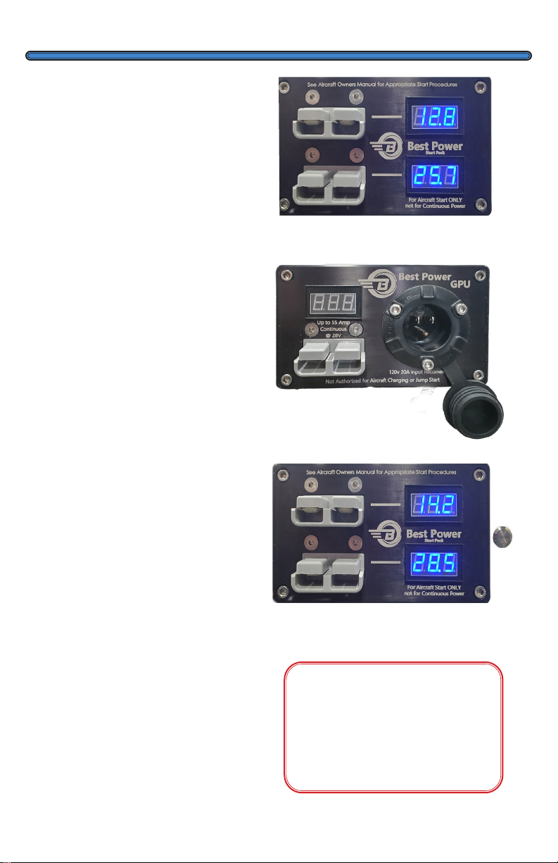
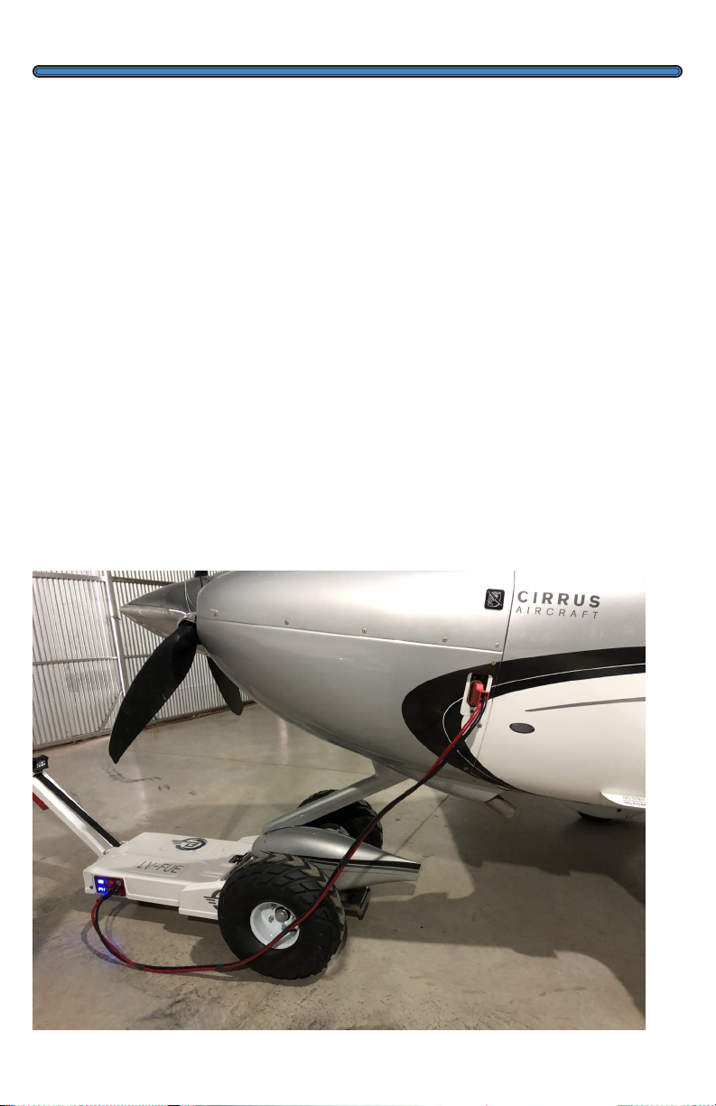
Power Options
JumpStart: Provides High
cold-cranking amps to assist in
starting your engine (12 Vdc and 24
Vdc). This option uses power from
your tug’s batteries to assist your
aircraft’s batteries when starting
your plane. Note: Even when the
tug is off, the JumpStart panel is
live! (Although the readouts won’t
show until the tug is on.)
GPU: The Ground Power Unit is
used to power your avionics and
other lower power demand systems
in your aircraft from the standard
110 Vac wall connection. You have
28.5 Vdc at 25/50 Amps. Note: Do
not use the GPU to power air condi-
tioning or pitot tubes. Warning: bat-
tery damage is possible—the GPU
should not be used to charge either
the tugs or the aircraft’s batteries!
JumpStart + Boost: Press the
silver button to the right of the
JumpStart JumpStart panel, and the
tug gives you thirty minutes (from
the time you pushed the button.)
with over 28 Volts from the GPU
and all those amps from the batter-
ies providing power to the plane.
The disadvantage of using only the
JumpStart option is that you are us-
ing the tugs batteries that discharge
with time, and some planes require
over 28 Volts before they can rec-
ognize the external power source.
With the JumpStart plus Boost, you
can combine both sources of power
for an excellent source of current
at the correct voltage to start your
plane.
GPU PANEL
W/ EXPOSED 110 VAC PORT
JumpStart Panel
JumpStart Panel
w/Silver Boost Button
Plug the cable into your plane
first! Which service your plane
gets depends on which pow-
er panel you insert the cable.
See page 16

15
Tighten the wheel lugs once
a quarter to 70 ft/lbs. The
recommended tire pressure for inner
tube equipped tires is 45 PSI. The
caster wheel needs to be re-greased
every two years for continuous use.
Tighten chains every 12 months for
safe operation. To tighten chains,
remove the six (6) screws around
the perimeter of the cover, loosen
five (5) bolts on the motor mount.
Using a pry bar, tighten the chains by
pushing against the axle until there
is little to no slack in the chains, while
keeping chain tension, re-tighten
bolts. If you have any questions about
this process, give us a call.
Winch straps (on tugs equipped with
winches): Before each use, check
straps for damage or loose stitching.
If the strap is damaged, replace it
before use. Replace your winch straps
annually; there is cumulative UV
and oxidation damage that can be
invisible to the eye.
Best Tugs™ will replace your strap
once a year for free—as long as you
own your tug. Just pay shipping and
handling. Call sales at 800.914.2003
to order; exclusions
apply.
The Lazy Susan option needs to
have the central bolt tightened and
moving parts lube with lightweight
oil annually. It is found under the
Romeo and centered under the
Lazy Susan. Failure to maintain this
may cause the failure of the bearing
ring. Loosen the locking nut and
tighten the central nut until tight,
but not so tight that the Lazy Susan
cannot rotate. Re-tighten the locking
nut after you have completed the
adjustments.
If the Lazy Susan’s locking
mechanism fails to engage,
disconnect the wires (unplug the
pins) of the solenoid (Left side
when looking from the ramp side
and golden in color) and twist
counterclockwise to remove. On
older models, manually align the
Lazy Susan until you find the only
opening. Clean the opening below
of oils and debris. Replace the
solenoid and re-plug in the wires.
Store your tug in an area that is
dry and safe from the elements.
Electrical systems are not affected
by limited exposure to rain and
snow. We do not recommend
extended exposure.
If you do not plan on using your
tug for an extended period, leave
your tug plugged in so the smart
charger can take care of the
battery.
Always turn off your tug and
accessories.
Storage
Maintenance
16
Battery Care
Your tug has a smart charger
with trickle charge and battery
maintenance cycles. To charge,
plug the charger cord into the
tug, then the power cord into
a standard power outlet. You
cannot overcharge when using
the included charger.
Always turn off the master
switch when charging.
We suggest charging your tug
when the battery falls below
around 70% (at rest) for optimal
battery life (for sure before 30% at
rest). Note: The tug continuously
and instantaneously calculates
the state of charge, which is why
the percentage fluctuates while
moving your plane. We have seen
as low as a 10% charge displayed
when using a fresh battery and
moving a heavy plane. To read
the resting battery’s charge,
leave the tug at rest for at least
60 seconds. We have seen a 10%
drop from freshly charged just by
moving the tug in and out of the
hanger. The discharge rate is non-
linear.
If you notice shorter times needed
between charges, your batteries
are beginning to wear out.
Lead Acid batteries are
surprisingly delicate—damaged
by direct and indirect effects:
environmental, user induced,
misapplication, and on and on.
For instance, charging with
a voltage above 14.4 volts or

17
12 Volt 35 AH Sealed AGM Battery.
Battery Care
Continued
Acceptable brands include Duracell, UPG, Bright Way Group, Panasonic,
Interstate, and others. (The previous are registered trademarks of the respective companies.)
Length: 7.68 in
Width: 5.12 in
Height: 7.09 in
Volt age: 12
Lead Acid Type: Deep Cycle
Capacity: 35AH
Chemistry: Lead Acid
Lead Acid Design: AGM
Product Category: Sealed Lead Acid
Product Subcategory: Deep Cycle
Terminal Type: J
allowing the battery to discharge
completely are the two most
common ways to damage a lead-
acid battery.
Even new batteries can be
ruined in just a few weeks by
being discharged too much or
left uncharged for too long; for
this reason, Best Tugs cannot
warranty the batteries as we have
no control over the end-users’
actions.
Modern microprocessor-based
smart chargers use switching
circuits; they are lightweight and
designed to protect themselves
against reverse polarity
connection. They also have an
annoying feature of not charging
if the battery’s voltage is below
some arbitrary value.
If you left the tug on and it no
longer charges, a cheap 12-volt
car charger with a volt-meter is
your best option to try and restore
the battery. Note: Most local
battery/automotive stores carry
replacement batteries.
To recover the battery pack or
diagnose their condition:
• Connect a twelve (12) Volt
charger with a meter across
the terminals of each battery,
one battery at a time.
• If you get a reading of zero
(0) volts, a short circuit has
occurred, replace the battery.
• If your battery reads less than
10.5VDC when charging, then
the battery has a dead cell,
replace the battery
• The battery charger indicates
fully charged, but the voltage
is below 12.4VDC? The battery
is sulfated, replace the battery
soon.
Are all batteries fully Charged?
The tug should be able to resume
normal functions. If not, call us.
This manual suits for next models
3
Table of contents
Other Best Tugs Jack manuals


