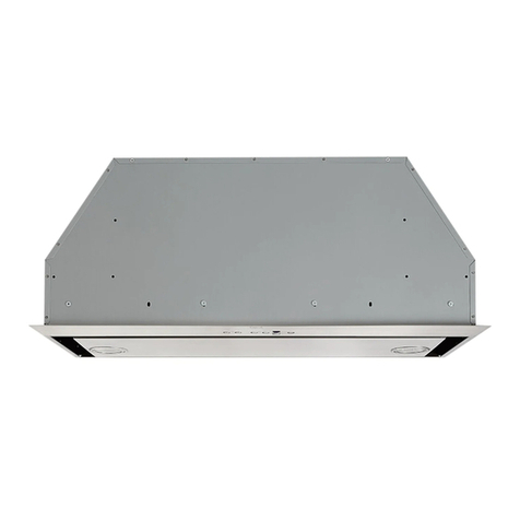
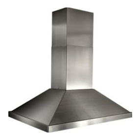
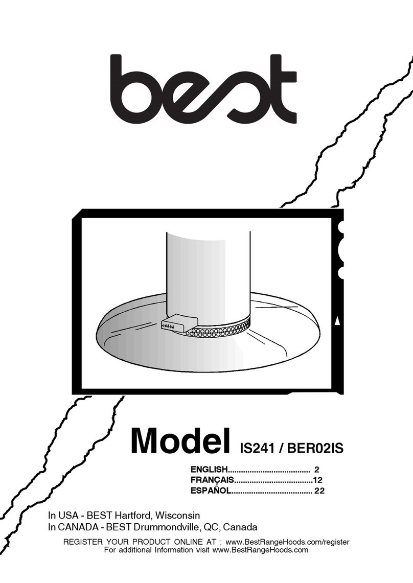
Best IS241/BER02IS User manual

- 1 -
BEST BY BROAN P.O. Box 140 Hartford, WI 53027
ENGLISH......................................3
FRANÇAIS...................................11
ESPAÑOL.................................... 19
Model IS241 / BER02IS

- 2 -

- 3 -
READ AND SAVE THESE INSTRUCTIONS
WARNING
TOREDUCETHERISKOFFIRE,ELECTRI-
CAL SHOCK, OR INJURY TO PERSONS,
OBSERVETHEFOLLOWING:
1. Usethisunitonlyin the mannerintended
by the manufacturer. If you have ques-
tions, contact the manufacturer at the
addressortelephonenumberlistedinthe
warranty.
2. Before servicing or cleaning unit, switch
power off at service panel and lock ser-
vice panel to prevent power from being
switched on accidentally. When the ser-
vice disconnecting means cannot be
locked,securelyfastenaprominentwarn-
ing device, such as a tag, to the service
panel.
3. Installationworkandelectricalwiringmust
bedonebyaqualifiedperson(s)inaccor-
dancewithallapplicablecodesandstan-
dards, including fire-rated construction
codesandstandards.
4. Sufficient air is needed for proper com-
bustionandexhaustingofgasesthrough
the flue (chimney) of fuel burning equip-
ment to prevent backdrafting. Follow the
heatingequipmentmanufacturer’sguide-
linesandsafetystandardssuch as those
publishedbytheNationalFireProtection
Association(NFPA),andtheAmericanSo-
ciety for Heating, Refrigeration and Air
ConditioningEngineers(ASHRAE),andthe
localcodeauthorities.
5. Whencuttingordrillingintowallorceiling,
donotdamageelectrical wiringandother
hiddenutilities.
6. Ductedfansmustalwaysbeventedtothe
outdoors.
7. Do not use this unit with any solid-state
speedcontroldevice.
8. To reduce the risk of fire, use only metal
ductwork.
9. Thisunitmustbegrounded.
TOREDUCETHERISKOFARANGETOP
GREASEFIRE:
A. Never leave surface units unattended at high
settings.Boiloverscausesmokingandgreasy
spilloversthatmayignite.Heatoilsslowlyonlow
ormediumsettings.
B. AlwaysturnhoodONwhencookingathighheat
orwhencookingflamingfoods.
C. Cleanventilatingfansfrequently.Greaseshould
notbeallowedtoaccumulateonfanorfilter.
D. Use proper pan size. Always use cookware
appropriateforthesizeofthesurfaceelement.
WARNING
TOREDUCETHERISKOFINJURYTOPER-
SONS IN THE EVENT OF A RANGE TOP
GREASEFIRE,OBSERVETHEFOLLOW-
ING:*
1. SMOTHERFLAMESwithaclose-fittinglid,
cookie sheet, or metal tray, then turn off
theburner. BE CAREFULTOPREVENT
BURNS.Iftheflamesdonotgooutimme-
diately,EVACUATEANDCALLTHEFIRE
DEPARTMENT.
2. NEVER PICKUPAFLAMINGPAN -You
maybeburned.
3. DONOTUSEWATER,includingwetdish-
clothsortowels-violentsteamexplosion
willresult.
4. UseanextinguisherONLYif:
A. You know you have a ClassABC ex-
tinguisherandyou already knowhow
tooperateit.
B. Thefire issmall andcontained inthe
areawhereitstarted.
C. Thefiredepartmentisbeingcalled.
D. Youcanfightthefirewithyourbackto
anexit.
*Basedon“KitchenFireSafetyTips”pub-
lishedbyNFPA.
CAUTION
1. Forgeneralventilatinguseonly.Donotuse
toexhausthazardousorexplosivemate-
rialsandvapors.
2. Toavoidmotorbearingdamageandnoisy
and/orunbalancedimpellers,keepdrywall
spray,constructiondust,etc.offpowerunit.
3. Your hood motor has a thermal overload
whichwill automaticallyshutoffthemotor
if it becomes overheated.The motor will
restart when it cools down. If the motor
continuestoshut offandrestart,havethe
hoodserviced.
4. Forbestcaptureofcookingimpurities,the
bottomofthehoodshouldbeaminimumof
24"andamaximumof30"abovethecook-
ingsurface.
5. Twoinstallersarerecommendedbecause
ofthelargesizeandweightofthishood.
6. Pleasereadspecificationlabelonproduct
forfurtherinformationandrequirements.

- 4 -
INSTALL THE DUCTWORK
NOTE: To reduce the risk of fire, use only
metal ductwork.
1.Decide where the ductwork will run between
the hood and the outside.
2. A straight, short duct run will allow the hood
to perform most efficiently.
3. Long duct runs, elbows, and transitions will
reduce the performance of the hood. Use as
few of them as possible.
4. Install a roof or wall cap. Connect 6" round
metal ductwork to cap and work back to-
wards hood location. Use duct tape to seal
the joints between ductwork sections.
INSTALL SUPPORT SYSTEM
1. Assemble the upper half of support frame to the upper plate and fix it by means of
the four supplied screws.
2. At hood location, install 2 X 4 cross framing between ceiling joists using
dimensions shown.
3. Finish the ceiling surface. Be sure to mark the location of the ceiling joists and
cross framing.
4. Fix the plate to the ceiling by means of the screws with washers and the screw
anchors.
5. Make sure screws are driven into center of
joists and framing for maximum strength.
6. Connect the lower part of the support frame
to the part previously fixed to the ceiling.
7. Adjust the overall height of the support
frame. Loosen and re-tighten the screws in
theheight adjustment slots as necessary.
Note that the hood height is 13 - 3/8” and
thatthebottomofthehoodmustbe24”min.
and 30” max. above the cooktop.
HOOD
ROOF CAP
6” ROUND
ELBOW
CROSS
FRAMING
927/32””
751/64”
TOP VIEW
OF
SUPPORT
FRAME
UPPER
PLATE
UPPER
HALF OF
SUPPORT
FRAME
6” ROUND DUCT
EAVE
VENT
DECORATIVE
FLUE
24” TO 30” ABOVE
COOKING SURFACE
CEILING
JOISTS
CROSS
FRAMING 9-27/32”
UPPER
HALF OF
SUPPORT
FRAME
HEIGHT
ADJUSTMENT
SLOTS

- 5 -
8. ATTENTION: Since the position of the lower
partofthesupportframeestablishesthefinal
position of the hood controls, turn the lower
part90°at atimebeforefinallyfixing,inorder
to obtain the required position.
Remember that in relation to the support
frame, the controls must always be in the
position indicated.
TYPICAL SUPPORT FRAME MOUNTINGS
CONNECT DECORATIVE FLUE
1. Securetheupperfluesectiontothebrackets
of the support frame with the screws
supplied.
2. Insert the lower flue section pushing it
upwards, and make it turn as far as the hole,
which has been made in the lower flue
section, is found available through its lower
opening. Partly screw one screw in the hole
and temporarily put the lower flue section
on this one. When making such operation
mind that the packing is not damaged.
LOWER
FLUE
SECTION
BRACKET
OF THE
SUPPORT
FRAME
UPPER
FLUE
SECTION

- 6 -
INSTALLATION OF GLASS
FRAME
1. Insert the transparent plastic gasket along
the edges of the glass.
2. Insert the glass, from the top to the bottom,
in the blowet unit and fix it to that one by
means of the three squares and the six
screws which have been supplied. The
squares must be fixed on the side of the
blower unit which has not got controls.
ATTENTION: Not to break the glass, it's of
much importance for the plastic gasket to
cover every part of glass frame and that the
glass is not directly in contact with metal.
Glass frame appliances are part of a
prestigious range of hand crafted cooker
hoods; due to the particular steps of
processing the glass is subjected to, the
glassbodycould present somedeffects and
distortion.
Please be very carefull not to hit the glass
with any objects made of porcelain, metal,
glass or anything else that is very heavy.
GLASS
BLOWER UNIT
PLASTIK
GASKET
METAL
BRACKETS METAL
BRACKETS
CONNECT DUCTWORK
1. Now near the hood to the lower part of the
support frame and connect the duct to the
duct collar.
2. Use 6" round metal duct to connect the
duct collar on the hood to the ductwork
above.
3. Use duct tape to make all joints secure and
air tight.
DUCT
6” DUCT
COLLAR

- 7 -
MOUNT HOOD TO SUPPORT
FRAME
1. Installthehoodtosupportframebyapposite
screws (which are bigger).
2. Fix controls to the small square inside the
lower section of decorative flue by means
of the 2 screws.
3. Fix the control box to the bearing by means
of the screws supplied. Put the cover on the
control box and fix the whole to the blower
unit by means of the screws.
4. Make electrical connections (refer to the
section “WIRING”.
5. Remove the temporary fixing screw of the
lower flue section and definitively set it in
place on the hood.
CONTROLS
WIRING
Note: This range hood must be properly
grounded. The unit should be installed by a
qualified electrician in accordance with all
applicable national and local electrical
codes.
1. Remove the wiring box cover. Remove a
knockout from the wiring box.
2. Feed 6" of power cable through the knock-
out opening and secure cable to the wiring
box with an appropriate connector.
3. Make electrical connections. Connect white
to white, black to black and green to green.
4. Replace wiring box cover and screws. Make
sure that wires are not pinched between
cover and box.
WIRING BOX
COVER

- 8 -
MAINTENANCE
Grease Filter
Cleanthegrease filter frequently.Removethe
greasefilterbypullingitdownward.Useawarm
detergent solution. Grease filters are dish-
washer safe. Note: Avoid damage to bulbs by
carefully aligning filter openings with bulbs.
Interior Hood Cleaning
DISCONNECT POWER TO HOOD BEFORE
CLEANING!
1. Remove the grease filter as shown above.
2. Remove the light bulbs. (See “HALOGEN
BULBS” on next page.
3. Remove the metal grille held in place with
four (4) screws.
4. Use a soft cloth and mild detergent solution
to wipe interior surfaces clean.
Exterior Hood Cleaning
Stainless steel is one of the easiest materials
to keep clean. Occasional care will help pre-
serve its fine appearance.
Cleaning tips:
lHot water with soap or detergent is all that
is usually needed.
lFollow all cleaning by rinsing with clear water. Wipe dry with a clean, soft cloth to
avoid water marks.
lFor discolorations or deposits that persist, use a non-scratching household
cleanser or stainless steel polishing powder with a little water and a soft cloth.
lFor stubborn cases, use a plastic scouring pad or soft bristle brush together with
cleanser and water. Rub lightly in direction of polishing lines or "grain" of the
stainless finish. Avoid using too much pressure which may mar the surface.
lDO NOT allow deposits to remain for long periods of time.
lDO NOT use ordinary steel wool or steel brushes. Small bits of steel may adhere
to the surface causing rust.
lDO NOT allow salt solutions, disinfectants, bleaches, or cleaning compounds to
remain in contact with stainless steel for extended periods. Many of these com-
pounds contain chemicals which may be harmful. Rinse with water after expo-
sure and wipe dry with a clean cloth.
Painted surfaces should be cleaned with warm water and mild detergent only.
Glass Cleaning
Use a soft cloth and a glass cleaning solution only!
DO NOT use abrasive cloths, steel wool, or scouring pads.
DO NOT use strong cleaning solutions or abrasive powders.
METAL
GRILLE
GREASE FILTER

- 9 -
OPERATION
Controls
The hood is operated using the (5) push-but-
tons located at eye-level, on the front edge of
the hood.
The light switch turns the halogen lights on
and off.
The blower on-off / speed 1 switch turns the
blower on to its lowest running speed.Turn the
bloweroffbypressingthisswitchasecondtime.
The blower speed 2 switch turns the blower on to medium-low running speed.
Pressing this switch a second time sets a timer which keeps the blower operating at
this speed for 10 minutes.
The LED will blink during this time and the blower will shut off automatically.
The blower speed 3 and blower speed 4 switches operate the same as blower
speed 2 switch except: Blower speed 3 is medium-high and blower speed 4 is high.
At the end of each working time of 30 hours, all the leds blink at the same time; this
indicates that the grease filter need to be cleaned.
Once the clean grease filter are on, push one of the three speed switches to make
the count down start again.
0-1 2 3 4
BLOWER
ON-OFF /
SPEED 1
BLOWER
SPEED 2
LIGHT
SWITCH
BLOWER
SPEED 3
LED LED LED LED
BLOWER
SPEED 4
HALOGEN BULBS
This range hood requires two halogen bulbs
(Type MR16, 12V, 20W).
ALWAYS SWITCH OFF THE ELECTRICITY
SUPPLY BEFORE CARRYING OUT ANY
OPERATIONS ON THE APPLIANCE.
To change bulbs:
1. Remove the grease filter.
2. Remove bulbs by pulling them straight downward. Do not rotate bulbs.
3. Replace bulbs by aligning the bulb’s pins with the receptacle holes and pushing
bulb upward.
IN CASE THE NEW HALOGEN BULB DOES NOT LIGHT UP ONCE IT IS ON,
CALL THE QUALIFIED PERSON.

- 10 -
WARRANTY
BROAN ONE YEAR LIMITED WARRANTY
Broan warrants to the original consumer purchaser of its products that such
products will be free from defects in materials or workmanship for a period of
one year from the date of original purchase. THEREARE NO OTHER WAR-
RANTIES, EXPRESS OR IMPLIED, INCLUDING, BUT NOT LIMITED TO,
IMPLIED WARRANTIES OR MERCHANTABILITYOR FITNESS FORAPAR-
TICULAR PURPOSE.
During this one-year period, Broan will, at its option, repair or replace, without
charge, any product or part which is found to be defective under normal use
and service.
THIS WARRANTY DOES NOT EXTEND TO FLUORESCENT LAMP START-
ERS AND TUBES. This warranty does not cover (a) normal maintenance
and service or (b) any products or parts which have been subject to misuse,
negligence, accident, improper maintenance or repair (other than by Broan),
faulty installation or installation contrary to recommended installation
instructions.
The duration of any implied warranty is limited to the one-year period as
specified for the express warranty. Some states do not allow limitation on
how long an implied warranty lasts, so the above limitation may not apply to
you.
BROAN’S OBLIGATION TO REPAIR OR REPLACE, AT BROAN’S OPTION,
SHALLBE THE PURCHASER’S SOLE AND EXCLUSIVE REMEDY UNDER
THIS WARRANTY. BROAN SHALL NOT BE LIABLE FOR INCIDENTAL,
CONSEQUENTIALOR SPECIAL DAMAGESARISING OUTOF OR IN CON-
NECTION WITH PRODUCT USE OR PERFORMANCE. Some states do not
allow the exclusion or limitation of incidental or consequential damages, so
the above limitation or exclusion may not apply to you.
This warranty gives you specific legal rights, and you may also have other
rights, which vary from state to state. This warranty supersedes all prior
warranties.
To qualify for warranty service, you must (a) notify Broan at the address
stated below or telephone: 1-800-637-1453, (b) give the model number and
part identification and (c) describe the nature of any defect in the product or
part. At the time of requesting warranty service, you must present evidence
of the original purchase date.
BEST BY BROAN, P.O. Box 140 Hartford, Wisconsin 53027

- 11 -
LISEZ ET CONSERVEZ CES INSTRUCTIONS
AVERTISSEMENTS
POUR REDUIRE LES RISQUES D’INCENDIE, DE
DECHARGESELECTRIQUESOUDEDOMMA-GES
AUX PERSONNES, OBSERVEZ LES IN-
STRUCTIONSSUIVANTES:
1. N’utilisezcetappareilquecommecelaestindiqué
par le constructeur. Si vous avez des problèmes,
contactezlefabriquantàl’adresseouaunumérode
téléphoneindiquésdanslagarantie.
2. Avantdepourvoiràl’entretienouaunettoyagede
votreappareil,éteignez-leautableaudescommandes
oubloquezletableaudescommandesafind’éviter
delemettre en marche accidentellement. Si vous
ne pouvez pas bloquer le système permettant
d’éteindrevotreappareil,appliquezunavertissement
extérieurd’unefaçonsure,commeparexempleun
panneau,surletableaudescommandes.
3. L’assemblageetlaconnexionélectriquedoiventêtre
faitspardespersonnesqualifiéesenrespectantles
normes et règlements en vigueur, y compris les
normes et règlements concernant les possibilités
d’incendie.
4. Ilestindispensablequ’ilyaitsuffisammentd’airpour
quelacombustionetl’évacuationdesgazàtravers
letuyaudubrûleurducombustibleaitlieusansretour
de flamme. Suivez les indications données par le
fabricantdubrûleurainsiquelesnormesdesécurité
comme celles qui sont publiées par l’Association
Nationale pour la Protection contre les Incendies
National Fire Protection Association (NFPA) et la
AmericanSocietyforHeating,RefrigerationandAir
ConditioningEngineers(ASHRAE),etlesautorités
localesen matière denormes.
5. Quandvouscoupezoupercezdestrousdanslemur
ou le plafond, n’abîmez pas les fils électriques ou
autres.
6. Leventilateurcanalisédoittoujoursévacuerl’airvers
l’extérieur.
7. N’utilisezpascetappareilavecunappareilcontrôlant
la vitesse à état solide.
8. Afindediminuertoutrisqued’incendien’utilisezque
des conduits en métal.
9. Votreappareildoit êtrereliéàla terre.
ATTENTION - POUR REDUIRE LES RISQUES
D’INCENDIEDESMATIERESGRASSES QUISONT
EN TRAIN DE CUIRE:
A. Ne laissez jamais ni vos éléments chauffants, ni
voscasserolesoupoêlessurlefeusanslescontrôler
sivousréglez l’apport de chaleur sur une position
élevée.Sivoscasserolesoupoêlesdébordentcela
provoque de la vapeur et des éclaboussures de
graissequipeuventprendrefeu.Chauffezleshuiles
lentement à feu bas ou moyen.
B. Faitestoujoursfonctionnervotrehotte quandvous
cuisezàdestempératuresélevéesou quandvous
cuisinez des plats flambés.
C. Nettoyezrégulièrementlesailesdevosventilateurs.
Nepermettezpasquelagraisse s’accumulesur le
ventilateur ou sur le filtre.
D. Utilisezdescasserolesdetailleappropriée.Utilisez
toujoursdesustensilesdecuissondont lataille est
appropriéeàlasurfacedevotreélémentdecuisson.
AVERTISSEMENTS
POURREDUIRELESRISQUESDEDOMMAGES
AUX PERSONNES AU CAS OÙ VOTRE CUISI-
NIERE PRENDRAIT FEU, OBSERVEZ LES
INSTRUCTIONSSUIVANTES:*
1. ETEINDRE LES FLAMMES à l’aide d’un
couvercleleplushermétiquepossible,uneplaque
àgâteaux, ouunplateau enmétal,puis éteindre
le brûleur. ATTENTION à NE PAS VOUS
BRÛLER. Si les flammes ne s’éteignent pas
immédiatement, SORTEZ ET APPELEZ LES
POMPIERS.
2. NE PRENEZ JAMAIS EN MAIN UNE POÊLE
OUUNE CASSEROLE QUIAPRISFEU -Vous
pourriezvousbrûler.
3. N’UTILISEZPASD’EAU,ni torchonsouserviettes
mouillés - vous provoqueriez une violente
explosiondevapeur.
4. Utilisez un extincteur SEULEMENT si:
A. Vous savez que vous avez un extincteur
Classe ABC, et vous en connaissez déjà le
moded’emploi.
B. Ce n’est pas un trèsgros incendie et qu’ilse
limite à l’endroi où il a explosé.
C. Vousêtes en traind’avertirlespompiers.
D. Vousavezla possibilitéd’essayerd’éteindre
l’incendie en ayant le dos tourné vers une
issue.
*D’aprèsles“SuggestionsconcernantlaSécurité
contre les incendies des cuisines” publiées par
NFPA.
ATTENTION
1. N’utilisez cet appareil que pour une ventilation
générale.Nel’utilisezpaspourévacuerdesmatières
ou des vapeurs dangereuses ou qui peuvent
exploser.
2. Pouréviterdecauserdesdommages aumoteuret
derendre les rotorsbruyantset/ou non équilibrés,
évitezquelessprays pourmurs secs,lapoussière
de construction entrent en contact avec la partie
électrique.
3. Lemoteurdevotrehotteaunthermostatquiéteindra
automatiquementlemoteurs’il est surchauffé. Le
moteur se remettra en marche lorsqu’il se sera
refroidi. Si le moteur continue à s’éteindre et à se
remettre en marche, faites vérifier votre hotte.
4. Pour mieux capturer les impuretés de cuisine, le
bas de votre hotte devrait être à une distance
minimumde24”etàunedistancemaximumde30”
au-dessusduplan de cuisson.
5. Vu que cette hotte est grande et lourde, il est
recommandédeconfierl’installationdecette hotte
àdeux personnes.
6. Nous vous recommandons de lire l’étiquette
indiquant les caractéristiques de votre hotte pour
deplusamples informations et exigences.

- 12 -
INSTALLATION DU SYSTEME
D’EVACUATION
REMARQUE: Pour réduire les risques
d’incendie,n’utilisez que des tuyaux en métal.
1. Décidez où le tuyau doit être installé, entre
votre hotte et l’extérieur.
2. Untuyaudroitetcourtpermettraàvotrehotte
de fonctionner d’une façon plus efficace.
3. Un tuyau long avec des coudes et des
transitions réduira le bon fonctionnement de
votre hotte. En utiliser le moins possible.
4. Installez un couvercle sur le toit ou au mur.
Reliez un tuyau en métal rond de 6” au
couvercle et faites-le aller jusqu’à l’empla-
cement de votre hotte. Rendez les jonctions
du tuyau hermétiques au moyen d’un ruban
pour tuyaux.
INSTALLATION DE LA STRUCTURE DE SUPPORT
1. Assembler la partie supérieure de la structure de support à la plaque supérieure
et fixez-la au moyen des quatre vis en dotation.
2. Installez, à l’emplacement de votre hotte, un cadre croisé de 2 x 4 entre les
solives du plafond en suivant les dimensions qui vous sont indiquées.
3. Perfectionnezlasurfaceduplafond.Assurez-vousde bienmarquerl’emplacement
des solives et du cadre croisé au plafond.
4. Fixer la plaque au plafond au moyen des
vis avec une rondelle et des chevilles.
5. Assurez-vous que les vis soient bien
centrées dans les solives et dans le cadre
croisé de sorte que le tout soit bien solide.
6. Assemblez la partie inférieure de la
PARTIE
SUPERIEURE DE
LA STRUCTURE
DE SUPPORT
PLAQUE
SUPERIEURE
927/32””
751/64”
9-27/32”CADRE
CROISÉ
PARTIE
SUPERIEURE
DE LA
STRUCTURE
DE SUPPORT
SOLIVES DU
PLAFOND
FISSURES
POUR
REGLAGE
EN
HAUTEUR
VUE DE
HAUT DU
CADRE
CROISÉ
CADRE
CROISÉ
DE 24” À 30” AU-DESSUS
DU PLAN DE CUISSON
TROU
D’ÉVA-
CUATION
TUYAU ROND
DE 8”
COUVERCLE
DU TOIT
COUDE ROND
DE 6”
CONDUIT
DÉCORATIF
HOTTE

- 13 -
structure de support à la partie qui a été fixée précédemment au plafond.
7. Réglez la hauteur totale de la structure de support. Désserrez et resserrez les vis
dans les fissures permettant de régler la hauteur selon ce qui est nécessaire.
Considérez que la hauteur de votre hotte est de 13 - 3/8” et que le bas de votre
hotte doit être à entre 24” et 30” au maximum au-dessus du plan de cuisson.
8. ATTENTION:lapositiondelapartieinférieuredelastructuredéterminel’orientation
finale des commandes de la hotte; avant
de la fixer définitivement vous devez donc
tourner la partie inférieure de 90 degrés à
la fois jusqu’à ce que vous obteniez la
position souhaitée. N’oubliez pas que les
commandes doivent toujours être, par
rapport à la structure, dans la position
indiquée.
ASSEMBLAGES TYPIQUES DE LA STRUCTURE DE SUPPORT
INSTALLATION DE LA
CHEMINEE TELESCOPIQUE
1. Fixer la cheminée supérieure aux étriers de
la structure de support à l'aide des vis.
2. Insérez la cheminée inférieure en la
poussant vers le haut. Faites-le tourner
jusqu’à ce que le trou, qui a été fait dans la
cheminéeinférieure,soitdisponibleàtravers
son ouverture inférieure.
Serrez partiellement une vis dans le trou et
appuyez provisoirement la cheminée
inférieur à celle-ci. En faisant ceci, faites
attention à ne pas abîmer le joint.
CHEMINEE
INFERIEURE
ETRIER DE LA
STRUCTURE DE
SUPPORT
CHEMINEE
SUPERIEURE

- 14 -
MONTAGE DE L’ELEMENT
DECORATIF EN VERRE
1. Insérez la garniture en plastique
transparente le long des bords du verre.
2. Insérez le verre, du haut en bas, dans le
group moteur et fixez-le à celui-ci au moyen
des 3 équerres et des 6 vis en dotation. Les
équerres doivent être fixées sur les côtés
du groupe moteur où il n’y a pas les
commandes.
ATTENTION: Il est important que le joint en
plastique soit bien mis en place, et que le
bord du verre n'entre pas en contact direct
avec le métal, car il risquerait de se casser.
Les hottes dotées d'un élément décoratif
en verre font partie d'une gamme d'articles
"hautde gamme"fabriquésartisanalement;
l'élément en verre peut présenter quelques
petits défauts de déformation, liés aux
traitements auxquels il a dû être soumis.
Faites très attention à ne pas heurter bru-
squement la partie en verre avec des objets
en porcelaine, métal, verre ou autres objets
lourds au risque de le casse.
BRIDE DE
JONCTION
EQUERRES
METALLIQUES
EQUERRES
METALLIQUES
VERRE GARNITURE EN
PLASTIQUE
GROUPE MOTEUR
CONNEXION DU SYSTEME
D’EVACUATION
1. Approcher maintenant la hotte à la partie
inférieure de la structure de support et
raccorder le tuyau d'évacuation de l'air à la
bride de jonction.
2. Reliez la bride de jonction au système
d’évacuation qui se trouve au-dessus au
moyen d’un tuyau rond en métal de 6”.
3. Utilisez du ruban pour tuyauterie afin de
rendre toutes les jonctions sures et étan-
ches.
TUYAU
ROND DE
6”

- 15 -
ASSEMBLAGE DE VOTRE
HOTTE A LA STRUCTURE DE
SUPPORT
1. Fixer la hotte à la structure, à l'aide des vis
(qui sont plus grandes).
2. Fixer les commandes à l’équerre qui se
trouve à l’intérieur de la cheminée inférieure
au moyen des 2 vis.
3. Fixez la boîte des commandes au support
au moyen des vis en dotation. Appuyez le
couvercle sur la boîte des commandes et
fixez le tout au groupe moteur au moyen
des vis.
4. Effectuez le raccordement électrique
(référez-vous au chapitre “INSTALLATION
ELECTRIQUE”).
5. Eliminer la vis de fixation provisoire de la
cheminée inférieure et placez celle-ci
définitivement en l’appuyant à la hotte.
COMMANDES
COUVERCLE
DE LA BOÎTE
DE CONNEXION
INSTALLATION ELECTRIQUE
Remarque:Cemodèle dehotte doitêtrerelié
à la terre correctement. Cet article devrait
être installé par un électricien qualifié selon
les lois nationales et locales en matière
d’électricité.
1. Enlevez le couvercle de la boîte de
connexion électrique. Ouvrez un trou de
la boîte de connexion électrique.
2. Faites passer un câble électrique de 6” dans
le trou et fixez le câble à la boîte de
connexion au moyen d’un connecteur
approprié.
3. Faites le raccordement électrique. Reliez le
blanc au blanc, le noir au noir et le vert au
vert.
4. Remettez le couvercle de la boîte de
connexion et les vis. Assurez-vous que les
fils se sont pas coincés entre le couvercle et
la boîte.

- 16 -
ENTRETIEN
Grille anti-graisse
Nettoyezlagrilleanti-graissefréquemment.Enlevez
lagrilleanti-graisseenlatirantverslebas.
Utilisez une solution détergente tiède. La
grille anti-graisse peut être lavée au lave-
vaisselle.
Remarque: Evitez d’abîmer les ampoules en
alignant soigneusement les ouvertures de la
grille avec les ampoules.
Nettoyage de l’intérieur de votre hotte
DEBRANCHEZ VOTRE HOTTEAVANT DE
LANETTOYER!
1. Enlevez la grille anti-graisse comme cela
est indiqué plus haut.
2. Enlevez les ampoules. (Voir “AMPOULES
HALOGENES” à la page suivante).
3. Enlevez la grille en métal en dévissant
les quatre (4) vis qui la fixent.
4. Lavez l’intérieur de votre hotte au moyen
d’un chiffon doux imprégné d’une solution
contenant un détergent neutre.
Nettoyage de l’éxterieur de votre hotte
L’acier inoxydable est une des matières les
plus faciles à nettoyer. Un entretien de temps en temps permettra de le conserver
en parfait état. Conseils pour le nettoyage:
lEau chaude et savon ou détergent est tout ce qui est normalement nécessaire.
lAprès chaque nettoyage, rincez bien à l’eau claire. Essuyez avec un chiffon
propre et doux afin d’éviter les taches d’eau.
l
Si des décolorations ou des dépôts persistent, utilisez un nettoyant domestique
non abrasif ou de la poudre pour l’acier inoxydable et un peu d’eau et un chiffon
doux.
lDans les cas difficiles, utilisez une éponge en plastique ou une brosse douce
avec du nettoyant et de l’eau. Frottez légèrement en suivant la direction du
polissage ou du “grain” de l’acier inoxydable. Evitez de frotter trop fort afin de ne
pas abîmer la surface.
lNE LAISSEZ PAS les taches trop longtemps.
lN’UTILISEZ PAS de laines d’acier ordinaires ou des brosses en acier. Des
débris d’acier pourraient adhérer à la surface et causer de la rouille.
lNE PERMETTEZ PAS que des solutions salées, des désinfectants, des
blanchissants ou des produits nettoyants restent en contact avec l’acier pendant
longtemps. Beaucoup de ces produits contiennent des produits chimiques qui
pourraient causer des dommages. Rincez à l’eau immédiatement s’ils entrent en
contact et essuyez avec un chiffon humide.
Les surfaces peintes doivent être nettoyées avec de l’eau tiède additionnée d’un
détergent doux seulement.
Nettoyage du verre
Utilisez seulement un chiffon doux et un produit nettoyant pour le verre!
N’UTILISEZ PAS d’éponges abrasives, de laine d’acier ou de produits dégraissants
N’UTILISEZ PAS de solutions nettoyantes fortes ni de poudres abrasives.
GRILLE ANTI-GRAISSE
GRILLE EN
MÉTAL

- 17 -
FONCTIONNEMENT
Commandes
Votre hotte fonctionne grâce aux (5) boutons
sur lesquels vous devez appuyer et qui se
trouvent à la hauteur de vos yeux, sur le devant
de votre hotte.
Le bouton de la lumière allume et éteint les
lampes halogènes.
Le bouton ON/OFF vitesse 1 du ventilateur
fait fonctionner le ventilateur à la vitesse la plus
basse.Vouséteignezleventilateurenappuyant
sur le bouton une deuxième fois.
Le bouton deuxième vitesse fait fonctionner le ventilateur à une vitesse
moyennement basse. En appuyant une deuxième fois sur ce bouton vous faites
fonctionner un timer qui fera fonctionner le ventilateur à cette vitesse pendant 10
minutes. Le voyant lumineux clignotera pendant tout ce temps et le ventilateur
s’arrêtera automatiquement.
Les boutons du ventilateur 3ème et 4ème vitesse font fonctionner ce dernier
comme le bouton deuxième vitesse avec la différence que le bouton 3ème vitesse
est une vitesse moyennement élevée et le bouton 4ème vitesse est une vitesse
élevée.
Auboutd'environ30heuresdefonctionnement,touslesvoyantslumineuxsemettent
à clognoter en même temps; cela indique que la grille métallique doive être nettoyée.
Après avoir remonté la grille propres, appuyer sur un des trois boutons réglant la
vitesse afin de remettre le comptage en marche.
0-1 2 3 4
LED LED LED LED
VENTILATEUR
VITESSE 4
VENTILATEUR
VITESSE 3
BOUTON DE
LA LUMIERE
VENTILATEUR
ON/OFF
VITESSE 1
VENTILATEUR
VITESSE 2
AMPOULES HALOGENES
Ce modèle de hotte a deux ampoules
halogènes (Type MR16, 12V, 20W).
AVANT DE PROCÉDER À QUELCONQUE
OPÉRATION, DÉBRANCHEZ L’APPAREIL.
Pour changer les ampoules:
1. Enlever la grille anti-graisse
2. Enlever les ampoules en les tirant tout droit
verslebas.Nepasfairetournerlesampoules.
3. Remettre les ampoules en alignant les fiches des ampoules avec les cavités à
l’intérieur desquelles elles doivent être insérées et en poussant les ampoules
vers le haut.
SI, APRÈS AVOIR REMPLACÉ LA LAMPE HALOGÈNE, CELLE-CI NE
FONCTIONNE PAS, CONTACTER LE TECHNICIEN.

- 18 -
GARANTIE BROAN LIMITÉE À UN AN
Broan garantit au consommateur-acheteur de ses produits que ces produits
seront sans défauts concernant les matières employées et concernant la
fabrication pendant une période d’un an à partir de la date d’achat. IL N’Y A
AUCUNEAUTRE GARANTIE,EXPLICITEOU IMPLICITE,YCOMPRIS, MAIS
NON PAS LIMITEE A, LES GARANTIES IMPLICITES OU CONCERNANT
LA CAPACITE COMMERCIALE OU LA CONVENANCE POUR TOUT BUT
PARTICULIER.
Pendant cette période d’un an, Broan réparera ou remplacera, s’il le jugera
nécessaire, gratuitement, tout article ou toute pièce qui résulteront défectueux
à condition qu’ils aient été utilisée et entretenu correctement.
CETTEGARANTIENES’ETENDPASAUXTUBESETAUXINTERRUPTEURS
DESLAMPESFLUORESCENTES. Cettegarantiene couvrepas (a) l’entretien
normal ni (b) tout article ou toute pièce qui aient subi une utilisation erronée,
une négligence, un accident, un entretien erroné ou une réparation (autre que
de la part de Broan), une installation défectueuse ou bien une installation ne
respectant pas les instructions d’installation recommandées.
La durée de toute garantie implicite est limitée à un an comme cela est spécifié
dans la garantie explicite. Quelques états ne permettent pas de limites quant
à la durée d’une garantie implicite, par conséquent la limitation indiquée ci-
dessus peut ne pas vous concerner.
L’OBLIGATION DE REPARER OU DEREMPLACERDE LAPARTDE BROAN
SERA LE SEUL ET EXCLUSIF REMEDE DE L’ACHETEUR COUVERT PAR
CETTE GARANTIE. BROAN NE SERA PAS RESPONSABLE DES
DOMMAGES ACCIDENTELS, CONSEQUENTIELS OU SPECIAUX DUS A
L’UTILISATION DU PRODUIT OU A SA PERFORMANCE OU EN ETANT LA
CONSEQUENCE.
Quelques états ne permettent pas l’exclusion ou la limitation des dommages
accidentels ou conséquentiels, par conséquent la limitation indiquée ci-dessus
peut ne pas vous concerner.
Cette garantie vous donne des droits légaux spécifiques, et vous pouvez aussi
avoir d’autres droits, qui varient d’Etat à Etat. Cette garantie dépasse toute
garantie précédente.
Pouravoirdroit àla garantie, vousdevez (a)avertirla MaisonBroanà l’adresse
indiquée ci-dessous ou téléphoner : 1-800-637-1453, (b) donner le numéro
du modèle et l’identification de la pièce défectueuse et (c) décrire la nature de
tout défaut de l’article ou de la pièce.Au moment où vous demandez le service
de garantie, vous devez présenter la preuve d’achat avec la date.
BEST BY BROAN, P.O. Box 140 Hartford, Wisconsin 53027
GARANTIE

- 19 -
LEA Y CONSERVE ESTAS INSTRUCCIONES
ADVERTENCIA
PARAEVITAREL RIESGO DE INCENDIO,
CORTOCIRCUITO O DAÑO PARA LAS
PERSONAS, OBSERVE ATENTAMENTE
LASSIGUIENTESNORMAS:
1. Useestaunidadsolamentedelamaneraindicada
por el fabricante; si tiene dudas, póngase en
contacto con éste a la dirección o teléfono
indicadosenlagarantía.
2. Antesdehacerunarevisiónodelimpiarlaunidad,
desconécteladelaredparaevitarqueseencienda
demaneraaccidental.Enelcasodequeésteno
puedaserdesacti-vado,seindicaráenlaplaca
decaracte-risticas.
3. Elmontajeylainstalacióneléctricadebehacerlos
untécnicoespecializadosiguiendolasnormas
estándareincluyendoaquellasdeconstrucción
antiincendio.
4. Necesita aire suficiente para una apropiada
combustiónyescapedegasesatravésdeltubo
deldepósitodequemadecombustible.Paraevitar
queelhumoaspiradovuelvaalacocina,sigalas
directivasdelfabricanteylasnormasestándar
desiguridadasícomolasnormaspublicadaspor
laAsociacióndeprevencióndeincendios(NFPA)
y la Socie-dad americana de especialistas en
cale-facción,refrigeraciónyaireacondicionadoy
ademáslasnormasdelasautoridadeslocales.
5. Haceruncorteountaladroenlaparedoenel
techo no debe dañar la instalación eléctrica u
otrasinstalacionesocultasenlapared.
6. Los conductos ventiladores deben siempre
desalojaralexterior.
7. Nouseestaunidadcondispositivodecontrolde
lavelocidadaestadosólido.
8. Paraevitarelriesgodeincendio,usesolamente
conductosdemetal.
9. Estaunidadtienequeserconectadaatierra.
PARAEVITARELRIESGODEFUEGOPOR
ALTONIVELDEGRASA:
A. Nuncaabandonelosquemadoresconelfuego
alto.Lacoccióncausahumoyrestosdegrasa
quepuedenarder.Calienteelaceiteafuego
medioobajo.
B. Enciendasiemprelacampanacuandococine
a fuego alto o cuando cocine alimentos
fácilmenteinflamables.
C. Limpieconfrecuencialosventiladores.Nose
debeacumulargrasaenelventiladoroenel
filtro.
D. Usa el tamañp de cazuela apropiado. Use
siempre utensilios de cocina de tamaño y
materialadecuados.
ADVERTENCIA
PARA EVITAR EL RIESGO DE DAÑOS A
PERSONAS EN CASO DE FUEGO POR
ALTO NÍVEL DE GRASA, TENGA EN
CUENTA LOSIGUIENTE:*
1.SOFOQUELALLAMAconunatapaderaapropiada,
unabandejametálicaó un utensiliode cocína
quepuedacubrirla,despues,apagueelquemador.
ACTÚE CON PRECAUCÍON PARA EVITAR
QUEMA-DURAS. Si la llama no se extingue
inmedia-tamente, SALGA Y LLAME A LOS
BOMBE-ROS.
2.NUNCACOJAUNASARTENENLLAMAS,porque
correelriesgodequemarse.
3.NOUSEAGUAnipañosotoallashúmidasporque
puedeprovocarseunaviolentahumareda.
4.UseunextintorSOLAMENTEsi:
A. Posee un extintor de clase ABC y sabe
perfectamentecómousarlo.
B. Elfuegoespequeñoyestácontroladoenel
mismositioenqueempezó.
C. Hallamadoconanterioridadalosbomberos.
D. Puedecombatirelfuegoretrocedíendohacia
lasalida.
*Basadoen“Seguridadantifuegoenlacocína”
publicadoporNFPA.
ADVERTENCIA
1. Sóloparaventilacióntotal.Nousegasesdeescape
peligrososomaterialesyvaporesexplosivos.
2. Paraevitardañosenelfuncionamientodelmotor
e impulsores ruidosos y/o desequi-librados,
mantengaalejadosdelaunidaddeencendido
pulverizadoresensecoopolvo.
3. Elmotortieneunniveldesobrecargatérmicaque
apagaautomáticamenteelmotorcuandoseha
recalentadoexcesivamente.Elmotorseponede
nuevoenfincionamentocuandolatemperatura
baja. Si el motor comienza a encenderse y a
apagarse,deberáhacerunarevisióndeéste.
4. Para limpiarmejorlasimpurezasalcocinar,la
parte inferior de la campana debe estar a una
temperaturamínimade24gradosymáximade
30 grados por debajo de la temperature de la
zonadecocción.
5. Debidoasugrantamañoypeso,serecomienda
su montaje por parte de dos técnicos
esperializados.
6. Serecomiendaleerlaplacadecaracte-risticas
delproductoparaulteriorinformación.

- 20 -
INSTALACION DEL TUBO DE
EXTRACCION
NOTA:para evitar elriesgo deincendio, use
solamente material de metal.
1. Decida donde va a colocar el tubo de
extracción entre la campana y la parte
exterior.
2. Unrecorridodetubocortoyrectopermitirá
a la campana funcionar de manera más
eficaz.
3. Los recorridos largos de tubo, codos y
manguitosimpidenelbuenfuncionamiento
de la campana. Use el menor número de
ellos posible.
4. Instaleunacubiertaóunatapa.Unael tubo
de metal de 6” de diámetro a la cubierta y
retrocedahastalaposicióndelacampana.Useunecintaparaprecintarlasjuntas
entre las partes del entubado.
TUBO DE 6” DE
DIÁMETRO
RESPI-
RADERO
927/32””
751/64”
9-27/32”
ENTRAMADO
PARTE
SUPERIOR
DE LA
ESTRUCTURA
DE
SOPORTE
VIGAS DEL
TECHO
RANURAS
DE AJUSTE
DE LA
ALTURA
ENTRAMADO
VISTA SUPERIOR DE
LA ESTRUCTURA DE
SOPORTE
INSTALACION DE LA ESTRUCTURA DE SOPORTE
1. Una la parte superior de la estructura de soporte a la placa superior y asegúrela
con los cuatro tornillos en dotación.
2. En el sitio donde vaya a ir la campana, instale un entramado entre las vigas del
techo utilizando las medidas dadas.
3. Termine la superficie del techo. Asegúrese de marcar la colocación de las vigas
del techo y del entramado.
4. Fije la placa al techo con los tornillos con
arandela y tacos.
5. Compruebequelostornillosvayanalcentro
de las vigas del techo para una mayor
rigidez.
6. Una la parte inferior de la estructura de
soporte con la parte anteriormente fijada
al techo.
CUBIERTA DEL TEJADO
MANGUITO
DE 6” DE
DIÁMETRO
24” A 30” POR
ENCIMA DE LA ZONA
DE COCCIÓN
CAMPANA
PARTE SUPERIOR DE
LA ESTRUCTURA DE
SOPORTE
PLACA
SUPERIOR
TUBO
DECORATIVO
Table of contents
Languages:
Other Best Ventilation Hood manuals

Best
Best WPB9 User manual

Best
Best K260A series User manual

Best
Best ISASC7388 User manual

Best
Best ICF6 User manual

Best
Best CC34ISB User manual

Best
Best WC34 Series Quick start guide

Best
Best Best KER222 Series User manual

Best
Best PIK33D User manual

Best
Best HBN1 Series Instructions for use

Best
Best DPF Series User manual
Popular Ventilation Hood manuals by other brands

KOBE
KOBE IN2636SQB-700 Installation instructions and operation manual

ELICA
ELICA HIDDEN 2.0 BLGL/A/90 Instruction on mounting and use

CAR-MON
CAR-MON TSR-P Installation and operation manual

ROBLIN
ROBLIN STRUCTURA Instructions for installation

Halton
Halton Capture Ray KVE-UV Operator's manual

Signature
Signature SHD60FLIGNE/3 Instructions for use