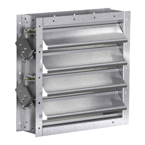
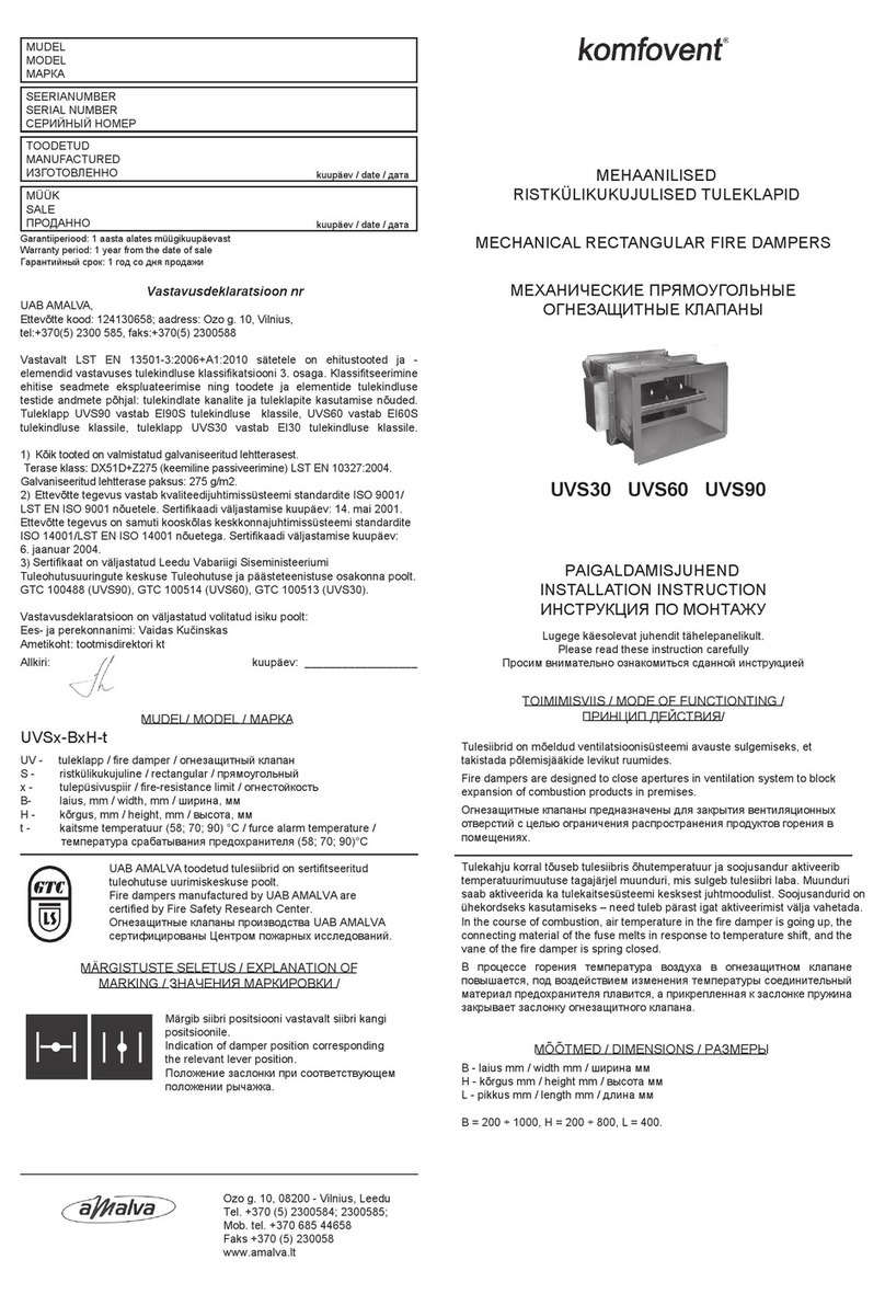
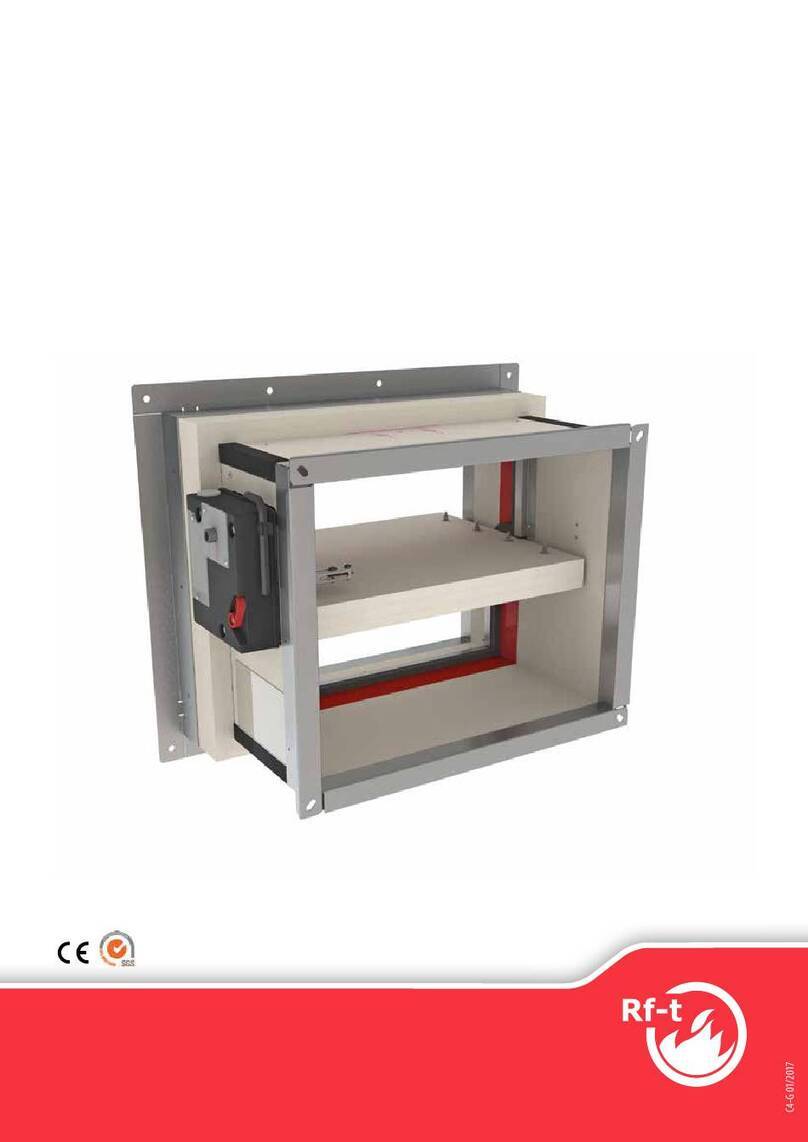
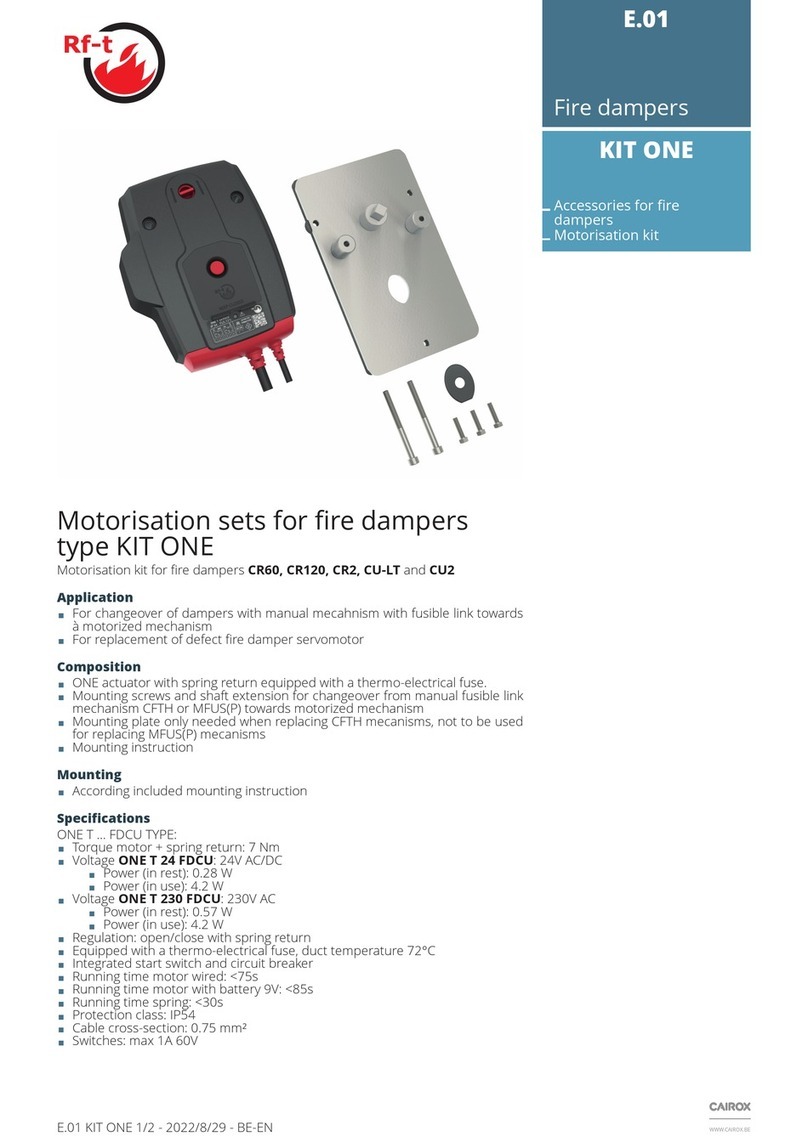
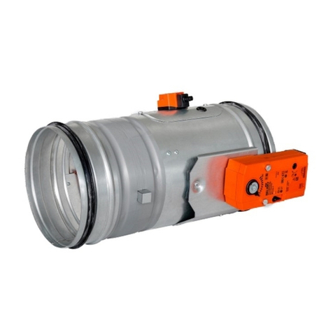
Rf-t AVANTAGE DP User manual

www.rft.be
en
Rf-Technologies nv Lange Ambachtstraat 40 9860 Oosterzele Belgium Tel +32 9 362 31 71 Fax +32 9 362 33 07 [email protected]
1812
V17-EN-E 03/2019
AVANTAGE DP
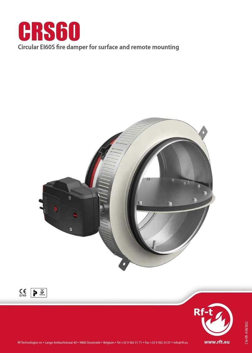
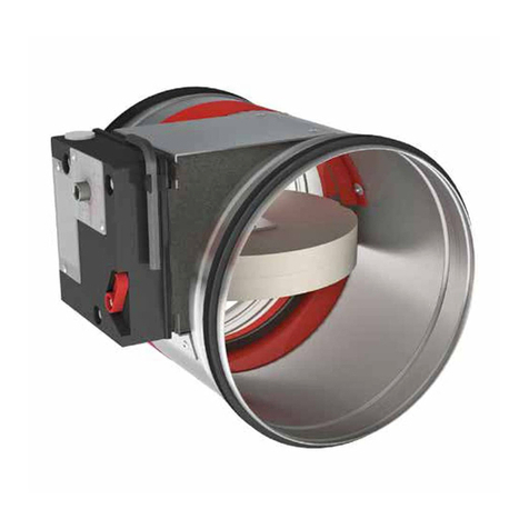
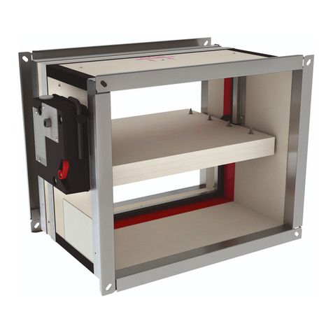
Motorised dual purpose smoke control damper.

2Table of content
Table of content
Declaration of performance 3
Product presentation AVANTAGE DP 4
Range and dimensions AVANTAGE DP 1V 4
Evolution - kits 5
Options - at the time of order 5
Storage and handling 6
Installation 6
Warning 6
Operation: manual opening 6
Operation: manual closing 7
Electrical connection 7, 16
Position in the shaft 8
Shock absorbers for the doors 9
Installation into vertical concrete shaft with built-in mounting frame 10
Installation into vertical concrete shaft (without a mounting frame) 12
Installation into vertical shaft (without a mounting frame): general instructions for all types of shafts (other than concrete) 13
Installation into vertical shaft with built-in mounting frame: general instructions for all types of shafts (other than concrete) 14
Product maintenance 15
Operation and mechanisms 16
Electrical connection 16
Weights 17
Selection graphs 18
Selection data 18
Sample order 19
Approvals and certificates 19
Explanation of the abbreviations and pictograms
Wn = nominal width
Hn = nominal height
Sn = free air passage
E = integrity
I = thermal insulation
S = smoke leakage
60/120 = fire resistance time
Pa = pascal
o -> i = meets the criteria from the outside
(o) to the inside (i)
i <-> o = fire side not important
AA = automatic activation
multi = multi compartment
1500 = pressure level 3 (1500Pa)
ved = vertical duct
hod = horizontal duct
vew = vertical wall penetration
V = volt
W = watt
V AC = Volt alternating current
V DC = Volt direct current
E.TELE = power supply magnet
E.ALIM = power supply motor
Auto = automatic
Tele = remote controlled
Pnom = nominal capacity
Pmax = maximum capacity
DAS MOD = modular product
OP = option (delivered with the product)
KIT = kit (delivered separately for repair or
upgrade)
PG = connection flange to the duct
GKB (type A) / GKF (type F): "GKB" stands
for standard plasterboards (type A accor-
ding to EN 520) while "GKF" plasterboards
offer a higher fire resistance for a similar
plate thickness (type F according to EN
520)
Cal-Sil = calcium silicate
ζ [-] = pressure loss coefficient
Q = air flow
∆P = static pressure drop
v = air speed in the duct
Lwa = A-weighted sound power level
ME = motorised
H = habitat
3
Declaration of performance
E-03/2019CE_DoP_Rf-t_V17_EN
DECLARATION OF PERFORMANCE
Declarationofperformance
CE_DoP_Rf-t_V17_EN
E-03/2019
1. Unique identication code of the product-type: AVANTAGE DP
2. Intended use/es: Smoke control damper to be used in smoke control systems, in multi-compartment applications at re temperatures, or in single-compartment applications.
3. Manufacturer: Rf-Technologies NV, Lange Ambachtstraat 40, B-9860 Oosterzele
4. System/s of AVCP: System 1
5. Harmonised standard / European Assessment Document; notied body / European Technical Assess-
ment, Technical Assessment Body, notied body; certicate of constancy of performance:
EN 12101-8:2011, Efectis with identication number 1812; Efectis_1812_CPR_1042
6. Declared performance according to EN 12101-8:2011 (re resistance according to EN 1366-10, classication according to EN 13501-4)
Essential characteristics Performance
Range Product Wall type Wall Installation Classication
350x385 mm ≤ Avantage 1V DP ≤ 700x1075 mm Avantage 60 Shaft Promatect L500 ≥ 30 mm 1 EI 60 (ved i no) S 500 C10000 AA multi
Geoam ≥ 30 mm
Geotec ≥ 30 mm
Tecniver ≥ 35 mm
Glasroc F V500 ≥ 35 mm
Exthamat ≥ 25 mm
Desenre HD ≥ 25 mm HD
Concrete ≥ 70 mm
Avantage 120 Shaft Promatect L500 ≥ 40 mm 1 EI 90 (ved i no) S 500 C10000 AA multi
Geoam ≥ 35 mm
Tecniver ≥ 45 mm
Exthamat ≥ 30 mm
Desenre ≥ 25 mm THD
Concrete ≥ 70 mm
Avantage 120 Shaft Promatect L500 ≥ 50 mm 1 EI 120 (ved i no) S 500 C10000 AA multi
Geoam ≥ 45 mm
Geoam Light ≥ 35 mm
Geotec ≥ 45 mm
Tecniver ≥ 50 mm
Glasroc F V500 ≥ 50 mm
Exthamat ≥ 35 mm
Desenre HD ≥ 35 mm HD
Desenre ≥ 45 mm
1 Type of installation: shaft-mounted 0/180°
Nominal activation conditions/sensitivity: Pass - automatic activation
Response delay (response time): closure time Pass - automatic activation
Operational reliability: cycling 10000 cycles (no load)
Durability of response delay: Pass
Durability of operational reliability: Pass
Approved accessories EASY-KAP mounting frame; motor VA DP MEC; with grill; option BLACK (700 x 1075 mm)
High operational temperature (HOT 400/30): NPD (no performance determined)
Harmonised standard
EN 12101-8:2011
The performance of the product identied above is in conformity with the set of declared performance/s.This declaration of
performance is issued, in accordance with Regulation (EU) No 305/2011, under the sole responsibility of the manufacturer identi-
ed above.
Signed for and on behalf of the manufacturer by:
Mathieu Steenland, Technical Manager
Oosterzele, 03/2019

4Product presentation AVANTAGE DP
Product presentation AVANTAGE DP
The Avantage DP is a CE marked product certified in accordance with EN12101-8, suitable for vertical mounting within apertures in
ducts or structures. Offering 60 or 120-minute fire resistance at minimum pressure loss, it is classified as suitable for multi-compart-
ment applications. In addition, Avantage DP has a C10.000 reliability classification that means it can be used in combined smoke
control and environmental systems.
Smoke evacuation shutters and dampers are suitable for use in ventilating protected lobbies, venting to shafts either naturally or
mechanically. They open to evacuate smoke in emergency situations whilst maintaining fire resistant integrity in standby position.
5simple operating tests through remote opening and resetting
5optimal free air passage and minimal pressure loss
∎tested according to EN 1366-10
∎compliant with EN 12101-8
∎approved for installation in calcium-silicate, ‘Staff’, Tecniver,
Glasroc, Extha and concrete shafts.
∎maintenance-free
∎for indoor use
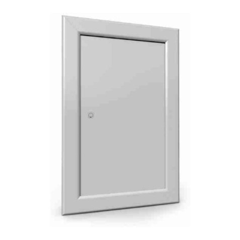
1. 1 shutter (1V)
2. aluminium frame
3. lock + key
4. blocking mechanism + automatic locking at 90°
5. product identification
6. resetting motor
4
3
6
1
2
5
AVANTAGE DP 1V
Avantage DP single shutter units (1V), with a fire-resistance of 60 minutes.
Range and dimensions AVANTAGE DP 1V60
≥
105mm
10mm
92mm
2
1
3
4
5
6
7
(1V) Wn+ 52mm
(2V) Wn/2 + 66mm
1. Refractory material
2. Sealing if mounting frame
3. Mounting frame (optional)
4. Nominal dimensions shutter Wn x Hn
5. Built-in dimensions without mounting frame (Wn+10) x (Hn+10)mm
6. Built-in dimensions with mounting frame (Wn+20) x (Hn+20)mm
7. Overall (outside) dimensions of the shutter (Wn+54) x (Hn+54)mm
≥ ≤
(Wn x Hn)
mm 350x385 700x1075

5
Evolution - kits
Evolution - kits
KITS VD24-VA Natural magnet 24 V DC
KITS FDC-VA Limit switches 'open/closed'
KITS ME AVANDP Motor DP 24V
EASY-KAP Mounting frame (delivered separately)
GFV-PB Technical front protection grill (aluminium frame and perforated plate, fastened with
screws 4.8x19mm), free air passage of 69,4%
Options - at the time of order
GFV-PB Technical front protection grill (aluminium frame and perforated plate, fastened with
screws 4.8x19mm), free air passage of 69,4%

6Storage and handling
Storage and handling
As this product is a safety element, it should be stored and handled with care.
Avoid:
• any kind of impact or damage
• contact with water
• deformation of the casing
It is recommended:
• to unload in a dry area
• not to flip or roll the product to move it
• not to use the damper as a scaffold, working table, etc.
• not to store smaller dampers inside larger ones
Installation
General points
∎The installation must comply with the installation manual delivered with the product and the classification report.
∎The installation of the shaft must comply with the classification report delivered by the shaft manufacturer.
∎Axis orientation: see the declaration of performance.
∎Avoid the obstruction of adjoining shafts.
∎Verify if the blade can move freely.
∎Rf-t smoke dampers may be applied to ducts that have been tested according to EN 1366-8 and EN 1366-9 as appropriate, con-
structed from similar materials with a fire resistance, thickness and density equal or superior to these of the tested materials.
Caution: when fitting, the product should be handled with care and remain protected from any sealing products.
Caution: before putting the installation into operation, clean off all the dust and dirt.
Caution: bear in mind the blade's clearance inside the smoke evacuation duct.
Warning
Extreme care must be taken in the installation of smoke control dampers and regard should be given to health and safety provisions.
The installation should only be carried out by suitably trained and qualified personnel. Installers, users and maintainers are remin-
ded of their duties under the U.K. Health and Safety at Work Act, the European Community Workplace Directives and other National
Legislation and Guidelines on Safety.
Do not attempt to lift, support or move the damper by the drive linkage transom. If the transom is bent in any way it will cause dama-
ge to the motor drive shaft and gearbox. Do not attempt to operate the damper if the transom bar is damaged.
Operation: manual opening
20°
1. Unlocking 1V
Turn the key 20° anti clockwise and the damper will push open
without releasing the magnetic latch. Turn the key past 20
degrees and the latch will disengage and the damper will also
push open. To re-arm the latch insert key and turn clockwise.
1

7
Installation
Operation: manual closing
20°
1. Resetting 1V
Insert the key and turn 20° clockwise. Press the drive linkage
bar to release from the stand-open position and pull the dam-
per door slowly closed until the latch locates with the strike
plate.
Electrical connection
The DP drive motor is a 24 volt DC 0.8 amp rated motor that requires a 24 volt ± 5% fully smooth and rectified supply. The damper
operates on a 2 wire reverse polarity connection. Terminate cables in a site supplied junction box with screw terminals. The 24 volt
DC motor connections are polarity sensitive. Be sure positive (+) and Negative (-) are connected correctly.
Wire colours: brown = 24 V DC (+); blue = 24 V DC (-); white = not used (programming).
Operation: brown + and blue -: opening; brown - and blue +: closing.
It is recommended that only control systems conforming to standards ISO 21927-9, pr EN12101-9 and EN 12101-10 are used to operate
the smoke control dampers.
1. The shutter is a 24 volt DC drive open, drive closed unit incor-
porating a 24 volt DC pulse active locking latch. It is supplied
with double insulated trailing lead cables for onsite connection
in accordance with these instructions. Mechanisms need to be
visually inspected prior to installation to check any physical
damage to actuators or cables.
The trailing lead cable exit position can be any of the 4 corners
of the damper.
2. Drill a hole in the refractory material at the chosen corner(s).
The galvanised part at the inside of the shutter is already
indented.
Caution: after passing and fixing the cables, it is necessary to
caulk around the electrical cables with fire resistant adhesive
sealant (BCM f.e.).
1
1 2

8Installation
1
1
2
3. It is recommended that once the holes have been drilled at
the cable exit position, the cables are laid and clipped in posi-
tion around the inside perimeter of the damper framing and
each cable “Fed and Drawn” through these holes to the outside
of the damper spigot. At all times take care not to damage the
cable insulation.
Lead the cables through the opening. Use the fixation clips
(1) and the plastic cable clamp (2) to attach the cables to the
frame.
Position in the shaft
≥105≥105 ≥105
1. Smoke control dampers should be fitted to the smoke
evacuation shaft and / or fire resisting duct with a penetration
seal of a type used in the test of the damper to EN1366-10. They
may be installed within the duct or wall thickness of the fire
separating element or onto the surface of these elements or to
a fire resisting branch duct connecting to the shaft.
≥ 105 mm
≥ 105 mm
≥ 105 mm
≥ 70 mm
≥ 70 mm
≥ 70 mm
3
1 2
3 4

9
Installation
Shock absorbers for the doors
1. Shock absorbers (foam) come standard with the shutter. They
can be affixed to the inner face of the door to prevent it from
hitting the shaft wall when opening.
2. Be sure to cut these blocks to the correct dimensions so that
the blocking mechanism can engage when the door opens.
1 2

10 Installation
Installation into vertical concrete shaft with built-in mounting frame
The product was tested and approved in:
Product Range Wall type Classication
Avantage 60 350x385 mm ≤ Avantage 1V DP ≤ 700x1075 mm Shaft Concrete ≥ 70 mm EI 60 (ved i no) S 500 C10000 AA multi
Avantage 120 350x385 mm ≤ Avantage 1V DP ≤ 700x1075 mm Shaft Concrete ≥ 70 mm EI 90 (ved i no) S 500 C10000 AA multi
AVANTAGE DP
EASY-KAP
A=20-100 mm
A=20 mm
(W+A) x (H+A) mm
Mortar
1. In case of sealing the mounting frame:
Make an opening with dimensions (W+20) x (H+20) mm till
(W+100) x (H+100) mm.
In case of screwing of the mounting frame:
Make an opening with dimensions (W+20) x (H+20) mm.
2. The mounting frame should always be fastened to the
concrete shaft with screws and dowels (Ø6 x minimum 60 mm,
steel or stainless steel).
For an opening with dimensions up to (W+20) x (H+20) mm:
Two sealing lugs are provided at the bottom and at the top of
the mounting frame: fold these against the shaft and fasten the
mounting frame to the lining with 4 screws Ø6 x 60 mm, taking
care not to misshape it. These screws can be inserted through
any of the punched holes in the lugs, depending on the thick-
ness of the shaft wall.
The finished opening must be the same size as the mounting
frame (W+10) x (H+10) mm.
For an opening with dimensions up to (W+100) x (H+100) mm:
Apply mortar around the opening to reduce the opening to
the outer dimensions of the frame, then proceed as mentioned
above to fasten the frame to the opening. Make sure that the
gap between the frame and the opening in sealed completely
with mortar.
The mortar must harden completely before the damper is
fastened to the mounting frame.
1 2

11
Installation
3. Set aside the screws that are affixed to one of the cross slats,
then unscrew the 4 cross slats of the mounting frame and fold
the 8 plates in the frame.
4. Rotate the four fastening plates on the damper 90° (to the
upright position).
5. Open and position the shutter in the mounting frame. If VM
magnet: remove the key from the lock to open the shutter.
Fasten the shutter onto the mounting frame with the 4 screws
supplied with the mounting frame, as shown in the drawing.
Tightening the screws pulls the shutter towards the wall until
its final position.
It also makes it possible to slightly correct the angle of the
shutter with respect to the mounting frame.
Connect the mechanism according to the wiring diagram.
Check the mobility of the shutter.
3 4
5

12 Installation
Installation into vertical concrete shaft (without a mounting frame)
The product was tested and approved in:
Product Range Wall type Classication
Avantage 60 350x385 mm ≤ Avantage 1V DP ≤ 700x1075 mm Shaft Concrete ≥ 70 mm EI 60 (ved i no) S 500 C10000 AA multi
Avantage 120 350x385 mm ≤ Avantage 1V DP ≤ 700x1075 mm Shaft Concrete ≥ 70 mm EI 90 (ved i no) S 500 C10000 AA multi
1. Rotate the four fastening plates on the damper 90° (to the
upright position).
The fastening plates are not used for an installation without a
mounting frame.
AVANTAGE DP
(Wn+10) x (Hn+10) mm
2. Make an opening with dimensions (W+10) x (H+10) mm.
Open and position the shutter in the opening. If VM magnet:
remove the key from the lock to open the shutter.
Fix the shutter in the opening using 4 screws and dowels Ø6 x
40 mm.
Connect the mechanism according to the wiring diagram.
Check the mobility of the shutter.
1 2

13
Installation
Installation into vertical shaft (without a mounting frame): general instructions for all types of shafts (other than concrete)
The product was tested and approved in:
Product Range Wall type Classication
Avantage 60 350x385 mm ≤ Avantage 1V DP ≤ 700x1075 mm Shaft Promatect L500 ≥ 30 mm EI 60 (ved i no) S 500 C10000 AA multi
Avantage 60 350x385 mm ≤ Avantage 1V DP ≤ 700x1075 mm Shaft Geoam ≥ 30 mm EI 60 (ved i no) S 500 C10000 AA multi
Avantage 60 350x385 mm ≤ Avantage 1V DP ≤ 700x1075 mm Shaft Geotec ≥ 30 mm EI 60 (ved i no) S 500 C10000 AA multi
Avantage 60 350x385 mm ≤ Avantage 1V DP ≤ 700x1075 mm Shaft Tecniver ≥ 35 mm EI 60 (ved i no) S 500 C10000 AA multi
Avantage 60 350x385 mm ≤ Avantage 1V DP ≤ 700x1075 mm Shaft Glasroc F V500 ≥ 35 mm EI 60 (ved i no) S 500 C10000 AA multi
Avantage 60 350x385 mm ≤ Avantage 1V DP ≤ 700x1075 mm Shaft Exthamat ≥ 25 mm EI 60 (ved i no) S 500 C10000 AA multi
Avantage 60 350x385 mm ≤ Avantage 1V DP ≤ 700x1075 mm Shaft Desenre HD ≥ 25 mm HD EI 60 (ved i no) S 500 C10000 AA multi
Avantage 120 350x385 mm ≤ Avantage 1V DP ≤ 700x1075 mm Shaft Promatect L500 ≥ 40 mm EI 90 (ved i no) S 500 C10000 AA multi
Avantage 120 350x385 mm ≤ Avantage 1V DP ≤ 700x1075 mm Shaft Geoam ≥ 35 mm EI 90 (ved i no) S 500 C10000 AA multi
Avantage 120 350x385 mm ≤ Avantage 1V DP ≤ 700x1075 mm Shaft Tecniver ≥ 45 mm EI 90 (ved i no) S 500 C10000 AA multi
Avantage 120 350x385 mm ≤ Avantage 1V DP ≤ 700x1075 mm Shaft Exthamat ≥ 30 mm EI 90 (ved i no) S 500 C10000 AA multi
Avantage 120 350x385 mm ≤ Avantage 1V DP ≤ 700x1075 mm Shaft Desenre ≥ 25 mm THD EI 90 (ved i no) S 500 C10000 AA multi
Avantage 120 350x385 mm ≤ Avantage 1V DP ≤ 700x1075 mm Shaft Promatect L500 ≥ 50 mm EI 120 (ved i no) S 500 C10000 AA multi
Avantage 120 350x385 mm ≤ Avantage 1V DP ≤ 700x1075 mm Shaft Geoam ≥ 45 mm EI 120 (ved i no) S 500 C10000 AA multi
Avantage 120 350x385 mm ≤ Avantage 1V DP ≤ 700x1075 mm Shaft Geoam Light ≥ 35 mm EI 120 (ved i no) S 500 C10000 AA multi
Avantage 120 350x385 mm ≤ Avantage 1V DP ≤ 700x1075 mm Shaft Geotec ≥ 45 mm EI 120 (ved i no) S 500 C10000 AA multi
Avantage 120 350x385 mm ≤ Avantage 1V DP ≤ 700x1075 mm Shaft Exthamat ≥ 35 mm EI 120 (ved i no) S 500 C10000 AA multi
Avantage 120 350x385 mm ≤ Avantage 1V DP ≤ 700x1075 mm Shaft Tecniver ≥ 50 mm EI 120 (ved i no) S 500 C10000 AA multi
Avantage 120 350x385 mm ≤ Avantage 1V DP ≤ 700x1075 mm Shaft Glasroc F V500 ≥ 50 mm EI 120 (ved i no) S 500 C10000 AA multi
Avantage 120 350x385 mm ≤ Avantage 1V DP ≤ 700x1075 mm Shaft Desenre HD ≥ 35 mm HD EI 120 (ved i no) S 500 C10000 AA multi
Avantage 120 350x385 mm ≤ Avantage 1V DP ≤ 700x1075 mm Shaft Desenre ≥ 45 mm EI 120 (ved i no) S 500 C10000 AA multi
1. Rotate the four fastening plates on the damper 90° (to the
upright position).
The fastening plates are not used for an installation without a
mounting frame.
AVANTAGE DP
e
≥ 105 mm
e
A = 2 x e + 10 mm
(W+A) x (H+A) mm
(W+10) x (H+10) mm
2. Make an opening with dimensions (W+A) x (H+A) mm.
A = 2 x thickness sleeve (e) + 10 mm.
Fit a sleeve of the same type and thickness of the duct (thick-
ness e) of minimum 105 mm deep in the opening.
Fix the sleeve to the shaft wall.
With the opening prepared the shutter can be handled into po-
sition, from the room side. Ensure that the trailing lead cables
are not trapped at this stage and freely hang loose. Do not dis-
tort or twist the frames as this will affect the correct operation
and sealing of the shutter. Check for squareness by measuring
the frame diagonals (they must measure the same).
Fix the shutter in the opening using 4 screws and dowels Ø6 x 40 mm.
Caution: make sure that the screws don't exceed the sleeve's
thickness!
Connect the mechanism according to the wiring diagram.
Check the mobility of the shutter.
Caution: before putting the installation into operation, clean
off all the dust and dirt.
1 2

14 Installation
Installation into vertical shaft with built-in mounting frame: general instructions for all types of shafts (other than concrete)
The product was tested and approved in:
Product Range Wall type Classication
Avantage 60 350x385 mm ≤ Avantage 1V DP ≤ 700x1075 mm Shaft Promatect L500 ≥ 30 mm EI 60 (ved i no) S 500 C10000 AA multi
Avantage 60 350x385 mm ≤ Avantage 1V DP ≤ 700x1075 mm Shaft Geoam ≥ 30 mm EI 60 (ved i no) S 500 C10000 AA multi
Avantage 60 350x385 mm ≤ Avantage 1V DP ≤ 700x1075 mm Shaft Geotec ≥ 30 mm EI 60 (ved i no) S 500 C10000 AA multi
Avantage 60 350x385 mm ≤ Avantage 1V DP ≤ 700x1075 mm Shaft Tecniver ≥ 35 mm EI 60 (ved i no) S 500 C10000 AA multi
Avantage 60 350x385 mm ≤ Avantage 1V DP ≤ 700x1075 mm Shaft Glasroc F V500 ≥ 35 mm EI 60 (ved i no) S 500 C10000 AA multi
Avantage 60 350x385 mm ≤ Avantage 1V DP ≤ 700x1075 mm Shaft Exthamat ≥ 25 mm EI 60 (ved i no) S 500 C10000 AA multi
Avantage 60 350x385 mm ≤ Avantage 1V DP ≤ 700x1075 mm Shaft Desenre HD ≥ 25 mm HD EI 60 (ved i no) S 500 C10000 AA multi
Avantage 120 350x385 mm ≤ Avantage 1V DP ≤ 700x1075 mm Shaft Promatect L500 ≥ 40 mm EI 90 (ved i no) S 500 C10000 AA multi
Avantage 120 350x385 mm ≤ Avantage 1V DP ≤ 700x1075 mm Shaft Geoam ≥ 35 mm EI 90 (ved i no) S 500 C10000 AA multi
Avantage 120 350x385 mm ≤ Avantage 1V DP ≤ 700x1075 mm Shaft Tecniver ≥ 45 mm EI 90 (ved i no) S 500 C10000 AA multi
Avantage 120 350x385 mm ≤ Avantage 1V DP ≤ 700x1075 mm Shaft Exthamat ≥ 30 mm EI 90 (ved i no) S 500 C10000 AA multi
Avantage 120 350x385 mm ≤ Avantage 1V DP ≤ 700x1075 mm Shaft Desenre ≥ 25 mm THD EI 90 (ved i no) S 500 C10000 AA multi
Avantage 120 350x385 mm ≤ Avantage 1V DP ≤ 700x1075 mm Shaft Promatect L500 ≥ 50 mm EI 120 (ved i no) S 500 C10000 AA multi
Avantage 120 350x385 mm ≤ Avantage 1V DP ≤ 700x1075 mm Shaft Geoam ≥ 45 mm EI 120 (ved i no) S 500 C10000 AA multi
Avantage 120 350x385 mm ≤ Avantage 1V DP ≤ 700x1075 mm Shaft Geoam Light ≥ 35 mm EI 120 (ved i no) S 500 C10000 AA multi
Avantage 120 350x385 mm ≤ Avantage 1V DP ≤ 700x1075 mm Shaft Geotec ≥ 45 mm EI 120 (ved i no) S 500 C10000 AA multi
Avantage 120 350x385 mm ≤ Avantage 1V DP ≤ 700x1075 mm Shaft Exthamat ≥ 35 mm EI 120 (ved i no) S 500 C10000 AA multi
Avantage 120 350x385 mm ≤ Avantage 1V DP ≤ 700x1075 mm Shaft Tecniver ≥ 50 mm EI 120 (ved i no) S 500 C10000 AA multi
Avantage 120 350x385 mm ≤ Avantage 1V DP ≤ 700x1075 mm Shaft Glasroc F V500 ≥ 50 mm EI 120 (ved i no) S 500 C10000 AA multi
Avantage 120 350x385 mm ≤ Avantage 1V DP ≤ 700x1075 mm Shaft Desenre HD ≥ 35 mm HD EI 120 (ved i no) S 500 C10000 AA multi
Avantage 120 350x385 mm ≤ Avantage 1V DP ≤ 700x1075 mm Shaft Desenre ≥ 45 mm EI 120 (ved i no) S 500 C10000 AA multi
AVANTAGE DP
e
≥ 105 mm
e
A = 2 x e + 10 mm
(W+A) x (H+A) mm
(W+10) x (H+10) mm
1. Make an opening with dimensions (W+A) x (H+A) mm.
A = 2 x thickness sleeve (e) + 20 mm.
Fit a sleeve of the same type and thickness of the duct (thick-
ness e) of minimum 105 mm deep in the opening.
Fix the sleeve to the shaft wall.
2. Two sealing lugs are provided at the bottom and at the top of
the mounting frame: fold these against the sleeve.
In case of fixing by screws, fasten the mounting frame to the
sleeve with chipboard screws (Ø 6 x e) mm. These screws can
be fixed in one of the openings provided for this purpose,
depending on the depth of the sleeve.
Take care not to misshape the frame during its installation. The
finished opening must be the same size as the mounting frame
(W+10) x (H+10) mm.
1 2

15
Installation
3. Set aside the screws that are affixed to one of the cross slats,
then unscrew the 4 cross slats of the mounting frame and fold
the 8 plates in the frame.
4. Rotate the four fastening plates on the damper 90° (to the
upright position).
5. With the opening prepared the shutter can be handled
into position, from the room side. Ensure that the trailing lead
cables are not trapped at this stage and freely hang loose. Do
not distort or twist the frames as this will affect the correct
operation and sealing of the shutter. Check for squareness by
measuring the frame diagonals (they must measure the same).
Fasten the shutter onto the mounting frame with the 4 screws sup-
plied with the mounting frame, as shown in the drawing. Tightening
the screws pulls the shutter towards the wall until its final position.
It also makes it possible to slightly correct the angle of the
shutter with respect to the mounting frame.
Caution: make sure that the screws don’t exceed the sleeve’s
thickness!
Connect the mechanism according to the wiring diagram.
Check the mobility of the shutter.
Caution: before putting the installation into operation, clean
off all the dust and dirt.
Product maintenance
Smoke control dampers must form part of a professionally designed Smoke and Heat Exhaust Ventilation System (SHEVS) that will
be specially suited to an individual buildings size, usage and structure. SHEVS are Fire Safety Installations and it is essential they are
subject to the routine inspection and maintenance requirements of the country of installation of the SHEV system. For example,
BS7346 part 8, NF S 61-933 and EN 13306. Avantage and Kamouflage DP dampers are virtually maintenance free, however, they will
require occasional operation and maintenance as part of a system specific routine operational test and maintenance procedure. It
is recommended that as part of the system testing and maintenance procedure that different individual dampers are operated at
each system test such that each damper within a system is inspected, checked and tested at least once in any 6-month period. The
following instructions are a general guide and our recommendations to the procedures required: a) Operate each ventilator at least
once; checking that the unit opens and closes fully. b) Visually observe the control mechanisms ensuring the devices are in place and
are not obviously damaged or obstructed. c) Inspect each ventilator in its open position to check that the intumescent fire seals and
smoke seals between the vent frame and doors are not damaged and are securely attached. Wipe any dirt build up from the seals.
Inspect the door leading and trailing edge seals and lightly lubricate with a machine oil and a silicone grease to the release latch.
Maintenance
∎No specific maintenance required.
∎Schedule at least two running checks each year.
∎Remove dust and all other particles before start-up.
∎Follow the local maintenance regulations (i.e. BS9999 Annex V; NF S 61-933) and EN13306.
3 4
5

16 Operation and mechanisms
Operation and mechanisms
Operation: general points
∎See under 'Installation' (manual opening and closing).
Caution : please note dampers must be fully open before starting supply and/or extract fans.
VA DP MEC Mechanism for motorised unlocking and resetting.
Mechanism for the motorised unlocking and resetting of the Smoke Control Damper Avantage DP, Kamouflage DP.
1. Motor and housing
2. Motor mounting bracket
3. Drive arm guide pin
4. Motor drive arm
5. Cable connectors
4
2
1
3
5
Unlocking
∎manual unlocking: manual release with the damper key (delivered in the bag together with the installation guidelines)
∎remote unlocking: remote by connection of 24 V DC
Resetting
∎manual resetting: rearm magnetic latch with key (delivered in the bag together with the installation guidelines), press the drive
linkage arm to unlock position and pull the damper closed
∎motorised resetting: remote resetting by inverting the voltage connection
Electrical connection
VA DP MEC
DC FC
M
DC
FC
M
DC
FC
M
DC
FC
DC : Switch closed position smoke evacuation shutter
FC : Switch open position smoke evacuation shutter
black
grey
blue
black
grey
blue
brown
blue
24VDC
24VDC
24VDC
MEC Nominal voltage
motor
Nominal voltage
magnet
Power consumption
(stand-by)
Power consumption
(operating) Standard switches Protection class
VA DP MEC 24 V DC N/A N/A Pnom 15VA 1mA...6A, DC 5V...AC 250V IP 32

17
Weights
Weights
AVANTAGE DP 1V60 - 1V120
Hn\Wn [mm] 350 400 450 500 550 600 650 700
385 kg 7,9 8,3 8,8 9,2 9,7 10,3 11,0 11,6
415 kg 8,3 8,8 9,4 9,9 10,4 11,0 11,5 12,0
445 kg 8,6 9,2 9,7 10,3 10,8 11,4 11,9 12,5
475 kg 8,9 9,5 10,0 10,6 11,2 11,8 12,3 12,9
505 kg 9,2 9,8 10,4 11,0 11,5 12,1 12,7 13,3
535 kg 9,4 10,1 10,7 11,3 11,9 12,5 13,1 13,8
565 kg 9,7 10,3 11,0 11,6 12,3 12,9 13,5 14,2
595 kg 10,0 10,6 11,3 11,9 12,6 13,3 13,9 14,6
625 kg 10,4 11,0 11,6 12,2 12,9 13,6 14,3 15,0
655 kg 10,7 11,3 11,9 12,5 13,3 14,0 14,7 15,4
685 kg 10,9 11,5 12,1 12,8 13,6 14,3 15,1 15,8
715 kg 11,2 11,8 12,4 13,1 13,9 14,7 15,4 16,2
745 kg 11,4 12,1 12,7 13,4 14,2 15,0 15,8 16,6
775 kg 11,6 12,3 13,0 13,7 14,6 15,4 16,2 17,0
805 kg 11,9 12,6 13,3 13,9 14,9 15,7 16,6 17,4
835 kg 12,1 12,8 13,6 14,2 15,2 16,1 17,0 17,8
865 kg 12,4 13,1 13,8 14,5 15,5 16,4 17,3 18,2
895 kg 12,6 13,4 14,1 14,8 15,9 16,8 17,7 18,6
925 kg 12,9 13,6 14,4 15,1 16,2 17,2 18,1 19,0
955 kg 13,1 13,9 14,7 15,4 16,5 17,5 18,5 19,5
985 kg 13,4 14,2 15,0 15,7 16,9 17,9 18,9 19,9
1015 kg 13,6 14,4 15,3 16,0 17,2 18,2 19,3 20,3
1045 kg 13,9 14,7 15,5 16,2 17,5 18,6 19,6 20,7
1075 kg 14,1 15,0 15,8 16,5 17,8 18,9 20,0 21,1

18 Selection data
Selection data
AVANTAGE DP 1V60 - 1V120
Hn\Wn [mm] 350 400 450 500 550 600 650 700
385 ζ [-] 2,522 2,079 1,768 1,540 1,365 1,227 1,114 1,021
415 ζ [-] 2,263 1,869 1,592 1,388 1,231 1,107 1,006 0,923
445 ζ [-] 2,053 1,698 1,448 1,264 1,122 1,009 0,918 0,842
475 ζ [-] 1,879 1,556 1,328 1,160 1,031 0,927 0,844 0,774
505 ζ [-] 1,732 1,437 1,227 1,073 0,953 0,858 0,781 0,717
535 ζ [-] 1,607 1,334 1,141 0,998 0,887 0,799 0,727 0,667
565 ζ [-] 1,500 1,246 1,066 0,933 0,829 0,747 0,680 0,625
595 ζ [-] 1,406 1,169 1,001 0,876 0,779 0,702 0,639 0,587
625 ζ [-] 1,323 1,101 0,943 0,826 0,735 0,662 0,603 0,554
655 ζ [-] 1,250 1,041 0,892 0,781 0,695 0,627 0,571 0,524
685 ζ [-] 1,185 0,987 0,846 0,741 0,660 0,595 0,542 0,498
715 ζ [-] 1,126 0,938 0,805 0,705 0,628 0,566 0,516 0,474
745 ζ [-] 1,073 0,895 0,767 0,673 0,599 0,540 0,492 0,452
775 ζ [-] 1,025 0,855 0,733 0,643 0,573 0,517 0,471 0,433
805 ζ [-] 0,981 0,818 0,703 0,616 0,549 0,495 0,451 0,415
835 ζ [-] 0,941 0,785 0,674 0,591 0,527 0,475 0,433 0,398
865 ζ [-] 0,904 0,755 0,648 0,568 0,507 0,457 0,417 0,383
895 ζ [-] 0,870 0,726 0,624 0,547 0,488 0,440 0,401 0,369
925 ζ [-] 0,838 0,700 0,602 0,528 0,470 0,425 0,387 0,356
955 ζ [-] 0,809 0,676 0,581 0,510 0,454 0,410 0,374 0,344
985 ζ [-] 0,782 0,653 0,562 0,493 0,439 0,397 0,362 0,332
1015 ζ [-] 0,757 0,632 0,544 0,477 0,425 0,384 0,350 0,322
1045 ζ [-] 0,733 0,613 0,527 0,462 0,412 0,372 0,339 0,312
1075 ζ [-] 0,711 0,594 0,511 0,448 0,400 0,361 0,329 0,303
AVANTAGE DP 1V60 - 1V120 - Free air passage (m²)
Hn\Wn [mm] 350 400 450 500 550 600 650 700
385 Sn [m²] 0,1090 0,1270 0,1450 0,1630 0,1810 0,1990 0,2170 0,2350
415 Sn [m²] 0,1190 0,1380 0,1580 0,1770 0,1960 0,2160 0,2350 0,2550
445 Sn [m²] 0,1280 0,1490 0,1700 0,1910 0,2120 0,2330 0,2540 0,2750
475 Sn [m²] 0,1380 0,1610 0,1830 0,2050 0,2280 0,2500 0,2730 0,2950
505 Sn [m²] 0,1480 0,1720 0,1960 0,2200 0,2440 0,2680 0,2920 0,3150
535 Sn [m²] 0,1580 0,1830 0,2080 0,2340 0,2590 0,2850 0,3100 0,3360
565 Sn [m²] 0,1670 0,1940 0,2210 0,2480 0,2750 0,3020 0,3290 0,3560
595 Sn [m²] 0,1770 0,2050 0,2340 0,2620 0,2910 0,3190 0,3480 0,3760
625 Sn [m²] 0,1870 0,2170 0,2470 0,2770 0,3070 0,3360 0,3660 0,3960
655 Sn [m²] 0,1960 0,2280 0,2590 0,2910 0,3220 0,3540 0,3850 0,4170
685 Sn [m²] 0,2060 0,2390 0,2720 0,3050 0,3380 0,3710 0,4040 0,4370
715 Sn [m²] 0,2160 0,2500 0,2850 0,3190 0,3540 0,3880 0,4230 0,4570
745 Sn [m²] 0,2260 0,2620 0,2980 0,3330 0,3690 0,4050 0,4410 0,4770
775 Sn [m²] 0,2350 0,2730 0,3100 0,3480 0,3850 0,4230 0,4600 0,4970
805 Sn [m²] 0,2450 0,2840 0,3230 0,3620 0,4010 0,4400 0,4790 0,5180
835 Sn [m²] 0,2550 0,2950 0,3360 0,3760 0,4170 0,4570 0,4970 0,5380
865 Sn [m²] 0,2640 0,3060 0,3480 0,3900 0,4320 0,4740 0,5160 0,5580
895 Sn [m²] 0,2740 0,3180 0,3610 0,4050 0,4480 0,4910 0,5350 0,5780
925 Sn [m²] 0,2840 0,3290 0,3740 0,4190 0,4640 0,5090 0,5540 0,5990
955 Sn [m²] 0,2940 0,3400 0,3870 0,4330 0,4790 0,5260 0,5720 0,6190
985 Sn [m²] 0,3030 0,3510 0,3990 0,4470 0,4950 0,5430 0,5910 0,6390
1015 Sn [m²] 0,3130 0,3630 0,4120 0,4610 0,5110 0,5600 0,6100 0,6590
1045 Sn [m²] 0,3230 0,3740 0,4250 0,4760 0,5270 0,5780 0,6290 0,6790
1075 Sn [m²] 0,3330 0,3850 0,4370 0,4900 0,5420 0,5950 0,6470 0,7000

19
Sample order
Sample order
AVANTAGE DP 1V 120 400 685 VD24
52 3 4 61
1. product
2. 1 shutter (1V)
3. fire resistance of 60 or 120 minutes
4. width
5. height
6. option: type magnet and voltage
Approvals and certicates
All our products are submitted to a number of tests by official test institutes. Reports of these tests form the basis for the approvals of
the products.
1812
Efectis_1812_CPR_1042
If the product is manipulated in any other way than described in this manual, Rf-Technologies will decline any responsibility and the guarantee will expire!
Table of contents
Other Rf-t Fire And Smoke Damper manuals