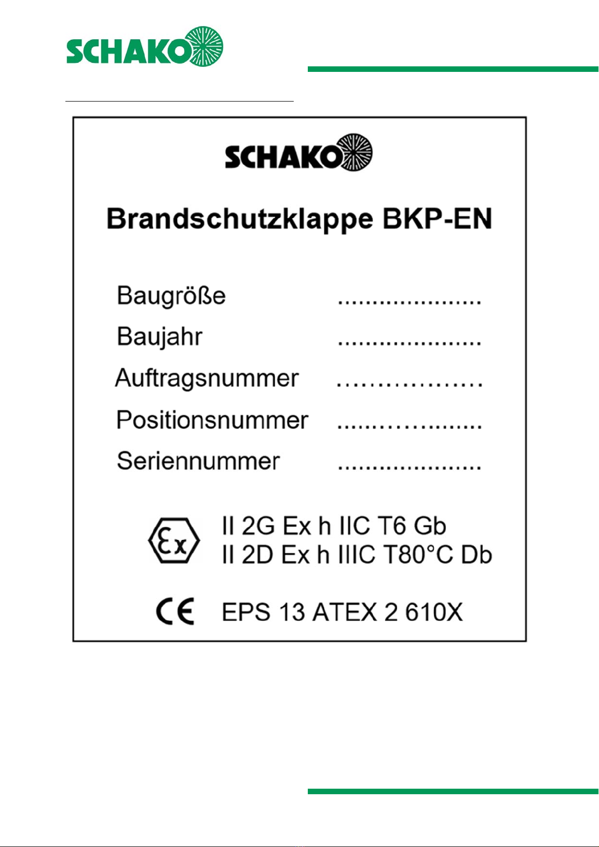
Fire damper BKP-EN
Additional operating instructions according to ATEX 2014/34/EU
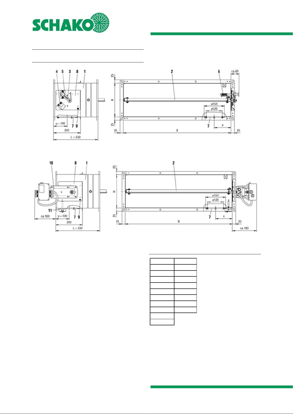
Models and dimensions
Construction subject to change
No return possible Version: 2020-09-01 | Page 8
Improper transport/handling may result in damage/func-
tional impairment. In addition to that, the film of the
transport packaging must be removed and the delivery in-
spected for completeness.
In storage, fire dampers must be protected from dust,
dirt, moisture and the effects of temperature (e.g. direct
sunlight, heat-emitting light source, etc.). They must not
be exposed to direct effects of the weather and must not
be stored below -20 °C or above 50 °C.
The fire damper must be protected from dirt and damage.
After installation is complete, any dirt must be removed
immediately.
Enough space must be provided for installation, mortar
lining, etc.
Carry out a functional check of the fire damper before and
after mounting and ensure ready access.
Electrical installations or work on electrical components
may only be carried out by skilled electricians. The supply
voltage must be switched off when performing this work
and secured against being switched on again.
We would like to point out that only suitable cleaning ma-
terials may be used for cleaning fire dampers in stainless
steel design!
Information regarding assembly and commissioning
Prior to being installed in the ventilation system, the fire
damper must be checked for damage. Damaged fire dampers
must not be installed.
The device may only be used in accordance with its desig-
nated use in air ventilation systems for supply air and return
air.
Use only approved fastening material for mounting.
No additional parts may be
fastened to the fire damper.
The fire damper must be connected to the ventilation duct
network on both sides in electrically conducting fashion.
In order to avoid the risk of static charges, the fire damper
must be connected to the on-site equipotential bonding on
the grounding connection provided for this purpose.
Make sure that the ventilation systems are not subjected to
any anomalous operating conditions, such as vibrations, pres-
sure surges or high proportions of solids in the medium.
Information regarding functional check and inspec-
tion
Proper functional check increases operational safety and the
service life of the device. This is why the devices should be
subjected to regular inspection.
If inspection dates are prescribed by law, they must be com-
plied with.
The operating personnel must be informed, prior to starting
functional check and inspection work.
The personal safety measures must be looked up in the safety
data sheet. Hazard caused by contact or inhaling hazardous
substances must be excluded by taking appropriate safety
measures.
Prior to functional check or inspection, all system components
up- and downstream of the device must be switched off and
secured against being switched on again.
The following inspection criteria must be observed:
Visual inspection of the device
Check the fastening of the device
Check the electrical connections
Check the grounding connection for tight fit and good
contact
Functional control
For additional inspections, please refer to the technical
documentation or additional instructions for functional
check
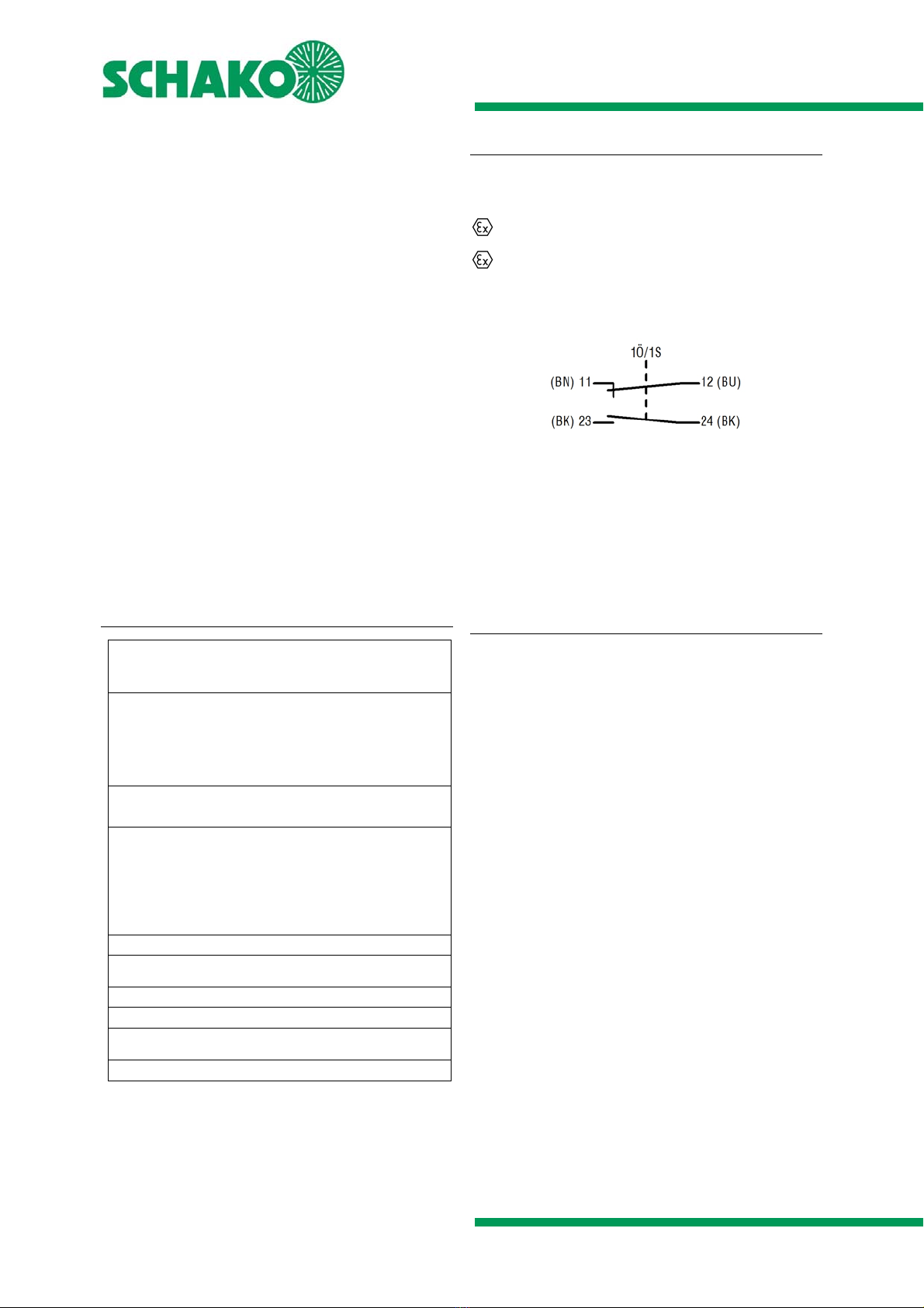
Use and electrical connection of actuators in areas
subject to explosion hazards
Only ATEX-approved electrical equipment according to ATEX
Directive 2014/34/EU for the zones 1, 2, 21, 22, such as actu-
ators, terminal boxes and thermocouples according to our
specifications may be used for SCHAKO KG devices.
The connection lines must be installed for permanent use and
in such a way that they are sufficiently protected from me-
chanical and thermal damage.
Devices with explosion-protected actuators and terminal
boxes have to be attached over the external potential con-
necting terminal to the potential equalisation provided by the
customer with at least 4 mm² cooper solid-core.
The electrical connection lines of the actuators
must be connected in a terminal box according to ATEX Di-
rective 2014/34/EU for the zones 1, 2, 21, 22, if the electrical
connection is made in an explosive area.
The dimensioning of the conductor cross-sections must be ob-
served.
The actuators are maintenance-free with respect to their
function, but the test specifications according to ATEX direc-
tives
or factory regulations must be observed.