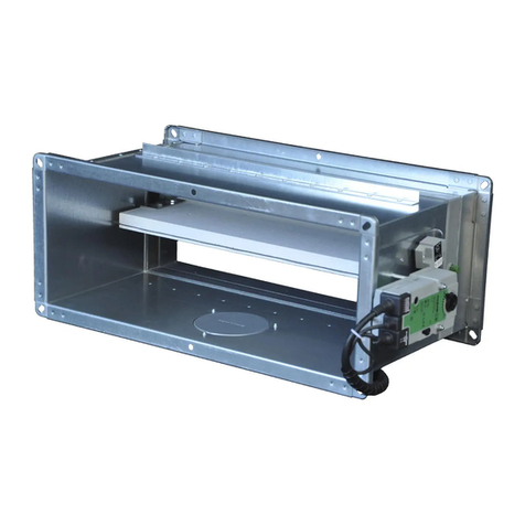
Bevent Rasch FENIX4 Installation and operation manual

www.bevent-rasch.com
FIRE SAFETY
22/01/2021
FENIX4 /
FENIX+
Monitoring system
Commissioning instruction

2BORÅS Tel +46 (0)33 - 23 67 80 STOCKHOLM Tel +46 (0)8 - 54 55 12 70
Contents
General ........................................................................................................... 2
Products ........................................................................................................ 3
1. Installation .................................................................................................. 3
2. Connection ................................................................................................. 4
3. Commissioning ........................................................................................... 6
Functions ........................................................................................................ 9
Management and service .............................................................................. 10
General
The FENIX4 master control unit and FENIX+ slave unit contain electronic com-
ponents that may be damaged in the event of improper use. When connecting
dampers, smoke detectors and other connections, the unit must be powered
down!
The cover to access the terminal blocks is removed by unscrewing the cover
on the lower part of the control unit. The connection terminals for 230 V AC are
opened by inserting a screwdriver with a suitable width into the notch above the
connector and then bend the screwdriver slightly upwards.
FENIX4 Monitoring system – Commissioning instruction

3BORÅS Tel +46 (0)33 - 23 67 80 STOCKHOLM Tel +46 (0)8 - 54 55 12 70
FENIX4 Monitoring system – Commissioning instruction
Products
System structure
FENIX4 master
FENIX4 is the device with the interactive touch display.
FENIX4 supports between 1-4 dampers and smoke detector circuits, which
are automatically detected during commissioning. FENIX4 is used either inde-
pendently for monitoring 1-4 dampers and smoke detector circuits or together
with slave units FENIX+ for up to 16 dampers and smoke detector circuits.
FENIX+ slave unit
FENIX+ works as an additional module for the possibility to connect an addi-
tional 1-4 dampers and smoke detector circuits to the system. The FENIX+
slave unit is automatically identified by FENIX4 and connected dampers and
smoke detector circuits are automatically shown as usual on the display of
FENIX4. FENIX+ is addressed easily with a physical knob, see the connection
instructions for more information.
FENIX 0-10 V module
When using regulating fire dampers, regulation can be performed in two
different ways, either via a local 0-10 V signal out at the damper or via master
communication (Modbus TCP or BACnet IP). If local control is desired with
0-10V, the FENIX 0-10 V module is used to separate the local control signal,
from, e.g. a room sensor, and the 10 V signal from FENIX that takes over during
a functional test to check that the dampers can open.
20Nov.
09:38
NÄTVERK
INSTÄLLNINGAR
NATTDRIFT
Funktionstest pågår
Funktionstestarspjäll 3 och 4 av 8
Återståendetid
5 min 48 sek
OK
FENIX (Master)
Smoke detectors
(Up to 4)
Smoke detectors
(Up to 4)
Smoke detectors
(Up to 4)
Smoke detectors
(Up to 4)
Fire dampers
(Up to 4)
Fire dampers
(Up to 4)
Fire dampers
(Up to 4)
Fire dampers
(Up to 4)
FENIX+ (Slave 1) FENIX+ (Slave 2) FENIX+ (Slave 3)
1. Installation
Install FENIX4 and FENIX+ with the requisite fasteners. A wall mount frame
is fitted on the units at the factory and should be used to maintain the IP65
enclosure class.
The FENIX 0-10 V module is mounted on a wall or cable ladder. Power supply
cables and end position indication from the damper motor are connected
directly to the damper module. This in turn, is connected to FENIX4 master or
FENIX+ slave unit.

4BORÅS Tel +46 (0)33 - 23 67 80 STOCKHOLM Tel +46 (0)8 - 54 55 12 70
FENIX4 Monitoring system – Commissioning instruction
2. Connection
Connect dampers, smoke detectors and other connections according to the
following connection instructions when the unit is powered down.
NOTE! If a smoke detector is not connected, then noterminating resistance
should be fitted.
The connection instructions for the ON/OFF damper (open/closed) are different
from the regulating 0-10V damper, see the connection instructions.
4 6 7 8 9 10
DET1
DAMPER/
DAMPER 3
DAMPER/
DAMPER 4
532
FUNC.
TEST
33 34
EXT.
ALARM
35 36
NIGHT
MODE
37
S2
S6
G0
G
0-10 V
11 13 14 15 16 17
DET2
12
S2
S6
G0
G
0-10 V
18 20 21 22 23 24
DET3
19
S2
S6
G0
G
0-10 V
25 27 28 29 30 31
DET4 INPUTS
38
SUM.
ALARM
DET. SERV.
ALARM
39 40 41 42 44 45
EXT.
STOP
N
N
A
A
B
B
43
OUTPUTS
26
S2
S6
G0
G
C
46 47 48
NC
NO
C
C
NC
NO
NO
0-10 V
X
ON/OFF damper *)
X
2641
5123 5
X
3
5211
4
6
2
3
FENIX 0-10 V
0-10 V damper *)
Example 0-10 V damper with
local control signal 1-10 V and
FENIX 0-10 V module
Example common
ON/OFF damper
XX
0-10 V damper *)
X
2641
55
1233
Example 0-10 V damper
with control via
Modbus/BACnet
FENIX+
slave unit
XX
DAMPER/
DAMPER 1
DAMPER/
DAMPER 2
123
230 VAC
100 VA
50 Hz 3
6
1
***) For
channel
detector
RCKD
**) At room
detector
RCRD
COM
FENIX4
FENIX+ slavenhet
Cable recommendations
ON/OFF dampers, e.g. BSKC6 = EKKR/ELQRB/EQQRB 4x1 mm2
Regulating damper 0-10 V, e.g. BSKC6R = EKKR/ELQRB/EQQRB 5x1 mm2(7x1 mm2)
Between FENIX4 and FENIX+ slave units: UTP cable AWG22, AWG24 with 2 pairs.
A, , B, N must be connected (one conductor will be over).
Recommended max. length between FENIX4 master and FENIX+ slave unit: 300 m.
For local 0-10 V
control from, for
example room
sensors, the FENIX
0-10 V module
is used.
S2 S6 G0 G
XX
FENIX4/FENIX+
0-10 V
S2 S6 G0 G0
G
0-10 V 0-10 V
S6
S2 S4
1
-S1
0-10 V
2
+
FENIX 0-10 V
35
X
External 0-10 V signal
from room sensors,
for example
0-10 V damper *)
***) For duct detector RCKD
connected in series
**) For room detector RCRD
connected in series
*) 24 V DC max. 10 VA
When separate thermal
sensor is used, connect
in series with motor.
Thermal
sensor
Actuator
36 1
36 1
***) For duct detector RCKD
connected in series
**) For room detector RCRD
connected in series
*) 24 V DC max. 10 VA
When separate thermal
sensor is used, connect
in series with motor.
Thermal
sensor
Actuator
36 1
36 1
***) For duct detector RCKD
connected in series
**) For room detector RCRD
connected in series
*) 24 V DC max. 10 VA
When separate thermal
sensor is used, connect
in series with motor.
Thermal
sensor
Actuator
36 1
36 1
NAB
46 47 48
EFX communication line
Screen & ”N” connection optional
4 6 7 8 9 10
DET1
DAMPER/
DAMPER 3
DAMPER/
DAMPER 4
5
S2
S6
G0
G
0-10 V
11 13 14 15 16 17
DET2
12
S2
S6
G0
G
0-10 V
18 20 21 22 23 24
DET3
19
S2
S6
G0
G
0-10 V
25 27 28 29 30 31
DET4
N
N
A
A
B
B
26
S2
S6
G0
G
46 47 48
0-10 V
X
ON/OFF damper *)
X
2641
5123 5
X
3
5211
4
6
2
3
FENIX 0-10 V
0-10 V damper *)
Example 0-10 V
Example ON/OFF
Connections
in RCHD
Connections
in RCHD
Connections in
RCHD
Connections in
RCKD
XX
DAMPER/
DAMPER 1
DAMPER/
DAMPER 2
123
SLAVE
ADDRESS
31
2
230 VAC 100 VA 50 Hz
12
Overtemperature detector RCHD
together with smoke detector
12
12
12345
FENIX+
slave unit
FENIX+ slave unit
or FENIX4
COM
4 6 7 8 9 10
DET1
DAMPER/
DAMPER 3
DAMPER/
DAMPER 4
5
S2
S6
G0
G
0-10 V
11 13 14 15 16 17
DET2
12
S2
S6
G0
G
0-10 V
18 20 21 22 23 24
DET3
19
S2
S6
G0
G
0-10 V
25 27 28 29 30 31
DET4
N
N
A
A
B
B
26
S2
S6
G0
G
46 47 48
0-10 V
X
ON/OFF damper *)
X
2641
5123 5
X
3
5211
4
6
2
3
FENIX 0-10 V
0-10 V damper *)
Example 0-10 V
Example ON/OFF
Connections
in RCHD
Connections
in RCHD
Connections in
RCHD
Connections in
RCKD
XX
DAMPER/
DAMPER 1
DAMPER/
DAMPER 2
123
SLAVE ADDRESS
31
2
230 VAC 100 VA 50 Hz
12
Overtemperature detector RCHD
together with smoke detector
12
12
12345
FENIX+
slave unit
FENIX+ slave unit
or FENIX4
COM

5BORÅS Tel +46 (0)33 - 23 67 80 STOCKHOLM Tel +46 (0)8 - 54 55 12 70
FENIX4 Monitoring system – Commissioning instruction
For local 0-10 V
control from, for
example room
sensors, the FENIX
0-10 V module
is used.
Connection terminals Function Description
4+5, 11+12, 18+19,
25+26
Connection of smoke detector
circuits
Each smoke detector circuit should have a 2.2 kOhm's resistance mounted at the
end of the circuit, see the wiring diagram. The terminating resistance of 2.2 kOhm is
connected to the last detector in each circuit. If a central fire alarm and/or no smoke
detectors are used, a resistance of 2.2 kOhm should not be installed on these terminals.
Max 24 V DC 90 mA.
6-10, 13-17, 20-24,
27-31
Connection of fire damper For standard ON/OFF dampers, the input is not used for 10 V, this is done only for regu-
lating dampers, see wiring diagrams.
The damper output on G and G0 is 24 V DC, max 10 VA per output.
Note! Only 1 fire damper per output!
Inputs Function Description
32+33 External function test/resetting
External alarm
In the event of a short circuit, the controller performs a functional test and may reset the
external incoming alarm, provided that terminals 34+35 do not have an open circuit.
These terminals cannot be jumpered for automatic resetting. Instead, see options under
settings.
34+35 External incoming alarm In the event of an open circuit between terminals, External incoming alarm is activated,
jumpered on delivery and if External incoming alarm is not used.
36+37 Night mode In the event of short circuiting of the terminals, the panel enters Night mode whereby
all dampers close without the controller generating alarms. Used, for example, during
intermittent operation. Night mode can also be a good safety measure for preventing the
spread of combustion gases when the ventilation is switched off, duct-mounted smoke
detectors do not have the same opportunity to detect smoke when no air is transported
in the system.
Outputs Function Description
38+39+40 Main alarm Potential-free changeover contact that switches for:
• Detector failure • Damper failure • Tripped detector • External incoming alarm
• Power outage • System failure • Communication failure with slave units
• Internal battery needs to be replaced
In normal operation, terminals 38+40 have contact.
Drawn in de-energised/alarm mode.
Max 24 V AC/DC, 3 A
41+42+43 Service alarm detector circuits Potential-free changeover contact that switches for soiled detector.
In normal operation, terminals 41+43 have contact.
Drawn in de-energised/alarm mode.
Max 24 V AC/DC, 3 A
44+45 External stop of fan/
unit
Breaking potential-free contact that breaks for:
• Functional testing of fire dampers • Main alarm
In normal operation, terminals 44+45 have contact.
Drawn in de-energised/alarm mode.
Max 24 V AC/DC, 3 A
46+47+48 Bus contact, communication
between FENIX and FENIX+
Communication cable between FENIX and FENIX+ is connected here.
44+45 External stop of fan/
unit
Breaking potential-free contact that breaks for:
• Functional testing of fire dampers • Main alarm
In normal operation, terminals 44+45 have contact.
Max 24 V AC/DC, 3 A
Network connection Cable connection RJ45, 10Base-T/100Base-TX auto-negotiation
Cable length Max. 100 m
Cabling Min. Cat 5
SLAVE
ADDRESS
31
2
Addressing slave units Addressing knob for slave unit (FENIX+ only). Connected slave units shall be addressed
in the order: 1, 2, 3. Turn the knob to change the address.
Indication of communication
between master unit FENIX
and slave unit FENIX+
Green LED on
Red LED on
Orange flashing 1 time/sec
Voltage on, everything OK
Battery problems FENIX4
No contact between FENIX+ and FENIX4
2. Connection cont.
• Measure the voltage with a
multimeter use a well-known
brand.
• Check cables using an
Ohmmeter with all devices
disconnected.
• Never use a megohmmeter! • The connection and discon-
nection of all cables are made
with FENIX4 master and
FENIX+ slave unit powered
down.

6BORÅS Tel +46 (0)33 - 23 67 80 STOCKHOLM Tel +46 (0)8 - 54 55 12 70
FENIX4 Monitoring system – Commissioning instruction
3. Commissioning
1. Make sure that connected slave units are addressed in the order 1, 2, 3
according to the addressing knob at the far right of the FENIX+ slave unit as
shown below. If no FENIX+ slave unit is used, you can ignore this point.
2. Power the units with 230V AC.
3. Press START on the display and follow the commissioning instructions below.
The start page when powered up.
FENIX+ slavenhet
NAB
46 47 48
EFX communication line
Screen & ”N” connection optional
4 6 7 8 9 10
DET1
DAMPER/
DAMPER 3
DAMPER/
DAMPER 4
5
S2
S6
G0
G
0-10 V
11 13 14 15 16 17
DET2
12
S2
S6
G0
G
0-10 V
18 20 21 22 23 24
DET3
19
S2
S6
G0
G
0-10 V
25 27 28 29 30 31
DET4
N
N
A
A
B
B
26
S2
S6
G0
G
46 47 48
0-10 V
X
ON/OFF damper *)
X
2641
5123 5
X
3
5211
4
6
2
3
FENIX 0-10 V
0-10 V damper *)
Example 0-10 V
Example ON/OFF
Connections
in RCHD
Connections
in RCHD
Connections in
RCHD
Connections in
RCKD
XX
DAMPER/
DAMPER 1
DAMPER/
DAMPER 2
123
SLAVE
ADDRESS
31
2
230 VAC 100 VA 50 Hz
12
Overtemperature detector RCHD
together with smoke detector
12
12
12345
FENIX+
slave unit
FENIX+ slave unit
or FENIX4
COM

7BORÅS Tel +46 (0)33 - 23 67 80 STOCKHOLM Tel +46 (0)8 - 54 55 12 70
FENIX4 Monitoring system – Commissioning instruction
Make sure that the number of FENIX+ slave units
found matches your installation.
If the number of units is not correct, use the trouble-
shooting guide on the display.
If a fire damper is connected incorrectly or does not
work, a red icon will appear.
For safety reasons, a faulty system cannot be start-
ed. Use the troubleshooting guide on the display to
correct the fault before commissioning.
Check that the number of fire dampers and smoke
detector circuits found match the installation.
Use the troubleshooting guide on the display if
your dampers or smoke detector circuits are not
displayed.
NB: The icons also show whether the dampers are of
ON/OFF type or regulating 0-10V.
Example system with 1 FENIX+ slave unit.
Example system with 1 smoke detector circuit and 8 fire dampers with a faulty
or broken damper.
Example system with 1 smoke detector circuit and 8 fire dampers.

8BORÅS Tel +46 (0)33 - 23 67 80 STOCKHOLM Tel +46 (0)8 - 54 55 12 70
FENIX4 Monitoring system – Commissioning instruction
After an approved functional test has been carried
out, FENIX is part of the fire protection.
Example system with 1 smoke detector circuit and 8 fire dampers after correct
commissioning.
Symbol descriptions
“DAMPER 1”
Indicates which
damper on the unit
FENIX4 / FENIX+
Closed
damper
“0-10 V”
Indicates whether the
damper is regulating:
0-10 V = regulating
No box = On/Off
Damper
in middle
position
“SLAVE 1”
Indicates which slave
unit the damper
belongs to.
Open damper
DAMPER 1
DAMPER 1
AMPER
AMPER
SLAVE 1
DAMPER 1
AMPER
AMPER
CIRCUIT 1
CIRCUIT 1
RCUI
IRCUIT
RCUIT
C
CIRCUIT 1
SLAVE 1
DAMPER 1
DAMPER 1
AMPER
AMPER
SLAVE 1
DAMPER 1
AMPER
AMPER
CIRCUIT 1
CIRCUIT 1
RCUI
IRCUIT
RCUIT
C
CIRCUIT 1
SLAVE 1
DAMPER 1
DAMPER 1
AMPER
AMPER
SLAVE 1
DAMPER 1
AMPER
AMPER
CIRCUIT 1
CIRCUIT 1
RCUI
IRCUIT
RCUIT
C
CIRCUIT 1
SLAVE 1
DAMPER 1
DAMPER 1
AMPER
AMPER
SLAVE 1
DAMPER 1
AMPER
AMPER
CIRCUIT 1
CIRCUIT 1
RCUI
IRCUIT
RCUIT
CCIRCUIT 1
SLAVE 1
"CIRCUIT 1"
Indicates which
detector circuit
on the unit
FENIX4 / FENIX+
“SLAVE 1”
Indicates which
slave unit the detec-
tor circuit belongs to.
DAMPER 1
DAMPER 1
AMPER
AMPER
SLAVE 1
DAMPER 1
AMPER
AMPER
CIRCUIT 1
CIRCUIT 1
RCUI
IRCUIT
RCUIT
C
CIRCUIT 1
SLAVE 1
DAMPER 1
DAMPER 1
AMPER
AMPER
SLAVE 1
DAMPER 1
AMPER
AMPER
CIRCUIT 1
CIRCUIT 1
RCUI
IRCUIT
RCUIT
C
CIRCUIT 1
SLAVE 1
Green
= All OK
Yellow
= Service
Red
= Error / Alarm
CIRCUIT 1 CIRCUIT 1 CIRCUIT 1

9BORÅS Tel +46 (0)33 - 23 67 80 STOCKHOLM Tel +46 (0)8 - 54 55 12 70
FENIX4 Monitoring system – Commissioning instruction
Function description
Functions and settings via the display
Date and Time
The date and time are set from the factory, but can be eas-
ily changed on-site if necessary. The unit is equipped with
automatic summer and winter time adjustment.
Language
Easily choose between Swedish and English.
Zone dampers and smoke detector circuits
The dampers and smoke detector circuits can easily be
divided into up to four zones. The zones then serve as their
own fire compartments and the smoke detector circuits
can close one or more zones. This is a function that can
be used, for example, for tenant adaptations where the
entire system should not shut down on each local smoke
detector circuit.
Default setting: all smoke detectors and fire dampers
belong to zone 1.
Time of functional testing
Easily set the interval when functional testing of the fire
dampers is performed and when during the day to do it.
Selectable ranges:
• 1 time every 24 hours
• 1 time every 48 hours
(recommended and default setting on delivery) • 1
time per week
• 1 time per month
• 1 time every 6 months
Perform functional testing
If necessary, you can easily perform a functional test via
the display on FENIX4. Can also be performed by shorting
terminals 32 and 33.
Device information and communication settings
Simply set the desired communication settings for Modbus
TCP or BACnet IP via the display.
IP address is assigned automatically via Dynamic Host Con-
figuration Protocol (DHCP). If a fixed IP address is desired,
this can be configured via the settings in the touch display.
Delay External stop
If desired, functional testing of fire dampers can be delayed
by 5 minutes. Relay “EXT. STOP” between terminals 44
and 45 then breaks directly for internal functional testing,
the functional test of the dampers is performed first after a
5 minute delay, which then allows the electric heating coils
to cool down.
Default setting: no delay.
Automatic reset of External incoming alarm
Normally an External incoming alarm (34 + 35) needs to be
acknowledged on the unit via the display or terminal block
32 + 33 (default setting), this function permits External
incoming alarms to be acknowledged automatically when
a possible external alarm stops. Default setting: no auto-
matic reset.
System reset
The system is easily reset to the default settings when
necessary.
Automatic functions integrated in FENIX
Dynamic troubleshooting diagrams
Instead of the traditional troubleshooting documents that
previously accompanied older controllers, FENIX shows
exactly what fault occurred and proposed actions directly
on the display, such as if a damper does not make contact
with the limit switch for the closed position:
The unit then shows exactly what damper fault has been
identified, the possible slave unit FENIX+ that the damper
belongs to and which connection terminals and cables
should be checked and troubleshot. This function facili-
tates any service and troubleshooting in the event of a fault
during the lifespan of the property. The same pedagogical
approach applies to smoke detector circuits, external
alarms and other functions that trigger something in the
controller.
Dynamic trouble shooting diagrams and associated action
texts play an important role in the simplicity of FENIX.
Automatic functional testing
All connected fire dampers are automatically functionally
tested. In order to ensure that regulating dampers work
at all damper angles, check the limit switches for both the
open and closed positions for all connected dampers.
Automatic shutdown of the entire system in the event
of alarms in two different zones
As a safety measure, all connected fire dampers are closed
if two smoke detectors from different zones alarm at the
same time. This is because it can then be assumed that
the fire has spread between the fire compartments and
that the entire system should be closed.

10 BORÅS Tel +46 (0)33 - 23 67 80 STOCKHOLM Tel +46 (0)8 - 54 55 12 70
FENIX4 Monitoring system – Commissioning instruction
Management and service
The FENIX system is designed to facilitate management and service by present-
ing troubleshooting suggestions and measures for each specific service issue.
This means that you do not have to keep any troubleshooting manuals and other
documentation.
The unit will alert when the internal battery needs to be replaced. This can also be
done in connection with service or an obligatory ventilation control (OVK).
Instructions for replacing the battery
1. Power down the unit, no 230V AC must be connected when replacing the
battery.
2. Remove the cover by loosening the screws as shown below.
3. Replace the CR2032 battery on the right side of the PCB.
Replace the battery within 10 seconds to prevent the unit from losing
its settings. If the unit is left without a battery connected for more than
10seconds, any settings must be made again.
4. Refit the front by screwing on the cover again.
5. The unit automatically restarts with retained settings.
20 Nov.
09:38
N
Ä
TVERK
Ä
Ä
INSTÄLLNINGAR
N
A
TTDRIFT
A
A
OK

11BORÅS Tel +46 (0)33 - 23 67 80 STOCKHOLM Tel +46 (0)8 - 54 55 12 70
FENIX4 Monitoring system – Commissioning instruction

190703.0002_ENG / January 2021 teamfront.se
www.bevent-rasch.com
This manual suits for next models
1
Table of contents
Other Bevent Rasch Fire And Smoke Damper manuals