SW-Stahl und Werkzeugvertriebs GmbH Tel. +49 (0) 2191 / 46438-0
F56essartSresukreveL ax +49 (0) 2191 / 46438-40
ed.lhatsws@ofni:liaM-EdiehcsmeR79824-D
Instruction Manual
BGS technic KG
Bandwirkerstr. 3
42929 Wermelskirchen
Tel.: 02196 720480
Fax.: 02196 7204820
www.bgstechnic.com
© BGS technic KG, Copying and further use not allowed
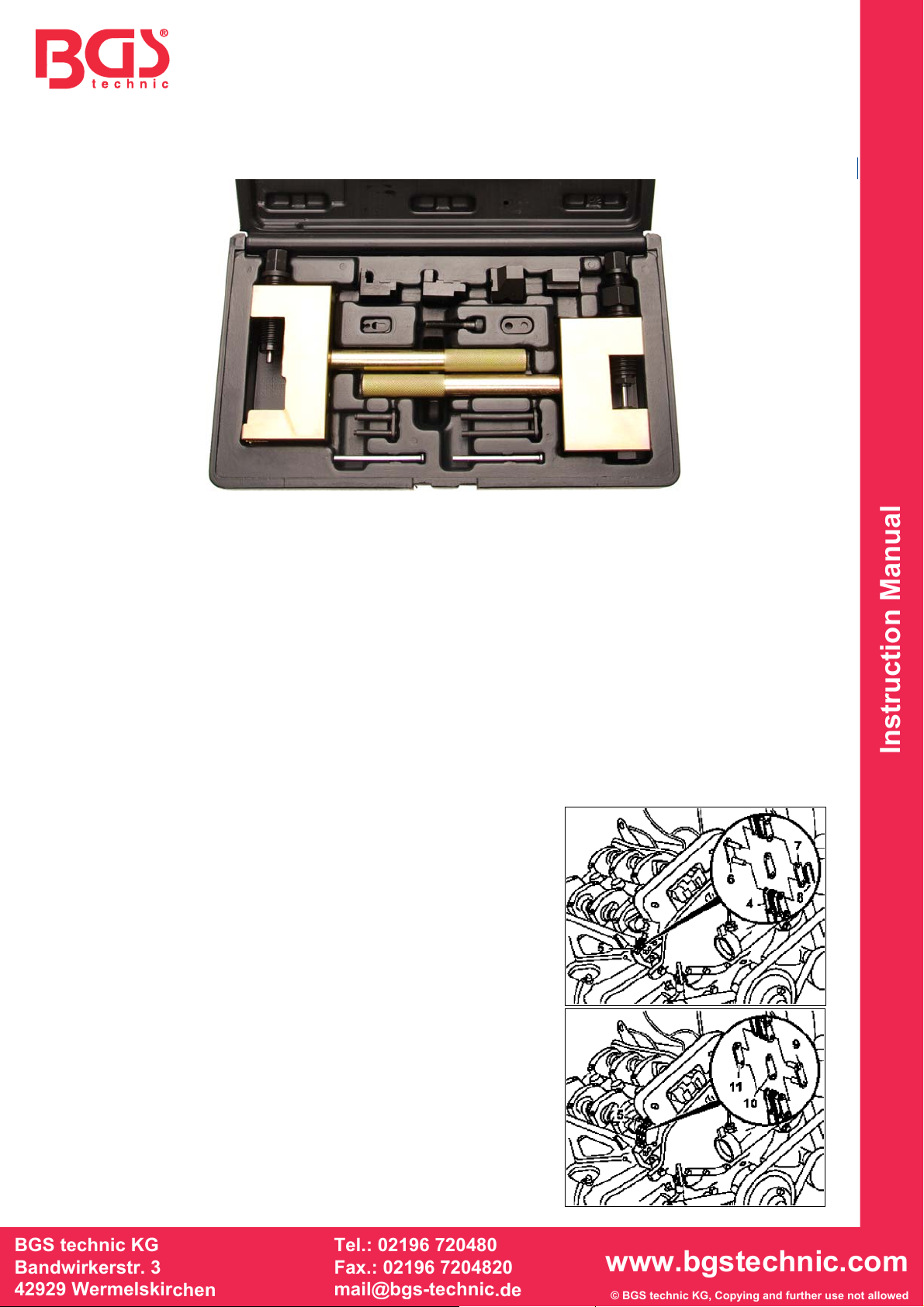
BGS 8501
Remachadora de Cadenas de Distribución
INFORMACIÓN GENERAL
La remachadora está diseñada para reparar o remachar las cadenas de distribución. La cadena de
distribución vieja será empujada sobre las ruedas dentadas con la ayuda de la nueva cadena y,
finalmente, queda remachada, lo que hace cualquier desmontaje de la caja de la cadena de
distribución, innecesaria.
INSTRUCCIONES DE SEGURIDAD
No utilice la herramienta con alguna de sus piezas perdidas o dañadas.
Retirar la llave de contacto antes de empezar su trabajo de reparación, con el fin de evitar
cualquier puesta en marcha involuntaria del motor, que daría lugar a un daño en el mismo.
Este manual de instrucciones tiene como propósito proporcionar información básica y no de
ninguna manera sustituir un manual de taller.
Siempre use vehículos manuales de servicio específicos. Se usa para buscar datos técnicos,
como los valores de par, la información sobre el desmontaje / montaje, etc.
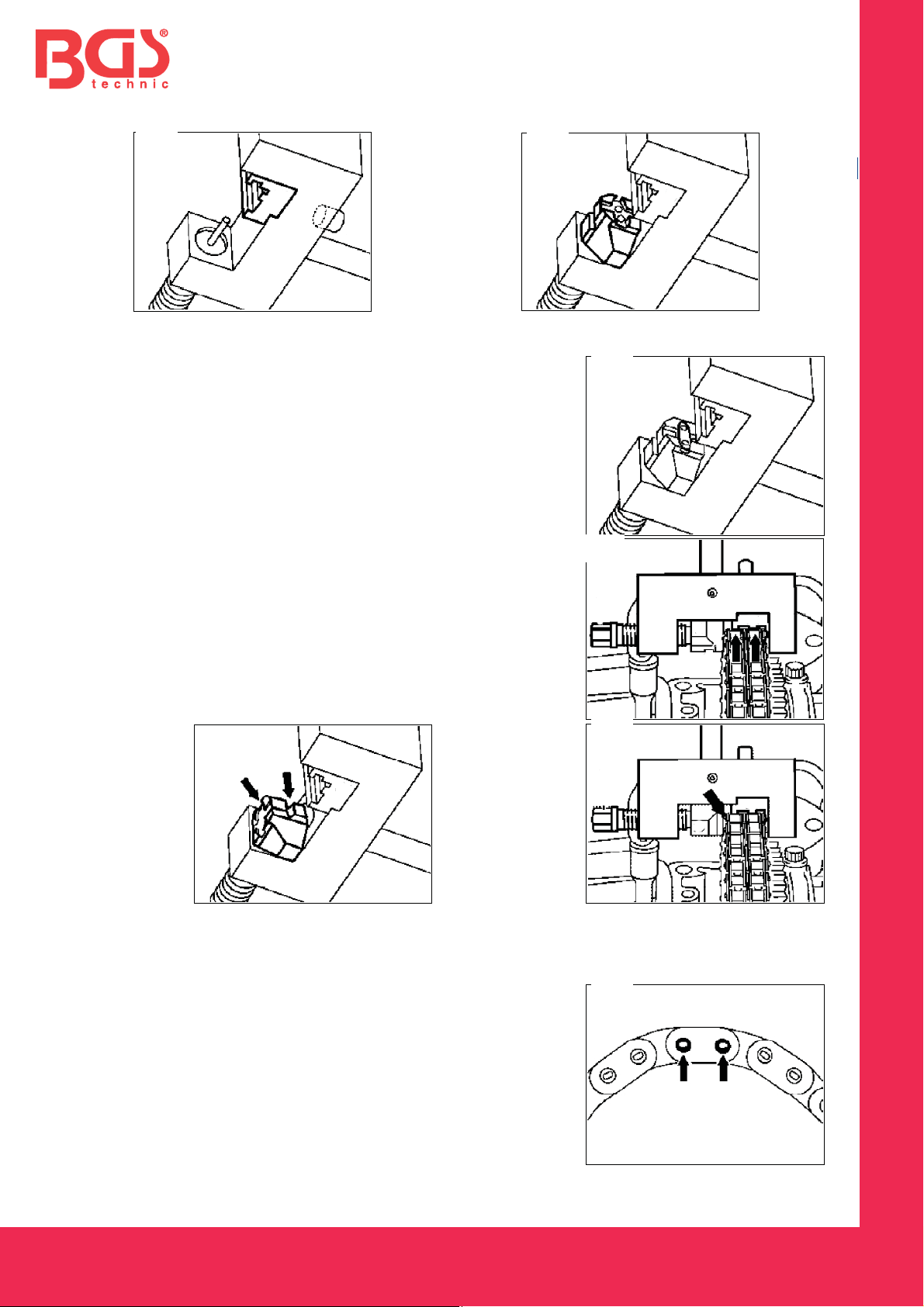
ANWENDUNG
1. Enlazar la nueva cadena de distribución de la vieja cadena
de distribución (4) mediante el enlace de la cadena de
montaje, que consta de articulación (6), la placa (7) y el
cierre (8).
2. Quitar los tornillos de fijación.
3. Girar el cigüeñal lentamente en la dirección de rotación del
motor.
4. Tire del extremo de la cadena de distribución vieja hasta
que se libere, de manera uniforme, fuera de la caja de la
cadena de distribución siendo de la misma medida la
nueva cadena de distribución se arrastra en el interior.
Nota: asegúrese de que la cadena de distribución no salta
mientras se gira.
5. Quite la cadena de distribución de edad.
6. Conecte los extremos de la nueva cadena de distribución,
con el enlace de remachado (9) y la placa central (10).