SW-Stahl und Werkzeugvertriebs GmbH Tel. +49 (0) 2191 / 46438-0
F56essartSresukreveL ax +49 (0) 2191 / 46438-40
ed.lhatsws@ofni:liaM-EdiehcsmeR79824-D
Instruction Manual
BGS technic KG
Bandwirkerstr. 3
42929 Wermelskirchen
Tel.: 02196 720480
Fax.: 02196 7204820
www.bgstechnic.com
© BGS technic KG, Copying and further use not allowed
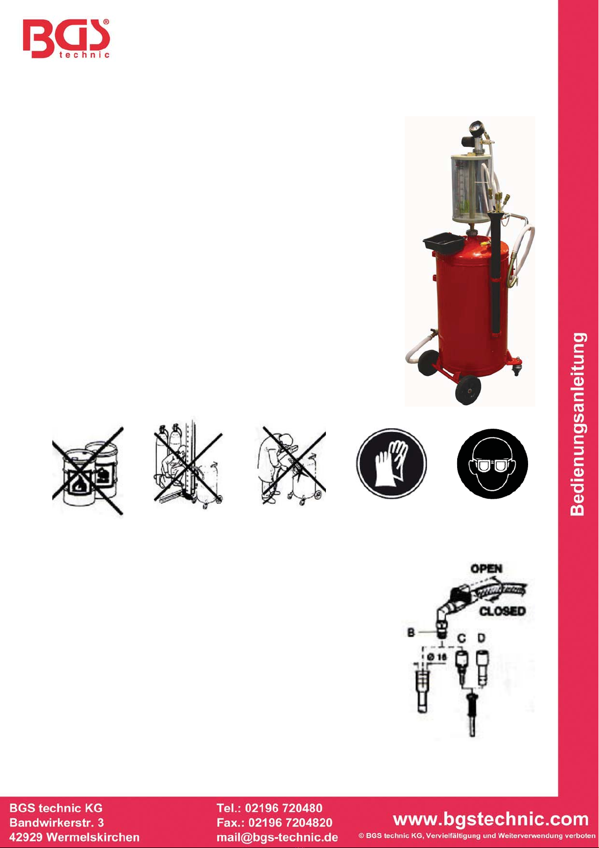
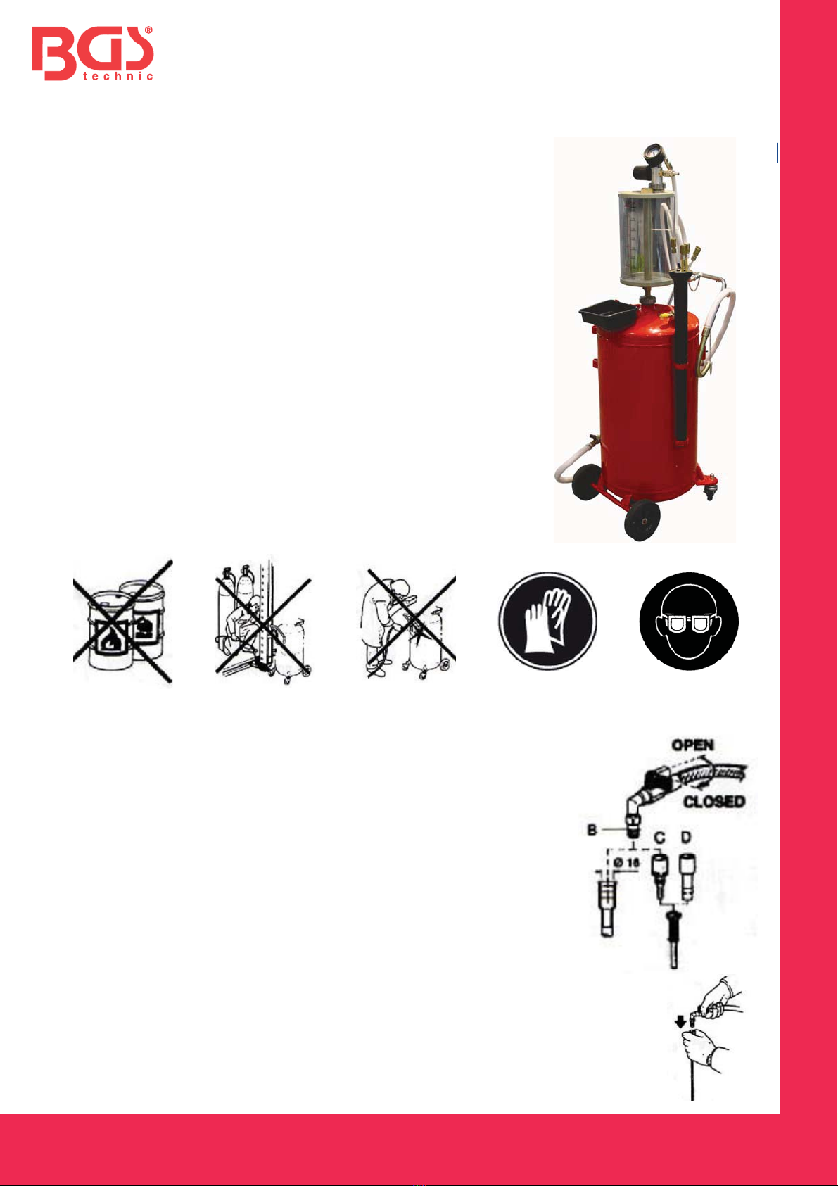
Art. 8545
Vacuum Oil Container, 90L
VOLUME
Total Volume: 90 l
Volume of Oil: 70 l
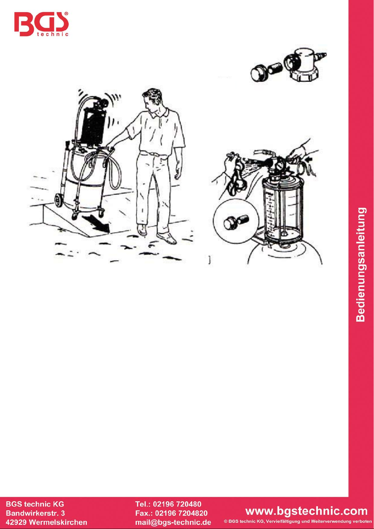
GENERAL
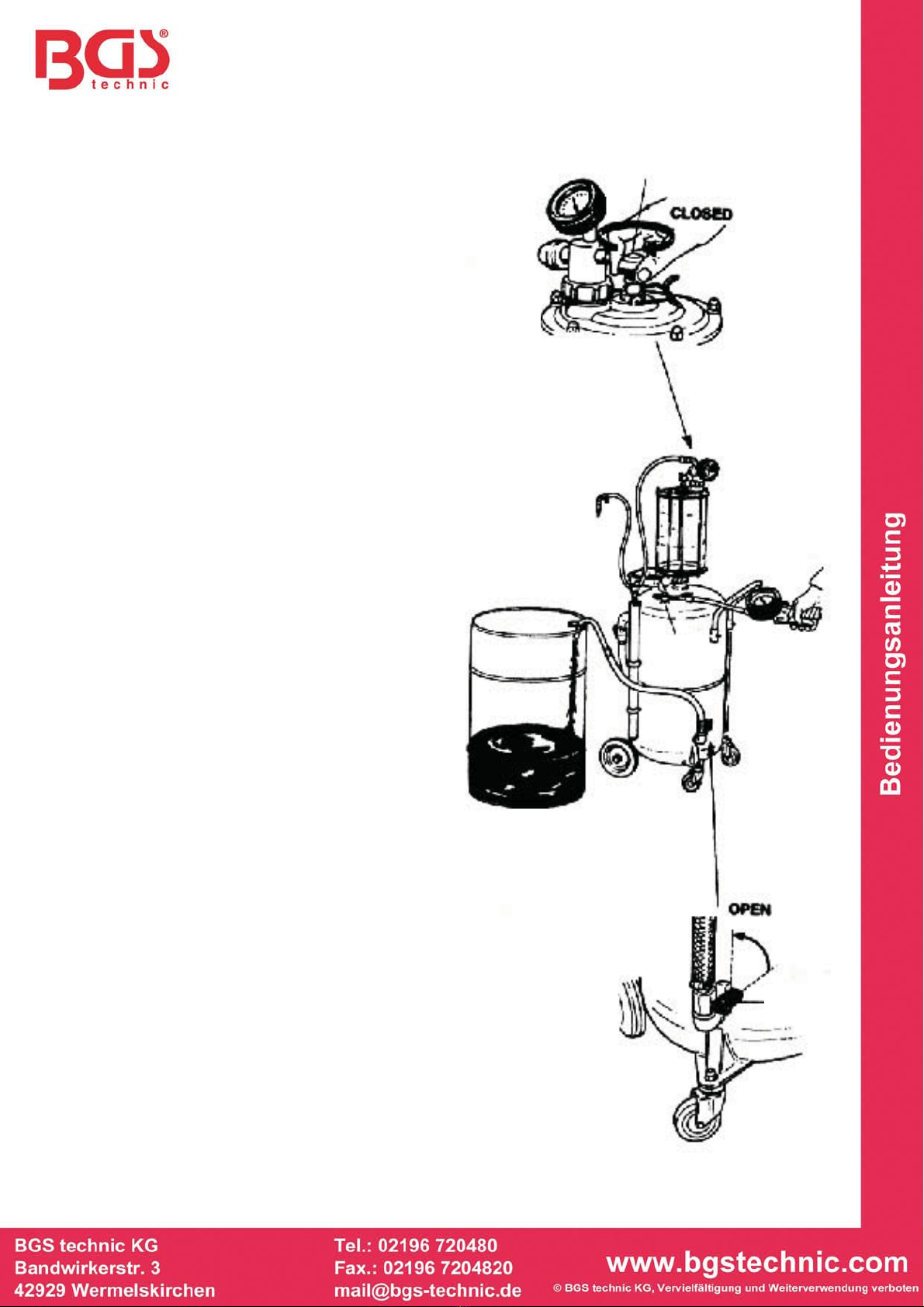
Oil container is designed for suction waste oil, such on engine,
gearbox, rear axle, etc.
WARNING
Do not extract caustic or flammable products.
Do not expose the reservoir to any source of heat.
Do not do any welding on the reservoir.
While extracting oils, keep hands and face protected.
Only use the device for the purpose for which it has been designed.
Do not modify any component of the equipment.
Only use original spare parts.
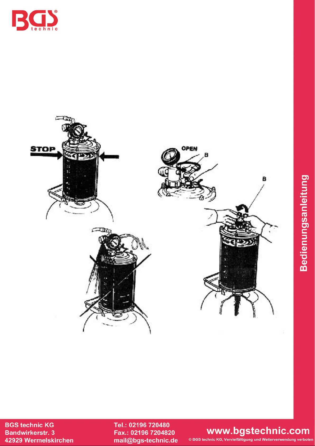
ATTENTION
Some cars have a built-in oil suction probe.
In this case, connect the coupler of the oil changer Bdirectly to the
probe.
For other makes of car (Volkswagen-BMW) equipped with a built-in
probe having a different opening, connector (C-Volkswagen, D-BMW)
must be used.