BHM Medical VOYAGER 550 User manual

IMPORTANT: Read these instructions before installing, operating, or servicing this system
VOYAGER
®
550
BATTERY AND ELECTRIC VERSION
2 AND 4 FUNCTION
CEILING
LIFT SYSTEM
BHM MEDICAL INC., 2001 TANGUAY STREET, MAGOG, QUEBEC, CANADA, JIX 5Y5
Technical Manual Part #001.08865
TECHNICAL MANUAL
Revision 4, August 2002
DO NOT DESTROY

Technical-VOYAGER-550 2
.
Medical Inc. designs and manufactures quality
engineered patient lifting equipment for the care of the disabled in
hospitals, nursing homes and home care.
Please take the time to read the entire manual, including the section on Safety Instructions and Warnings.
It contains important information that will allow you to take advantage of all the characteristics of your
BHM patient lift.
BHM Medical Inc. Credentials
• FDA Registration # 9681684
• CE mark (European Union Listing)
• Global operations for in-warranty and out-of-warranty service support for Voyager Series lift.
• Each finished Voyager Series is individually tested in our laboratory.
• Lifting capacity ranges from 190-360 kg (420-800 lbs.). Engineering safety factor exceeds European
Standards.
• Complete range of patient lift slings and supports designed and manufactured by BHM Medical Inc.
using medical quality materials and fabrics.
• ISO 9001
• Voyager is a registered trademark of BHM Medical inc.
APPROVALS:
CSA 601.1
UL 2601.1
EN 60601.1
EN ISO 10535 (Lifting device) SGS
UK Test Report: DUR22107/AC/OO
Note: BHM Medical is constantly improving its products. For this reason, it may be possible to
encounter a modification of product without revision of this guide.
Thank you for trusting your BHM Medical Partners.
How to contact us:
North America: BHM Medical Inc.
2001 Tanguay Street
Magog (Quebec)
Canada J1X 5Y5
Phone: (819) 868-0441
service calls during business hours - extension #109
(8:00-12:00 and 1:00-5:00 p.m. E.S.T.)
service calls outside regular business hours
extension #6199 (you must press the pound key)
Fax: (819) 868-2249
Web site: www.bhm-medical.com
E-mail: [email protected]
BHM

TABLE OF CONTENTS
Technical-VOYAGER-550 3
INTRODUCTION ............................................................................................................. 4
How to use this Manual.............................................................................................................................. 4
Equipment Identification............................................................................................................................. 4
Receipt of Equipment................................................................................................................................. 4
Key to Symbols .......................................................................................................................................... 4
DESCRIPTION OF EQUIPMENT.................................................................................... 7
Lift Unit ....................................................................................................................................................... 7
What's included.......................................................................................................................................... 7
Parts Description........................................................................................................................................ 7
Dimensions ................................................................................................................................................ 7
OPERATION ................................................................................................................... 8
How to use Voyager 550............................................................................................................................ 8
Emergency Stop ........................................................................................................................................ 9
Emergency Lowering Feature.................................................................................................................... 9
Battery Information................................................................................................................................... 10
Charger Specification:.............................................................................................................................. 11
MAINTENANCE ............................................................................................................ 11
Daily Check List ....................................................................................................................................... 11
Inspection and Cleaning .......................................................................................................................... 11
Strap Inspection ....................................................................................................................................... 11
Lubrication ............................................................................................................................................... 12
Handling and Storage .............................................................................................................................. 12
Battery Replacement ............................................................................................................................... 12
Strap Replacement .................................................................................................................................. 13
Drum Replacement .................................................................................................................................. 14
Horizontal Motor Replacement ................................................................................................................ 15
Vertical Motor Replacement..................................................................................................................... 16
Limit Switch Replacement........................................................................................................................ 16
Limit Switch Rod Replacement ................................................................................................................ 17
Maintenance Inspection Checklist ........................................................................................................... 18
TROUBLESHOOTING .................................................................................................. 20
PARTS LIST.................................................................................................................. 22
ACCESSORIES ............................................................................................................ 28
WARRANTY.................................................................................................................. 29

INTRODUCTION
Technical-VOYAGER-550 (REV 4) 4
INTRODUCTION
How to use this Manual
DO NOT ATTEMPT TO USE THIS
EQUIPMENT WITHOUT UNDER-
STANDING THIS MANUAL.
To ensure safe operation, read the entire
manual carefully, especially the section on
“Safety Instructions and Warnings”, before
installing, operating, or servicing this
equipment.
If anything is not completely understood,
please contact your supplier for more
details. Failure to comply with warnings in
this manual may result in injury.
Keep this manual with the lift and refer to it
as required. Contents of this manual are
subject to change without prior notice to
users.
Throughout this manual, the following symbols
may appear. Pay particular attention to the
information provided under these headings.
These special annotations are easily recognised
as follows:
WARNING: this symbol is
intended to alert the user to
hazards or unsafe practices,
which could result in serious
bodily harm.
CAUTION: this symbol is intended
to alert the user of the presence of
important operating and
maintenance instructions, which
could prevent product damage or
possible personal injury.
NOTE: this symbol offers helpful
information concerning certain
operating procedures.
Additional copies of this manual can be
purchased by contacting your supplier. Include
the User Manual product number and equipment
identification numbers.
Equipment Identification
The unit's identification number (specification,
model, serial number) appears on a silver
nameplate attached to the back of base.
Receipt of Equipment
Upon receipt of the equipment, verify it against
the packing list to ensure it is complete and
inspect the equipment for possible damage due
to shipping. If there is any damage, DO NOT
USE the equipment and notify the carrier
immediately to file a claim. Provide complete
information concerning damage claims or
shipping errors to your supplier. Include all
equipment identification numbers and group part
numbers (if any) as described above along with
a full description of damaged parts.
Key to Symbols
The following symbols are used on lifter’s
attachment labels:
This symbol is required to be displayed
on regulated products for sale in the
European Market. It indicates that the
product complies with applicable
European Directives related to health,
safety, environment and consumer
protection.
Safe Working Load represents the
maximum load the lifter is rated for safe
operation.
The following symbols are used on sling labels
and related to washing instructions:
Maximum washing temperature 60°C
(140°F) permanent cycle.
Do not use bleach.
Do not dry clean.
Tumble dry low temperature.
Do not iron.
Please refer to individual sling labels for
complete instructions regarding washing and
drying.
SWL
60ºC

SAFETY INSTRUCTIONS AND WARNINGS
Technical-VOYAGER-550 (REV 4) 5
SAFETY INSTRUCTIONS AND WARNINGS
A. GENERAL
IMPORTANT – READ THESE INSTRUCTIONS CAREFULLY OR SERIOUS INJURY MAY RESULT.
KEEP THESE INSTRUCTIONS AND THE KEY PROVIDED WITH THE LIFT AT ALL TIMES.
READ OPERATION AND MAINTENANCE INSTRUCTIONS IN THIS MANUAL BEFORE
INSTALLING, OPERATING, OR SERVICING THIS EQUIPMENT.
An authorized contractor or installer must install BHM Medical ceiling lifts.
YOUR LIFT is for transferring patients only. Do not use the lift for any other purpose.
ALWAYS carry out the daily checklist before using the lift.
BHM Medical ceiling lifts are specifically designed for BHM Medical ceiling rail systems, slings
and accessories. Slings and accessories designed by any other manufacturer are prohibited
and will void BHM Medical’s warranty. Use only BHM Medical slings and accessories to
maintain patient safety and product utility.
BHM Medical ceiling lifts are intended to be used for patients within the specified weight limit
indicated for the lift. Do not attempt to lift more than the weight limit indicated.
Before attempting to transfer, the patient must be assessed by a qualified professional.
BHM Medical ceiling lifts must be used by a caregiver with proper training to work with the
patient to be transferred.
ONLY trained and qualified caregivers should transfer a patient. DO NOT attempt to use the lift
if you have not been properly trained to do so.
ALWAYS be prepared before attempting to transfer a patient.
DO NOT use a sling that is not recommended for the lift.
NEVER use a damaged, torn or frayed sling.
ALWAYS place the sling around the patient according to the instructions enclosed.
FOLLOW lifting procedures outlined in this manual.
USE all controls and safety features only according to the rules specified in this manual.
Never attempt to force a control or button on the lift.
DO NOT store the charger in a shower, bath or other areas with high humidity.
DO NOT drop the patient lift or battery. Dropping the battery or lift may cause internal damage
that is not easily seen. If lift is suspected to be damaged, take to an authorized technician for
servicing.
IMPORTANT: Keep all components of the lift clean and dry, and have electrical and mechanical
safety checkpoints done as instructed in the Maintenance section of this manual.
Replace any precautionary or instruction labels that cannot be easily read.
• Avoid violent shock during transportation.
B. SHOCK PREVENTION
DO NOT touch or use a lift with bare conductors or a damaged power cord. Electrically live
equipment can electrocute a patient. If the lift or charger has any exposed or damaged wires
contact your local dealer immediately.
DO NOT cut or remove the round grounding prong from any plug. All BHM lifts are equipped
with three-prong plugs to protect from shock hazard or electrocution. Any two-prong electrical
outlet must be replaced with a properly grounded three-prong outlet according to the National

SAFETY INSTRUCTIONS AND WARNINGS
Technical-VOYAGER-550 6
Electrical Code and local codes. It is the responsibility of the customer to have the work done
by a qualified electrician.
Do not splash or expose electric parts of the device to water or moisture.
Check nameplate for voltage and cycle requirements. These requirements differ by country.
Do not attempt to use the lift in an area that has a different voltage and cycle requirement.
DO NOT attempt to expose, service or repair the lift, battery or charger. If any unit is
malfunctioning, contact your local dealer.
READ the battery and charger instructions thoroughly before using or storing them.
C. FIRE AND EXPLOSION PREVENTION
Batteries may explode, leak and cause personal injury if not disposed of properly
• Do not place or store the battery under direct sunlight or near a heat source
• Do not dispose of in fire
• Do not short the battery terminals
• Do not incinerate
• Flush with water if electrolyte (Acid) comes in contact with skin or eyes.
Batteries must be recycled, disposed of according to local law regulations. When returning
batteries, insulate their terminals with adhesive tape, etc. Otherwise, the residual electricity in
used batteries may cause fire or explosion.
D. EQUIPMENT WARNING LABELS
Inspect all precautionary labels on the equipment. Order and replace all labels that cannot be
easily read.

DESCRIPTION OF EQUIPMENT
Technical-VOYAGER-550 (REV 4) 7
DESCRIPTION OF EQUIPMENT
(Stainless steel model available for chlorinated
area)
Lift Unit
The lift unit is a steel frame based system driven
by a gear reduced high torque motor.
OPERATING FEATURES
• Lifting capacity: 250 kg (550 lbs.)
• Average weight: 22.73 kg (50 lbs.) battery
included.
• Electronic soft-start and soft-stop motor
control.
• Manual and electric emergency lowering
device.
• Emergency brake (in case of mechanical
failure). Operates on the same principle as a
car safety belt mechanism.
• Emergency stopping device.
• Current limit for circuit protection in case of
overload.
• Low battery disconnect system to protect
batteries from being drained.
• Lifting speed: 6 cm/sec. (2.4 in./sec.).
• Horizontal displacement speed: 15 cm/sec.
(6 in./sec.).
• Vertical axis motor: 24 VDC, 1/8HP.
• Horizontal axis motor: 24 VDC, 1/10 HP
• Strap length up 3.6 m (144 inches) tested for
1363.6 kg (3000 lbs.).
• CSA No. 601.1, UL No. 2601-1 and CE
certifications.
• Respects EMI standards.
• ISO 10535.
What's included
ITEM QTY
Voyager 550 lift 1
Battery (inside unit) 1
Integrated Charger Stopper 1
Rail Stopper 1
Handset 1
Carry bar 1
Power cord 1
Instruction manual 1
4 mm Allen Key 1
Parts Description
Dimensions
Power cord
Rail sto
pp
er Fuse magazine
Trolley
Charging light
Handset
Control
switches
Low-battery
indicator
Carry bar
Emergency stop
Emergency
lowering
4-function
2-function
Integrated
char
g
er sto
pp
er
Allen key
Rail
Charger
Stopper for UK
only
Allen key

OPERATION
Technical-VOYAGER-550 (REV 4) 8
OPERATION
How to use Voyager 550
READ "SAFETY INSTRUCTIONS
AND WARNINGS" BEFORE
ATTEMPTING TO USE THE
VOYAGER 550.
Unit will not lower or lift when in
contact with the charger.
1. Install the patient sling
Move the lift directly over the patient.
2. For two-function battery pull the unit
manually directly over the patient or for four
function battery, use the handset.
If the buttons do not operate on
the handset, pull the red cord
gently, once until you hear a
“click”
3. Using the handset button, lower the
carry bar below the patient’s chin (to avoid
the risk of facial contact caused by a sudden
movement of the carry bar) before beginning
to attach the sling straps. If lift will not
operate – pull red cord once gently, until you
hear a click.
Hold the lift carry bar with one
hand at all times when near a
patient.
Note: In a lying down position, lower the
carry bar near the thorax, then install the
straps.
4. Attach the straps to the desired position.
5. Carefully observe the patient to ensure
his/her safety as you press the control button
.
BEFORE LIFTING THE PATIENT :
1. Make sure that all straps are
attached to the carry bar.
2. Make sure the patient is
comfortable.
3. Make sure the sling is not
caught on any obstruction
(wheelchair brake or arm of
chair).
If any of the above occur - lower the patient
immediately and correct the problem.
Lift until the patient's buttock
clears the arm supports or the top
of the bath or bed before moving
the patient. Guide the legs past
any obstacle.
6. When the patient is located
above the desired point of
transfer, press the button.
7. Use the handles on the back
of the sling to position the patient when
transferring into a chair. Hold the handles
firmly as the sling lowers; the sling will tilt
back to position the patient.
8. Once the patient is properly seated and the
straps are loose, remove the sling from the
lift.
Hold the lift carry bar with one hand
at all times when near a patient.
9. Slide the lift away from the patient.
10. When lift is no longer required:
2-function - gently return the unit to charger
manually.
4-function - engage the automatic return to
charger function by pressing .
11. Check the charging indicator light to ensure
the charger is working.
OPERATION
Technical-VOYAGER-550 9
Emergency Stop
(Red cord)
1. This can be activated at any
time to stop the functioning
of the lift.
2. To stop the lift in an
emergency, pull the red cord
once gently, you will hear a
“click”.
Do not pull the red cord
forcefully. If cord pulled too
forcefully, the lift may become
inoperable.
3. When you initially receive your lift the
emergency stop is in the “off” position. To
activate the lift, pull the red cord once gently.
To re-activate pull the red cord once gently,
you will hear a “click”.
Emergency Lowering Feature
(White cord)
In the event of an electrical or
functional failure, the Voyager
550 has an emergency
electrical and manual lowering
feature.
Only to be used in case of an
emergency.
If the lift malfunctions when a patient is being
transferred, the emergency lowering device
provides a safe way of lowering the patient onto
a chair or bed.
To operate the emergency lowering features:
Electrical Version
Move the patient over a bed or a chair, and then
gently pull down on the white cord. If this does
not function then go to step 2.
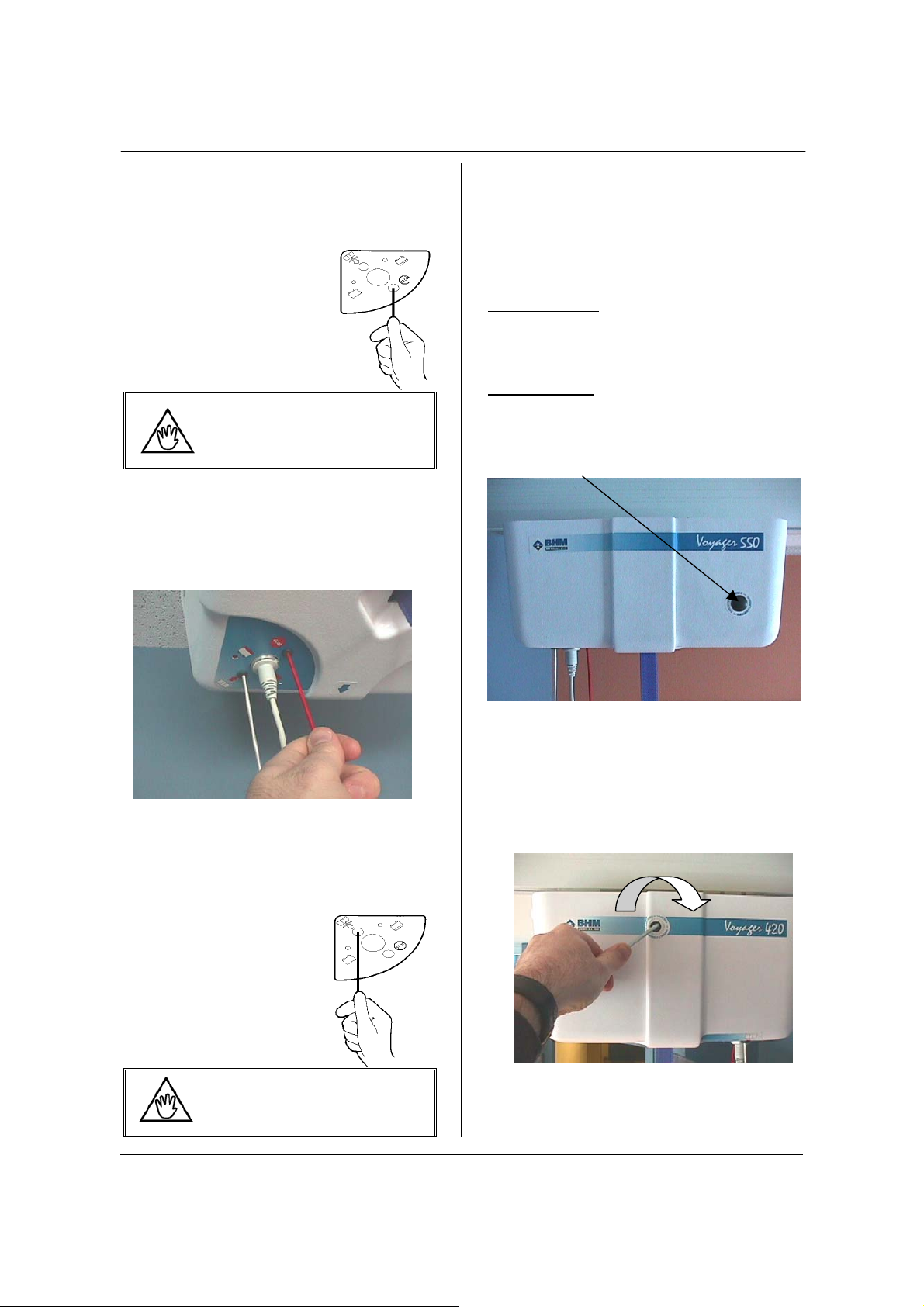
Manual Version:
Find the rubber stopper and label on the side of
the lift.
VOYAGER 550
1. Pull the rubber stopper out of the Voyager
casing – DO NOT DISCARD.
Use the Allen key provided with this
manual, turn the key clockwise to lower the
patient into a chair or bed. As the key turns
the motor directly, each key turn will move
the patient slightly
.
To lower the patient more quickly, use a
power drill with a 4 mm Allen key bit.

OPERATION
Technical-VOYAGER-550 10
2. Once the patient is lowered safely into a
chair or bed, call a certified technician to
have lift serviced.
Emergency Brake
•
The emergency brake is
made of a metal bar
fixed to the drum.
•
In case of a chain, gear or motor breakage,
the centrifugal force created would block the
bar against the frame.
Frame with mechanical clips
•
Supporting structure is welded
and reinforced with metal
clips.
Battery Information
• 24 Vdc, 7 Ah rechargeable battery.
• Provides up to 150 transfers with load of 75
kg (165 pounds).
Life cycle (number of charging cycles) of the
battery is largely dependent on the depth of
discharge in each cycle. The more the battery is
drained the shorter its life span. The life of the
battery is also related to such factors as varying
temperatures and rest periods between charge
and discharge.
Graph 1: Number of recharges vs. Depth of
discharge
Graph 1 illustrates the relationship between
discharging depth and expected battery life.
If you drain the battery until it beeps every time,
you can expect the battery to fully charge only
600 times.
To prolong battery life – Return
the lift to the charger WHENEVER
THE LIFT IS NOT IN USE.
The battery will not overcharge.
BHM uses sealed lead-acid batteries.
Contrary to nickel-cadmium, BHM batteries
do not have any memory effect. Therefore,
batteries should not be completely drained
before recharge.
Graph 2: Number of lifts vs. Lift load
The graph above (Graph 2) illustrates the
relationship between the load lifted and the
number of lifts that can be done with one
recharged battery.
Do not drain the battery
excessively. This will
dramatically reduce the battery
life span.
If the low battery buzzer sounds and red
light flashes, be sure to recharge the battery
as soon as possible.
Charging the battery
DO NOT operate the charger unit
with a damaged cord or if the unit
has been dropped or damaged.
DO NOT forcibly bend the power cord or
place a heavy object on it. This will
damage the cord and may cause fire or
electrical shock.
DO NOT pour liquid on or near the charger.
Do not place the unit in locations
that are:
• Extremely hot
• Dusty or dirty
• Very humid
• Moving or vibrating
The recharging steps should be as follows:
For the 4-function, return to charge and press
0
20
40
60
80
100
120
Charge/discharge cycles
100%
50%
30%
0
50
100
150
200
250
300
350
100 200 300 420
weight
number of lifts

MAINTENANCE
Technical-VOYAGER-550 (REV 4) 11
the button on the handset. The lift cannot
return to charger with a 50-pound load.
For the 2 function, pull the lift gently over to the
charger and ensure it is properly connected.
DO NOT SLIDE THE LIFT OVER TO
THE CHARGER FORCEFULLY OR
QUICKLY. THE CHARGER MAY
BECOME DAMAGED.
• The indicator light will illuminate red to green
depending on the battery drain. If the light
does not go on, check “Troubleshooting”
section in this manual for assistance.
• If the battery is low, the light will show red or
orange when you return the lift to the
charger. The light will gradually turn to
green when fully charged.
Whenever possible leave the lift
on the charger when the lift is not
in use. At minimum, charge the
battery until the light is green
before using it again. This will
extend the life of the battery.
Charger Specification:
• Hospital grade charger cord and plug.
• Charger input: 120 Vac, 60 Hz, 0.5 A. (North
America) / 240 Vac, 50 Hz, 0.25 A
(European).
MAINTENANCE
ALWAYS CARRY OUT THE DAILY
CHECKLIST BEFORE EACH LIFT
USE.
Alterations made to the VOYAGER 550 by
someone other than a certified technician
may cause serious injury and will void
warranty.
The VOYAGER 550 and accessories must
be inspected ANNUALLY by a certified
technician in addition to the daily and other
periodic visual checks done by the user
specified in this section.
Preventive maintenance specified in this
manual can prevent accidents and reduce
repair costs.
Note all service or repairs to the VOYAGER
550 or its accessories in the log book at the
end of this manual. Have the document
signed by the certified technician.
Daily Check List
THE FOLLOWING PROCEDURES MUST
BE FOLLOWED BEFORE EACH USE.
• Has the battery been charged? Park the lift
on the charger whenever the lift is not in use.
• Inspect the lift for any damage. If the lift
casing does not look properly aligned, or
there are any cracks or other damage on the
lift, or any parts are missing - DO NOT USE
IT. Contact your local representative to
have the lift serviced.
• Inspect the visible strap for any signs of
wear, frays, loose threads or other damage.
If there is any evidence of damage- DO NOT
USE IT. Contact your local representative to
have the lift serviced.
• Inspect the sling for tears, frayed straps or
loose stitching. If the sling has any of the
above damage, DO NOT USE IT. Contact
your local representative to have the sling
replaced or repaired.
• Inspect the carry bar for any signs of
cracking or damage.
• Ensure the ring and cotter pins that attach
the carry bar to the strap are secure.
Inspection and Cleaning
Clean the Voyager 550 with a soft dry cloth, or a
soft cloth lightly moistened with a mild detergent
solution. Do not use any type of solvent that may
damage the finish.
Do not immerse lift in water.
To ensure a better rolling surface for the trolley
wheels, clean the inside of the track every 4
months. To do so, insert a damp cloth in the
opening and slide it from one end of the track to
the other.
Always reinstall rail end stoppers
(if they have been removed) after
servicing.
Strap Inspection
This equipment is built with a strap that can
withstand a load of 1364 kg (3000 lbs.).
Nonetheless, if this strap is damaged or shows
signs of wear, the acceptable load on the strap
before rupture can drop rapidly and present a
danger for the patient and/or caregiver.

MAINTENANCE
Technical-VOYAGER-550 12
BHM Medical recommends thoroughly
inspecting the strap every 2 months as follows:
1. Completely unwind the strap.
2. Look for any signs of wear:
If there is any sign of wear as
indicated above or any other
visual defect, strap should be
changed immediately. By
continuing to use the lift without
changing the strap, caregiver and
patient safety is greatly
compromised.
In any case, the manufacturer recommends
changing the strap at least every two years.
By continuing to use the lift without
changing the strap, caregiver and patient
safety is greatly compromised.
Lubrication
Even if lubrication is not mandatory, we
recommend putting white grease machinery
grade and NLGI 2 type on drum teeth to reduce
friction once a year.
Handling and Storage
Avoid violent shock during transportation.
The lift should not remain stored for long periods
of time without recharging the batteries.
BHM Medical recommends
charging of batteries at least every
two weeks even if the lift is not
used. This will prevent premature
aging of batteries.
Battery Replacement
BHM uses sealed lead-acid batteries. Contrary
to nickel-cadmium, BHM batteries do not have
any memory effect. Therefore, batteries should
not be completely discharged before recharge.
Battery life expectancy is 3000 cycles (average
of 165 pounds and 24 inches travel and 30%
deep of discharge). The 3000 lift cycles
represent the "half-capacity" of the battery,
meaning that the battery is half of a new one.
After this half-capacity, the battery will degrade
rapidly. Therefore, we recommend changing for
a new one.
1. Place the VOYAGER 550 on a solid table.
You can use two pieces of wood to secure
the unit to avoid breaking the trolley.
Remove the cab from the chassis by
unclipping the 4 screw caps with a small
blade and use an 8 mm socket to unscrew
the 4 screws.
2. Unplug red/white and black/white wires from
batteries. Unplug the blue jumper. Unscrew
nuts (8 mm socket) which are retaining
batteries support. Do not completely
unscrew. Unscrew until batteries are loose.
3. Remove batteries and replace them by new
batteries. Tighten nuts (8 mm socket) and
plug in the blue jumper. Plug black/white and
red/white wires. Be careful of the colour
code (black = negative, red = positive). You
can use a hot glue gun to affix the wire to the
battery terminal.
4. Replace the cab. Place the cords and the
handset in their respective hole. Screw back
in and put on the screw caps.
Charger Fuse Replacement
If the light does not illuminate when there is a
battery in it, do the following steps:
Loose threads in stitched area.
Noticeable discoloration by having
a
Lighter color strap than the double
Side wear.
Middle wear.
thickness stitched area.

MAINTENANCE
Technical-VOYAGER-550 13
1. Check to make sure the power cord is
correctly plugged into the charger in the
wall.
2. Pull the power cord out of the charger.
Under the socket for the power cord, there
is a drawer or magazine where there are
fuses. Using a pen or screwdriver, pull the
drawer out gently. Pull the burned fuse out
of the drawer that is next to the charger
(see diagram below) and discard. Take the
replacement fuse and place it in the same
slot where the burned fuse was. Slide the
drawer back into the charger. Plug the
power cord into the charger. Place the lift
onto the charger and check for the light.
3. Check the outlet to make sure it has power
to it.
4. If the light does not illuminate, contact your
local dealer or representative for
assistance.
Replace the fuse with the following:
Fuse: GMC 0.5 A 250 V North America (when
input is 120 Vac) Product # C8FGMC0.5
GMC 0.25 A 250 V European (when input
is 240 Vac) Product # C8FGMC0.250
The fuse may also be ordered through your local
dealer or representative.
Charger Fuse Replacement (for UK
only)
If the light does not illuminate when there is a
battery in it, do the following steps:
1. Check to make sure the power cord is
correctly plugged into the charger in the
wall.
2. Disconnect the power cord from the wall.
3. Unscrew the fuse holder cap.
4. Replace the fuse with the following:
Fuse: GMC 0.5 A 250 V North America
(when input is 120 Vac) Product
# C8FGMC0.5
GMC 0.25 A 250 V European
(when input is 240 Vac) Product
# C8FGMC0.250
The fuse may also be ordered through
your local dealer or representative.
5. Screw back the fuse holder cap
Strap Replacement
1. Place the VOYAGER 550 on a solid table.
You can use two pieces of wood to secure
the unit to avoid breaking the trolley.
Remove the cab from the chassis by
unclipping the 4 screw caps with a small
blade and use an 8 mm socket to unscrew
the 4 screws.
2. Activate the white cord and pull the entire
strap out of the drum until you align the drum
screw in front of the second frame hole.
3. Unplug the 15-pin power connector from the
circuit board. Remove the circuit board by
unscrewing the two 5 mm screws.
MAINTENANCE
Technical-VOYAGER-550 14
4. Find the second hole on the frame (circuit
side) and unscrew the long bolt of the drum
and remove the strap
5. Install the new strap in the drum (leather
piece upside: wrong side can disable the
limit switch functions) and screw the long
bolt through the strap to the drum.
6. Unscrew nuts (8 mm socket) which are
retaining batteries support and position the
batteries on the frame to give you access to
the limit switches.
7. Insert the other end of strap through the limit
switch, around the guide roll and slide it
between the two limit switches and the guide
roll. With one hand insert the end of strap
and with the other hand using one finger
push the limit switch and with another finger
guide the strap through the hole.
8. Put the batteries and the battery rack back in
place and screw them in with the two 5 mm
locknuts. Put the circuit board back in place
by screwing the board to the frame with the
two 8 mm screws. Plug the 15-pin power
connector to the circuit board.
9. Plug in the handset and push the up button
until the entire strap rolls on the drum.
10. Replace the cab. Pass the cords and
handset through their respective holes.
Screw back in and put on the screw caps.
NOTE: For the first use of the new strap, rewind
the entire strap with light load (50 lbs.) to give a
proper tension.
Drum Replacement
1. Place the VOYAGER 550 on a solid table.
You can use two piece of wood to secure the
unit to avoid breaking the trolley. Remove
the cab from the chassis by unclipping the 4
screw caps with a small blade and use an 8
mm socket to unscrew the 4 screws.
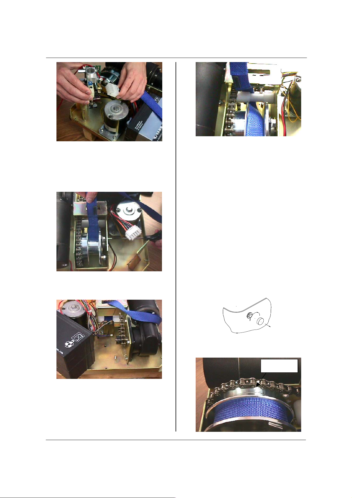
2. Pull the white cord and turn the drum until
you place the connecting link of the chain at
an upper position.
Connecting
link

MAINTENANCE
Technical-VOYAGER-550 15
3. Unplug red/white and black/white wires from
batteries. Unscrew nuts (8 mm socket) which
are retaining batteries support. Remove the
battery rack and the batteries.
4. Unplug the 15-pin power connector from the
circuit board. Remove the circuit board by
unscrewing the two 5 mm screws.
5. Remove the connecting link from the chain
and leave the chain down.
6. Remove the snap ring on the center shaft of
drum and pull out the shaft through the
frame. Remove the drum from the frame.
7. Install the new drum to the frame and insert
the shaft through the drum and frame hole.
Put the snap ring back in place.
8. Insert the end of strap through the limit
switch hole. With one hand insert the end of
strap and with the other hand using one
finger push the limit switch and with another
finger guide the strap through the hole.
9. Install the circuit board by screwing in the
two 5 mm screws. Plug the 15-pin power
connector to the circuit board.
10. Replace the batteries. Tighten nuts (8 mm
socket). Plug black/white and red/white
wires. Be careful of the colour code (black =
negative, red = positive). You can use a hot
glue gun to affix the wire to the battery
terminal to prevent against vibration.
11. Replace the cab. Pass the cords and the
handset through their respective holes.
Screw back in again and put on the screw
caps.
Horizontal Motor Replacement
1. Place the VOYAGER 550 on a solid table.
You can use two pieces of wood to secure
the unit to avoid breaking the trolley.
Remove the cab from the chassis by
unclipping the 4 screw caps with a small
blade; use an 8 mm socket to unscrew the 4
screws.
2. Unplug the 15-pin power connector from the
circuit board. Remove the motor by
unscrewing the four (4) 6 mm nuts. Unplug
the motor from the 15-pin power connector
with a pin extractor tool. Identify their
respective positions (+) and (-).

MAINTENANCE
Technical-VOYAGER-550 16
3. Put the new motor in place. Screw the motor
to the frame with the four (4) 6 mm bolts and
washers. Install the 2 pin connectors
4. Install the circuit board by screwing in the
two 8 mm screws. Plug the 15-pin power
connector to the circuit board.
5. Replace the cab. Pass the cords and the
handset through their respective holes.
Screw it back on and put on the screw caps.
Vertical Motor Replacement
1. Repeat steps 1 to 5 from the drum
replacement instructions except do not
remove the circuit board.
2. Unplug the motor. Remove the motor by
unscrewing the four (4) 6 mm bolts.
3. Pull the motor out with the sprocket
assembly. Do not separate the sprocket from
the motor. In case of sprocket replacement,
Unscrew the screw with a 1/8 hexagonal key
and gently pull out the drive from the motor
4. shaft by sliding it out.
5. Insert the new motor and screw in it with the
two (2) screws at the bottom. Align the upper
screw and secure it in place. Tighten the 2
other screw.
6. Replace the cab. Pass the cords and the
handset through their respective holes.
Screw back in and put on the screw caps.
Limit Switch Replacement
(For models before serial number ABL2-*F*-
1644)
1. Repeat 1 and 5 from the drum replacement
instructions.
2. Unplug the 15-pin power connector from the
circuit board. Remove the retaining ring on
the center shaft of strap guide roll and pull
the shaft out through the frame. Pull out the
strap guide roll from the frame.
3. Remove the strap guide roll with the center
shaft and snap ring.
4. Remove the limit switch by unscrewing the
½ in. nut.
5. Unpin the limit switch from the 15-pin
connector and replace by the new one.
6. Put the strap guide roll in place with the
center shaft and snap ring.
7. Plug the 15-pin power connector to the
circuit board. Replace the cab. Pass the
cords and the handset through their
respective holes. Screw back in and put on
the screw caps.
(For models after serial number ABL2-*F*-
1644)
1. Repeat 1 and 2 from the horizontal motor
replacement instructions.
2. Unplug, in order, the purple, blue and gray
wires from the limit switch.

MAINTENANCE
Technical-VOYAGER-550 17
3. Unscrew the 2 screws with a flat tip
screwdriver and the appropriate key.
4. Remove the limit switch and replace it by a
new one.
5. Screw back in the 2 screws of the new limit
switch.
6. Plug back, in order, the purple, blue and
grey wires.
7. Put the horizontal motor in place. Screw the
motor to the frame with the four (4) 6 mm
bolts and washers. Install the 2 pin
connectors.
8. Install the circuit board by screwing in the
two 8 mm screws. Plug the 15-pin power
connector to the circuit board.
9. Replace the cab. Pass the cords and
handset through their respective holes.
Screw it back on and put on the screw caps.
Limit Switch Rod Replacement
1. Repeat 1 and 2 from the horizontal motor
replacement instructions.
2. Repeat step 1 to 3 from the vertical motor
replacement instructions.
3. Drill out the rivet that holds the limit switch
rod.
4. Remove the spring that holds the rod.
5. Pull out the limit switch rod.
6. Insert the new rod and hold in place by
popping the rivet as shown in the diagram
below.
7. Put the spring back on.
8. Insert the vertical motor and screw in it with
the two (2) screws at the bottom. Align the
upper screw and secure it in place. Tight the
2 other screws.
9. Put the horizontal motor in place. Screw the
motor to the frame with the four (4) 6 mm
bolts and washers. Install the 2 pin
connectors.
10. Install the circuit board by screwing in the
two 8 mm screws. Plug the 15-pin power
connector to the circuit board.
11. Replace the cab. Pass the cords and
handset through their respective holes.
Screw it back on and put on the screw caps.
Purple Blue
Grey
Spring

MAINTENANCE INSPECTION CHECKLIST
Technical-VOYAGER-550 18
Maintenance Inspection Checklist
THING TO BE INSPECTED BY USER
ITEM INITIALLY BEFORE
EVERY
USE
EVERY 2
MONTH
EVERY 6
MONTH
EVERY
YEAR
EVERY 2
YEARS
LIFT DEVICE
Inspect for missing hardware or broken panel. X X X
Inspect strap for wear. X X
Recharging battery X
Inspect trolley in rail for damage, rust or cracks.
Replace if damaged.
X
Overall inspection by authorized personnel. X
SLINGS AND HARDWARE
Check all sling attachments for sign of wear. X
Inspect sling material for wear or deterioration. X
Inspect sling straps for wear. X
Inspect for any defect or loose threads
in the "stitched areas".
X
Cleaning sling as indicated on the tag. When Necessary
Verify strap extension for wear.
Check stitching and check for degradation due to
chemical attack
X
Verify emergency stop cord for wear. X
Verify emergency lowering cord for wear. X
Replace strap. X
Completely unwind the strap and check stitching and
fraying and check for degradation due to chemical
attack.
X
Check the carry bar for freedom of rotation. X
Check for wear on the central pivot of the carry bar and
lubricate it with any light, mineral based grease.
X
Inspect carry bar connecting joint for proper
attachment.
X
Check for presence and correct fitting of the split rings
on the carry bar.
X
Inspect for excessive wear on the sling hooks and any
side suspenders used in conjunction with the spreader
bar.
X
Check for adequate padding of the carry bar. X
Inspect sprockets and chain for wear. X
Lubricate chain and sprockets. X
Inspect trolley wheels for damage, carrying or rust.
Check also the wear on the axles and check for firm
attachment.
X

MAINTENANCE INSPECTION CHECKLIST
Technical-VOYAGER-550 19
ITEM INITIALLY BEFORE
EVERY
USE
EVERY 2
MONTH
EVERY 6
MONTH
EVERY
YEAR
EVERY 2
YEARS
Inspect the welding aspect on the frame to detect
cracks.
X
Inspect connecting joints for proper attachment. X
Confirm the correct operation of the emergency brake
by making sure it is moving freely on the drum.
X
Confirm correct function of the mechanical emergency
lower.
X
Check for firm fixing of the charger to the track. X
Confirm correct mating of the lift to the charger. X
Confirm correct functioning of the charger. X
Check corrects fuse rating. X
Check mains lead plug and socket for proper mating,
look for damage, evidence of burning or arcing.
X
Inspect "Quick Release" system for wear. X
Load test with the SWL (maximum capacity). X
Maintenance inspection points are suggested by the manufacturer. However, in certain
case, some inspections should be done on a more frequent basis. By continuing to use
the lift without replace the listed parts in this maintenance, caregiver and patient safety is
greatly compromised.

TROUBLESHOOTING
Technical-VOYAGER-550 (REV 4) 20
TROUBLESHOOTING
ELECTRICAL SHOCK HAZARD – Before checking electrical components, remove fuses,
unplug the device or disconnect battery.
CAUTION: HIGH VOLTAGE FROM TEST EQUIPMENT can damage electronic circuit and
other parts.
What might seem to be a power failure is not always the case. First check the following:
PROBLEMS TO CHECK
The unit starts and stops repetitively • If the load is over the safe working load, the unit will not
work due to an overload protection on the motor.
• Has the lift been making a “beeping” sound? The battery is
low and needs to be charged.
The lift emits a "beep" and a red light
flashes during utilisation. The unit may
stop lifting but you can still lower it.
• Batteries are low, return to charger.
Charge indicator on the lift (green-red)
doesn't light up when the lift is on the
charger
• Is the charger stopper plugged into a standard outlet? If so
does the outlet have power?
• Check the condition of the fuse. If needed, change it with a
spare one. (see “Maintenance” section of this manual)
Battery is always dead after a few
transfers. (3 to 5)
• Replace battery with a new one, the life of the current one
is probably nearly over.
(Contact your local dealer or representative to have battery
replaced)
The light on the charger shows green yet
the lift will only do one or two transfers.
• Contact your local dealer or representative to have battery
replaced.
The light on the charger shows green yet
the lift will only work when there is no
one in the lift. When you attempt to
transfer someone, the lift stops.
• Contact your local dealer or representative to have battery
replaced.
The lift does not work when you press
the buttons on the handset
• Is the charger light on? Lift must be moved away from the
charger in order to operate.
• Is the emergency stop activated? Gently pull the red cord
once until you hear a ‘click’. Try the buttons again.
• Is the handset properly plugged into the lift? The handset
may be slightly pulled out of its socket yet appear as
though it is plugged in. The lip of the handset must be
flush with the cab of the lift. The socket and handset
connector is a tight fit – press firmly to ensure the handset
is plugged in properly.
• If the handset was not properly plugged into the lift, it may
be necessary to gently pull the red cord once again.
• Slide the lift over to the charger. Is the light red or not on
at all? Battery likely needs to be charged. See
troubleshooting situations above for more information.
• If, after testing all of the above, the lift will not operate,
contact your local dealer or representative.
The charging light on the lift remains
red and does not turn to green after an
overnight charge.
• If available, try another integrated charger stopper from
another lift or a spare one; plug it into the rail and charge
for 3 hours. If the light does not change to white or green,
contact your local dealer or representative.
• Using a voltage meter, test the two contact points on the
Table of contents
Other BHM Medical Lifting System manuals


Popular Lifting System manuals by other brands


stellar labs
stellar labs Slider40 owner's manual

Pride Mobility
Pride Mobility Go-Go Travel Lift owner's manual

Savaria
Savaria M2LIFT-40 owner's manual

matev
matev FPS-JD 3036 Original operating manual

Skyjack
Skyjack SJ40 T+ Operation manual

WERTHER INTERNATIONAL
WERTHER INTERNATIONAL MONOLIFT 800 Instruction and maintenance manual


