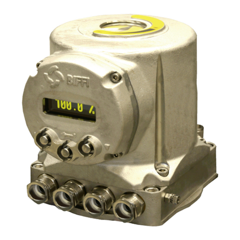
BIFFI ICON3000 Series User manual

Installation, Operation and Maintenance Manual
MDE 254 Rev. 1
March 2021
Biffi ICON3000
HART Bus Module
Copyright © Biffi. The information in this document is subject to change without notice. Updated data sheets can be obtained from our website www.biffi.it or from your nearest Biffi Center:
Biffi Italia s.r.l. - Strada Biffi 165, 29017 Fiorenzuola d'Arda (PC) – Italy PH: +39 0523 944 411 – [email protected]

Revision Details
March 2021
Installation, Operation and Maintenance Manual
MDE 254 Rev. 1
Revision Details
Revision Details
Rev. Date Description Prepared Checked Approved
1 March 2021 General update (Migration to new template)
0 July 2018 First Issue L. Piacenti A. Battaglia

i
Installation, Operation and Maintenance Manual
MDE 254 Rev. 1
Table of Contents
March 2021
Table of Contents
Table of Contents
Section 1: Introduction
Introduction............................................................................................................1
Section 2: Operation and Storage
Operation and Storage.......................................................................................................2
Section 3: Communication Features
Communication Features...................................................................................................3
Section 4: HART Module
4.1 On Board Indications and Jumpers................................................................. 5
4.2 On Board Settings ......................................................................................... 5
4.3 Analogue Control Signal................................................................................ 6
4.4 Process Variables........................................................................................... 6
Section 5: HART Protocol Previews
5.1 HART Wirings................................................................................................ 8
Section 6: Wiring and Installation
6.1 Cable length................................................................................................ 10
6.2 Shielding and Grounding............................................................................. 10
Section 7: HART Commands
HART Commands..............................................................................................................11
Section 8: HART Command Set
8.1 Universal Commands .................................................................................. 13
8.1.1 Command #0: Read Unique Identifier ............................................... 13
8.1.2 Command #1: Read Primary Variable................................................ 14
8.1.3 Command #2: Read Loop Current and Percent of Range ................... 15
8.1.4 Command #3: Read Dynamic Variables and Loop Current................. 15
8.1.5 Command #6: Write Polling Address ................................................ 16
8.1.6 Command #7: Read Loop Configuration ........................................... 17
8.1.7 Command #8: Read Dynamic Variable Classifications ....................... 17
8.1.8 Command #9: Read Device Variables with Status.............................. 18
8.1.9 Command #11: Read Unique Identifier Associated with Tag ..................20
8.1.10 Command #12: Read Message ......................................................... 21
8.1.11 Command #13: Read Tag, Descriptor, Date....................................... 21
8.1.12 Command #14: Read Primary Variable Transducer Information ........ 22
8.1.13 Command #15: Read Device Information ......................................... 22
8.1.14 Command #16: Read Final Assembly Number .................................. 23
8.1.15 Command #17: Write Message ........................................................ 23
8.1.16 Command #18: Write Tag, Descriptor, Date...................................... 24

ii
Table of Contents
March 2021
Installation, Operation and Maintenance Manual
MDE 254 Rev. 1
Table of Contents
8.1.17 Command #19: Write Final Assembly Number ................................. 25
8.1.18 Command #20: Read Long Tag ......................................................... 25
8.1.19 Command #21: Read Unique Identifier Associated with Long Tag ..... 26
8.1.20 Command #22: Write Long Tag ........................................................ 27
8.1.21 Command #38: Reset Configuration changed Flag ........................... 27
8.1.22 Command #48: Read Additional Device Status ................................. 28
8.2 Common Practice Commands..................................................................... 30
8.2.1 Command #42: Perform Device Reset ............................................. 30
8.2.2 Command #54: Read Device Variable Information............................ 31
8.2.3 Command #59: Write Number of Response Preambles..................... 32
8.2.4 Command #95: Read Device Communication Statistics.................... 32
8.2.5 Command #103: Write Burst Period ................................................. 33
8.2.6 Command #104: Write Burst Trigger ................................................ 34
8.2.7 Command #105: Read Burst Mode Configuration............................. 35
8.2.8 Command #107: Write Burst Device Variables.................................. 36
8.2.9 Command #108: Write Burst Mode Command Number ................... 37
8.2.10 Command #109: Burst Mode Control ............................................... 38
8.2.11 Catch Device Variable....................................................................... 38
8.3 Device Specific Commands ......................................................................... 39
8.3.1 Command #129: Write Device Variable Value................................... 39
8.3.2 Command #130: Read Array............................................................. 40
8.3.3 Command #131: Write Array............................................................ 40
8.4 Common Tables .......................................................................................... 41
Section 9: Device Variables
9.1 List of Device Variables................................................................................ 45
9.2 Device Variable Status Byte ......................................................................... 46
9.3 Device Variable 0: Commands..................................................................... 47
9.4 Device Variable 1: Actuator Status (1).......................................................... 48
9.5 Device Variable 2: Actuator Status (2).......................................................... 49
9.6 Device Variable 3: Position Request............................................................. 50
9.7 Device Variable 4: Dead Band ...................................................................... 50
9.8 Device Variable 5: Motion Inhibit Time ........................................................ 50
9.9 Device Variable 6: Actuator Alarms (1) ........................................................ 50
9.10 Device Variable 7: Actuator Alarms (2) ........................................................ 51
9.11 Device Variable 8: Actuator Warnings.......................................................... 51
9.12 Device Variable 9: AL – Opening Time ......................................................... 52
9.13 Device Variable 10: AL – Closing Time ......................................................... 52
9.14 Device Variable 11: ESD Action.................................................................... 52
9.15 Device Variable 12: ESD Percent .................................................................. 52
9.16 Device Variable 13: 2SP – Close Direction Status ......................................... 52
9.17 Device Variable 14: 2SP – Close Direction Start Position .............................. 52
9.18 Device Variable 15: 2SP – Close Direction Stop Position............................... 53
9.19 Device Variable 16: 2SP – Close Direction ON Time ..................................... 53
9.20 Device Variable 17: 2SP – Close Direction OFF Time .................................... 53
9.21 Device Variable 18: 2SP – Open Direction Status ......................................... 53
9.22 Device Variable 19: 2SP – Open Direction Start Position.............................. 53
9.23 Device Variable 20: 2SP – Open Direction Stop Position .............................. 53
9.24 Device Variable 21: 2SP – Open Direction ON Time ..................................... 54
9.25 Device Variable 22: 2SP – Open Direction OFF Time .................................... 54

iii
Installation, Operation and Maintenance Manual
MDE 254 Rev. 1
Table of Contents
March 2021
Table of Contents
9.26 Device Variable 23: Fail Safe Action ............................................................. 54
9.27 Device Variable 24: Fail Safe Delay ............................................................... 54
9.28 Device Variable 25: Fail Safe Position ........................................................... 54
9.29 Device Variable 26: Power Supply Type........................................................ 54
9.30 Device Variable 27: Power Supply Voltage ................................................... 55
9.31 Device Variable 28: Power Supply Frequency............................................... 55
9.32 Device Variable 244: Percent Range ............................................................ 55
9.33 Device Variable 245: Loop Current .............................................................. 55
9.34 Device Variable 246: Primary Variable ......................................................... 55
9.35 Device Variable 247: Secondary Variable ..................................................... 55
9.36 Device Variable 248: Tertiary Variable ......................................................... 55
9.37 Device Variable 249: Quaternary Variable.................................................... 55
Section 10: Array Codes
Array Codes........................................................................................................................56
Section 11: Configuration via Local Interface of ICON3000
11.1 BUS Control................................................................................................. 57
11.2 Positioner Function ..................................................................................... 58
11.3 Fail Safe Function ........................................................................................ 59
11.4 Viewing Transmission Info........................................................................... 60
11.5 Actuator Terminal Board ............................................................................. 60
11.6 Bus Signal Failure Indication ........................................................................ 61
Section 12: Certificate of Registration
Certificate of Registration................................................................................................62
Appendix A: HART Command 3 Communication Example
HART Command 3 Communication Example................................................................63
Appendix B:
B.1 Multiple Functionality of ESD Command and Status .................................... 65
B.2 Multiple Functionality of Interlock Command and Status............................. 66

This page is intentionally left blank
Notes
March 2021
Installation, Operation and Maintenance Manual
MDE 254 Rev. 1

Installation, Operation and Maintenance Manual
MDE 254 Rev. 1 March 2021
Introduction 1
Section 1: Introduction
Section 1: Introduction
The ICON HRT2000v4 Module is an electronic module that allows to connect the Biffi ICON3000
actuator to a HART serial communication line. The module complies with HART Protocol Revision 7.2.
The ICON HRT2000v4 has its microprocessor, it’s controlled by a program stored internally, it works
as a pure bus interface and does not affect the actuator control integrity. It is installed inside the
actuator housing and the communication interface is powered from the actuator power supply
module. The HART hardware modem is located on the module board. The data lines are fully isolated
from the actuator electronics.

March 2021
Installation, Operation and Maintenance Manual
MDE 254 Rev. 1
Operation and Storage
2
Section 2: Operation and Storage
Section 2: Operation and Storage
The module is designed to work and to be stored in the same environment of the actuator.

Installation, Operation and Maintenance Manual
MDE 254 Rev. 1 March 2021
Communication Features 3
Section 3: Communication Features
Section 3: Communication Features
Communication Protocol: HART Protocol Revision 7.2
Electrical Interface: 4 - 20 mA analog loop, 2 wire communication
HART Signal: Digital FSK Frequency Shift Keying (Bell 202 standard)
Logical “0” frequency: 2,200 Hz
Logical “1” frequency: 1,200 Hz
Data Rate: Request / response mode – 2/3 updates per second
Optional burst mode – 3/4 updates per second
Data Transmission: Master / Slave and Burst communication modes
Data Byte Structure: 1 start bit, 8 data bits, 1 odd parity bit, 1 stop bit
Command Structure:
Type of Command Structure
Universal Common to all devices
Common practice Optional; used by many devices
Device specific For unique product features
HART Topology: Point to point, Multidrop, Series Connection
Cable Lengths: Maximum twisted pair length — 10,000 ft. (3,048 m)
Maximum multiple twisted pair length — 5,000 ft. (1,524 m)
Electrical Power: Bus powered
Max voltage 36 V
Min voltage 0 V
Device Type: Actuator
Device Impedance: Low Impedance
Temperature: -40 °C, +85 °C
Reversed Polarity Protection: Present
EMC Protections: According to generic standard for industrial environments
EN61000-6-2 and EN 61000-6-4
Manufacturer ID Code: 183 (B7 HEX)
Device Type Code: 126 (7E HEX)

March 2021
Installation, Operation and Maintenance Manual
MDE 254 Rev. 1
HART Module4
Section 4: HART Module
Section 4: HART Module
The module consists in a single PCB that is installed inside the actuator housing. It is connected to the
ICON3000 base card via strip connector.
The internal wiring connects the HART data lines to the actuator terminal board.
Figure 1 Top Side
Figure 2 Bottom Side

Installation, Operation and Maintenance Manual
MDE 254 Rev. 1 March 2021
HART Module 5
Section 4: HART Module
4.1 On Board Indications and Jumpers
Five LEDs are mounted on the HRT2000v4 rev. 1 to give the following indications for the field service.
LEDs indicators are active only when jumper JP2 is closed.
DL1 (green) Power Supply: ON: when the HRT2000v4 module is correctly powered from
the main power supply.
OFF: when the HRT2000v4 module is not correctly powered
from the power supply.
DL2 (green) HART Communication: ON: Data Message received or transmit from
HRT2000v4 interface.
OFF: Silence between Data HART messages.
DL3 (green) 4 - 20 mA Setup: ON: Setup active (SW3 pin 6 in ON).
OFF: Setup not active (SW3 pin 6 in OFF)
DL4 (red) 4 – 20 mA Input Level: ON: Alarm, input level too low (< 2 mA).
OFF: No Alarms
DL5 (red) Data Area Empty: ON: when Data Area on interface card is not yet loaded.
OFF: when Data Area is completely loaded.
BLINK: when Data Area is being read from base card.
JP1: Program jumper. Used to download new firmware on
microcontroller (Manufacturer use only).
JP2: LEDs Jumper. Short this jumper to power LEDs (Default ON).
SW4 / SW1: Pin Reset. Short this jumper to reset the HRT2000v4 module.
4.2 On Board Settings
The HRT2000v4 module is provided of dip switches to change the hardware settings of the module.
The below settings are normally done in factory. Change settings only if authorized
from manufacturer.
• 4 - 20 mA SETUP
This procedure describes how to set the 4 - 20 mA limits for the HART Card Interface.
— 4 mA: connect 4 mA to HART+ and HART-. Move SW3 pin 5 in ON. Move SW3 pin 6
in ON. Wait 2 seconds. Move SW3 pin 6 and then pin 5 in OFF to store 4 mA setting
in data flash memory.
— 20 mA: connect 20 mA to HART+ and HART-. Move SW3 pin 4 in OFF. Move SW3
pin 6 in ON. Wait 2 seconds. Move SW3 pin 6 and then pin 4 in OFF to store 20 mA
setting in data flash memory.
• Filter ON / OFF
To select analog filter type, follow the below procedure:
— Filter OFF: Move SW3 pin 6 in ON. Move SW3 pin 3 in ON. Wait 2 seconds.
Move SW3 pin 6 in OFF to store OFF filter selection.
— Filter ON (default): Move SW3 pin 6 in ON. Move SW3 pin 3 in OFF. Wait 2 seconds.
Move SW3 pin 6 in OFF to store ON filter selection.

March 2021
Installation, Operation and Maintenance Manual
MDE 254 Rev. 1
HART Module6
Section 4: HART Module
• Default configuration (Manufacturer use only)
To select default factory settings, follow the below procedure:
Switch off the power supply to the card. Move SW3 pin 1 to 6 in ON and then switch on power
supply. Default configuration is stored in data flash memory. Move SW3 pin 1 to 6 in OFF.
Be careful, this procedure clears all configurations selected before. In particular,
the 4 - 20 mA settings are changed and Configuration Change Counter is reset.
• Wiring mode
This procedure describes how to set HART Wirings for the HRT2000v4 Interface (see Section 5.1).
— Point to Point: Move SW5 pin 1 and 2 in OFF. Move SW5 pin 3 and 4 in ON.
— Split Range: Move SW5 pin 1 and 2 in OFF. Move SW5 pin 3 and 4 in ON.
— Multidrop: Move SW5 pin 1 and 2 ON. Move SW5 pin 3 and 4 in OFF.
See Section 11 for the Polling address, Device ID number and Mode.
See also Section 8, Universal Command 6 (Write Polling Address).
4.3 Analog Control Signal
Maximum Current: 20.8 mA
Minimum Current: 2 mA
Multidrop Current: 4 mA
The following values are measured according to the HCF_TEST-2 rev 2.2.
Input Impedence: 495 Ohm (in loop control mode)
Input Capacitance: 30,000 pF (in loop control mode)
4.4 Process Variables
PV: Analog 4 - 20 mA signal in % (position request in loop enable mode)
PV loop current: Analog 4 - 20 mA input signal in mA
SV: Actuator position in % of opening
TV: Actuator torque in % of nominal torque (+ in closing, - in opening)
QV: Temperature of electronics (°C)

Installation, Operation and Maintenance Manual
MDE 254 Rev. 1 March 2021
HART Protocol Previews 7
Section 5: HART Protocol Previews
Section 5: HART Protocol Previews
The HART bus combines the familiarity of using the 4 - 20 mA signals with the benefits of the bus
technology. In fact, by means of the simultaneous analog and digital signals, additional information
can be carried out on the same pair of wires together with the analog 4 - 20 mA signal. The digital
communication signal has a response time of approximately 2 - 3 data updates per second without
interrupting the analog signal.
HART is typically a request-response communication protocol, which means that during normal
operation (2 - 3 data updates per second), each field device communication is initiated by a host
communication device. Two hosts can connect to each HART loop. The primary host is generally a
distributed control system (DCS), programmable logic controller (PLC), or a personal computer (PC).
Our actuator interface is a field device.
The ICON HRT2000v4 Module support the optional burst communication mode. Burst mode enables
faster communication (3 - 4 data updates per second). In burst mode, the host instructs the field device
to continuously broadcast a standard HART reply message (e.g. the value of the process variable).
The host receives the message at the higher rate until it instructs the device to stop bursting.
The HART Communication Protocol is based on the Bell 202 telephone communication standard
and operates using the frequency shift keying (FSK) principle. The digital signal is made up of two
frequencies 1,200 Hz and 2,200 Hz representing bits 1 and 0, respectively. Sine waves of these two
frequencies are superimposed on the direct current analog signal cables to provide simultaneous
analog and digital communications. Because the average value of the FSK signal is always zero,
the 4 - 20 mA analog signal is not affected.
Figure 3 Digital over Analog
More information about HART are in the official website http://www.hartcomm.org.
Digital
Signal
Analog
Signal
Time
4 mA -
"1"
"1" "1"
"1" "1"
"0" "0"
"0"
"0"
Note: Drawing not to scale
20 mA -

March 2021
Installation, Operation and Maintenance Manual
MDE 254 Rev. 1
HART Protocol Previews8
Section 5: HART Protocol Previews
5.1 HART Wirings
According to HART specification, the following working modes are available: point to point,
split range, multidrop.
The selection is done according to the Table below by means of the dip switches SW5 on the
HART module.
Table 1.
SW5 pin 1 SW5 pin 2 SW5 pin 3 SW5 pin 4 Connections Mode
OFF OFF ON ON Point to Point
OFF OFF ON ON Split Ranging
ON ON OFF OFF Multidrop
NOTE: The factory configuration is POINT to POINT.
• POINT TO POINT
In Point to Point mode, the 4 - 20 mA signal is used to communicate one process variable,
while additional process variables, configuration parameters, and other device data are
transferred digitally using the HART Protocol. The 4 - 20 mA analog signal is not affected
by the HART signal and can be used for control. The HART communication digital signal
gives access to secondary variables and other data that can be used for operations,
commissioning, maintenance and diagnostic purposes.
Figure 4
• SPLIT RANGING
Split Range Control is a single control loop divided into two or more independent final
control elements such as valves acting in different directions or in different steps. The field
devices are connected in series in the same 4 - 20 mA current loop, each field device must
have a unique polling address, different from each other in the range 0 - 15.
Figure 5
4 - 20 mA
4 - 20 mA
HART MAINS
ICON3000
ICON3000
ICON3000
MAINS
MAINS
HART
4 - 20 mA
4 - 20 mA
HART
Interface
HART
Interface

Installation, Operation and Maintenance Manual
MDE 254 Rev. 1 March 2021
HART Protocol Previews 9
Section 5: HART Protocol Previews
• MULTIDROP
The Multidrop Mode requires only a single pair of wires and can control up to 16 devices
connected in parallel. All process values are transmitted digitally. In Multidrop mode, each
field device must have a unique polling address, different from each other in the range
0 - 15. The current of the loop is fixed to a minimum value (typically 4 mA).
Figure 6
To work in Multidrop Mode the ICON HRT2000v4 module need to set SW5 pin 1 and 2 ON, pin 3 and
4 OFF. It needs also to place a 250 Ohm resistance between the terminals HART+ and HART- of the
last actuator to close the 4 - 20 mA current loop.
Alternatively, only in the last actuator of 4 - 20 mA current loop, set SW5 pin 1 and 2 OFF, pin 3 and 4
ON. In this case, it is not necessary to add the 250 Ohm resistance to close the 4 - 20 mA loop.
The other actuators of the loop must have SW5 pin 1 and 2 ON and pin 3 and 4 OFF.
See also Sections 8 (Universal command 6 and Device variable 3) and 11 for the configuration of
Mode (Loop enable or Multidrop) and Polling Address.
ICON3000
ICON3000
ICON3000
MAINS
MAINS
MAINS
HART
HART
Interface
4 mA
4 mA
250 Ohm

March 2021
Installation, Operation and Maintenance Manual
MDE 254 Rev. 1
Wiring and Installation10
Section 6: Wiring and Installation
Section 6: Wiring and Installation
In general, the installation practice for HART communicating devices is the same as conventional
4 - 20 mA instrumentation. Individually shielded twisted pair cable, either in single-pair or multi-pair
varieties is the recommended wiring practice. Unshielded cables may be used for short distances if
ambient noise and cross-talk will not affect communication. The minimum conductor size is
0.51 mm diameter (#24 AWG) for cable runs less than 1,524 m (5,000 ft.) and 0.81 mm diameter
(#20 AWG) for longer distances.
6.1 Cable length
Most installations are well within the 3,000 m (10,000 ft.) theoretical limit for HART communication.
However, the electrical characteristics of the cable (mostly capacitance) and the combination of
connected devices can affect the maximum allowable cable length of a HART network. Table below
shows the effect of cable capacitance and the number of network devices on cable length. The table
is based on typical installations of HART devices in non-IS environments, i.e. no miscellaneous series
impedance. Detailed information for determining the maximum cable length for any HART network
configuration can be found in the HART Physical Layer Specifications.
Table 2.
N. network
devices 65 pF/m 95 pF/m 160 pF/m 225 pF/m
1 2,769 m 2,000 m 1,292 m 985 m
5 2,462 m 1,815 m 1,138 m 892 m
10 2,154 m 1,600 m 1,015 m 769 m
15 1,846 m 1,415 m 892 m 708 m
Recommended Minimum Conductor Size (Diameter):
• Below 1,785 m (5,000 ft.) total length: #24 AWG (0.51 mm diameter).
• Above 1,785 m (single pair) total length: #20 AWG (0.81 mm diameter).
6.2 Shielding and Grounding
The cable shield must be grounded at one point only. This is usually done in the control room or near
to the source of the current loop. Ground connection may alternatively occur in a junction box or
other suitable location in the field area. The cable shield is usually left open at the field device.
Figure 7
Other grounding modes can be used if the coupling and the EMI do not damage the HART digital
signal. More information can be viewed on the HART FSK Physical Layer Specification.
4 - 20 mA
Current loop
source
Junction box
Field device
(actuator)
NOTE: Cable Capacitance – pF/m Cable Length – m

Installation, Operation and Maintenance Manual
MDE 254 Rev. 1 March 2021
HART Commands 11
Section 7: HART Commands
Section 7: HART Commands
The HART Command Set provides uniform and consistent communication for all field devices.
The command set includes three classes: Universal, Common Practice, and Device Specific
(refer to Table 3). Host applications may implement any of the necessary commands for a
particular application.
• UNIVERSAL
All devices using the HART Protocol must recognize and support the universal commands.
Universal commands provide access to information useful in normal operations (e.g. read
primary variable and units).
• COMMON PRACTICE
Common Practice commands provide functions implemented by many, but not necessarily
all HART communication devices.
• DEVICE SPECIFIC
Device Specific commands represent functions that are unique to each field device. These
commands access setup and calibration information, as well as information about the
construction of the device. Information on Device Specific commands is available from
device manufacturers.
Table 3.
Universal Commands Common Practice Commands Device Specific Commands
• Read Unique Identifier
• Read Primary Variable
• Read Loop Current and
Percent of Range
• Read Dynamic Variables and
Loop Current
• Write Polling Address
• Read Loop Configuration
• Read Dynamic Variable
Classifications
• Read Device Variables
with Status
• Read Unique Identifier
Associated with Tag
• Read Message
• Read Tag, Descriptor, Date
• Read Primary Variable
Transducer Information
• Read Device Information
• Read Final Assembly Number
• Write Message
• Write Tag, Descriptor, Date
• Write Final Assembly Number
• Read Long Tag
• Read Unique Identifier
Associated with long Tag
• Write Long Tag
• Reset Configuration
Changed Flag
• Read Additional Device Status
• Perform Device Reset
• Read Device Variable Inform
• Write Number of Response
Preamble
• Read Device Communications
Statistics
• Write Burst Period
• Write Burst Trigger
• Read Burst Mode
Configuration
• Write Burst Device Variables
• Write Burst Mode
Command Number
• Burst Mode Control
• Write Device Variable Value
• Read Array
• Write Array
All slave response messages return two Command Status bytes in the first two bytes of the Data field.
The first byte is multiplexed and contains either the Communication Status (most significant bit is
set) or the Response Code (most significant bit is reset). The second byte of a slave response message
always contains Field Device Status.
The Response Data Bytes are not returned if a communications or command error is reported in the
Command Status Bytes.

March 2021
Installation, Operation and Maintenance Manual
MDE 254 Rev. 1
HART Commands12
Section 7: HART Commands
Bit Mask Communication Status Definition
0x80 1– This bit is always set to indicate a communication error.
0x40 Vertical Parity Error – The parity of one or more of the bytes received by the device was not odd.
0x20 Overrun Error – At least one byte of data in the receive buffer of the UART was overwritten before
it was read.
0x10 Framing Error – The Stop Bit of one or more bytes received by the device was not detected
by the UART.
0x08 Longitudinal Parity Error – The Longitudinal Parity calculated by the device did not match the
Check Byte at the end of the message.
0x04 Reserved – always 0
0x02 Buffer Overflow – The message was too long for the receive buffer of the device.
0x01 Reserved – always 0
Bit Mask Communication Status Definition
0x80 Device Malfunction – The device detected a serious error or failure that compromises
device operation.
0x40 Configuration Changed – An operation was performed that changed the device’s configuration.
0x20 Cold Start – A power failure or Device Reset has occurred.
0x10 More Status Available – More status information is available via command 48, Read Additional
Device Status.
0x08 Loop Current Fixed – The Loop Current is being held at a fixed value and is not responding to
process variations.
0x04 Loop Current Saturated – The Loop Current has reached its upper (or lower) endpoint limit and
cannot increase (or decrease) any further.
0x02 Non-Primary Variable Out of Limits – A Device Variable not mapped to PV is beyond its
operating limits.
0x01 Primary Variable Out of Limits – The PV is beyond its operating limit.
If no communication errors are detected the first byte in the Data Field contains the Response Code.
The Response Code describes the result of the executed command.
The Response Code is encoded as a 7-bit enumeration (between 0 and 127).
There are 3 Classification Response Codes:
• Notification: The command sent by the Master is executed properly by the Slave.
• Warning: The command sent by the Master is executed with the deviation as described in
the response.
• Error: The command sent by the Master was not properly completed and the Response
Code indicates the reason.
See the appropriate Response Code Table for each command.
The second data byte in a Slave-to-Master frame is a bit field table that represent the current
operating status of the slave.
Table 5.
NOTE:
• Device Malfunction bit is set if a generic alarm or warning is active, maintenance operation is required,
one or more device variables are not loaded by the logic card or Main Voltage alarm is active.
• Configuration Changed bit is set if one or more parameters are modified by a HART command.
• Cold Start bit is set after a power on or reset operation has occurred.
• More Status Available bit is set if additional device status data bytes are changed.
• Loop Current Fixed bit is set if Loop Current Mode is disabled.
• Loop Current Saturated, Non-Primary Variable Out of Limits, Primary variable Out of Limits bits are
not used. These bits are always set to 0.
The Communication Status is returned if a communication error is detected by the field device.
Table 4.

Installation, Operation and Maintenance Manual
MDE 254 Rev. 1 March 2021
HART Command Set 13
Section 8: HART Command Set
No. Command Description
0 Read Unique Identifier
1 Read Primary Variable
2 Read Loop Current and Percent of Range
3 Read Dynamic Variables and Loop Current
6 Write Polling Address
7 Read Loop Configuration
8 Read Dynamic Variable Classifications
9 Read Device Variables with Status
11 Read Unique Identifier Associated with Tag
12 Read Message
13 Read Tag, Descriptor, Date
14 Read Primary Variable Transducer Information
15 Read Device Information
16 Read Final Assembly Number
17 Write Message
18 Write Tag, Descriptor, Date
19 Write Final Assembly Number
20 Read Long Tag
21 Read Unique Identifier Associated with long Tag
22 Write Long Tag
38 Reset Configuration Changed Flag
48 Read Additional Device Status
No. Command Description
0
1
2
3
6
7
8
9
11
12
13
14
15
16
17
18
19
20
21
22
38
48
Read Unique Identifier
Read Primary Variable
Read Loop Current and Percent of Range
Read Dynamic Variables and Loop Current
Write Polling Address
Read Loop Configuration
Read Dynamic Variable Classifications
Read Device Variables with Status
Read Unique Identifier Associated with Tag
Read Message
Read Tag, Descriptor, Date
Read Primary Variable Transducer Information
Read Device Information
Read Final Assembly Number
Write Message
Write Tag, Descriptor, Date
Write Final Assembly Number
Read Long Tag
Read Unique Identifier Associated with long Tag
Write Long Tag
Reset Configuration Changed Flag
Read Additional Device Status
Byte Format Description
None
Section 8: HART Command Set
8.1 Universal Commands
Table 6.
8.1.1 Command #0: Read Unique Identifier
This command returns identity information about the field device including: Device Type, Revision
Levels, and Device ID.
Table 7. Request Data Bytes

March 2021
Installation, Operation and Maintenance Manual
MDE 254 Rev. 1
HART Command Set14
Section 8: HART Command Set
Code Class Description
0Success No Command-Specific Errors
1 - 127 Undefined
Table 9. Command-Specific Response Codes
8.1.2 Command #1: Read Primary Variable
This command returns the Primary Variable value with its Unit Code. The Primary Variable (PV) is the
percentage corresponding to the Loop Current signal.
Table 10. Request Data Bytes
Byte Format Description
None
Code Class Description
0Success No Command-Specific Errors
1 - 5 Undefined
6 Error Device-Specific Command Error
7 Undefined
8 Warning Update Failure
9 - 15 Undefined
16 Error Access Restricted
1 - 127 Undefined
Byte Format Description
0 Enum Primary Variable Unit Codes (see Section 8.4, Table 120)
1 - 4 Float Primary Variable
Table 11. Response Data Bytes
Table 12. Command-Specific Response Codes
Byte Format Description
0 Unsigned-8 "254" – Fixed Value
1 - 2 Enum Expanded Device Type Code (see Section 8.4, Table 119)
3 Unsigned-8 3 = Minimum number of preambles required for the request message from the Master
to the Slave
4 Unsigned-8 7 = HART Protocol Major Revision
5 Unsigned-8 Device Revision
6 Unsigned-8 Software Revision
7 Unsigned-5 MSB (5 bits) – Hardware Revision
7 Enum LSB (3 bits) – Physical Signaling Code (see Section 8.4, Table 126)
8 Bits Flag Assignement (see Section 8.4, Table 127)
9 - 11 Unsigned-24 Device ID
12 Unsigned-8 Minimum Number of preambles to be sent with the response message from the Slave
to the Master.
13 Unsigned-8 Maximum Number of Device Variables.
14 - 15 Unsigned-16 Configuration Change Counter
16 Bits Extended Field Device Status (see Section 8.4, Table 129)
17 - 18 Enum Manufacturer Identification Code (see Section 8.4, Table 124)
19 - 20 Enum Private Label Distributor Code (see Section 8.4, Table 124)
21 Enum Device Profile (see Section 8.4, Table 134)
Table 8. Response Data Bytes
Other manuals for ICON3000 Series
10
Table of contents
Other BIFFI Control Unit manuals
