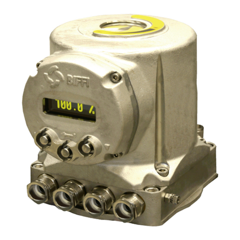
BIFFI ICON3000 Series Installation guide

Biffi ICON3000
FF2000v4 FoundationtM Fieldbus Module
Installation, Operation and Maintenance Manual
MDE 255 Rev. 1
April 2021
Copyright © Biffi. The information in this document is subject to change without notice. Updated data sheets can be obtained from our website www.biffi.it or from your nearest Biffi Center:
Biffi Italia s.r.l. - Strada Biffi 165, 29017 Fiorenzuola d'Arda (PC) – Italy PH: +39 0523 944 411 – biffi_itali[email protected]

Revision Details
Rev. Date Description Prepared Checked Approved
1 April 2021 General update (Migration to new template)
0 April 2014 Instruction FF interface module L. Piacenti A. Battaglia
Revision Details
April 2021
Installation, Operation and Maintenance Manual
MDE 255 Rev. 1
Revision Details
Revision Details

i
Installation, Operation and Maintenance Manual
MDE 255 Rev. 1
Table of Contents
April 2021
Table of Contents
Table of Contents
Section 1: Introduction
Introduction............................................................................................................1
Section 2: Operation and Storage
Operation and Storage ............................................................................................2
Section 3: Communication Features
Communication Features.........................................................................................3
Section 4: FF2000v4 rev. 3 Module
4.1 On Board Indications..................................................................................... 4
Section 5: Foundation™ Fieldbus Overview
5.1 Foundation Fieldbus Technology ..................................................................... 6
5.1.1 Physical Layer ..................................................................................... 6
5.1.2 Communication Stack ........................................................................ 7
5.1.3 User Application Layer - Blocks ........................................................... 7
5.2 Fieldbus Topology and Wiring ....................................................................... 9
5.2.1 Cable Selection ................................................................................ 10
5.3 Terminators ................................................................................................ 10
5.4 Shielding..................................................................................................... 11
5.5 Link Master Capabilities............................................................................... 11
5.6 Field Diagnostic Profile................................................................................ 12
5.7 Device Replacement.................................................................................... 15
Section 6: Function Blocks Description
6.1 Function Block: DO ..................................................................................... 16
6.1.1 DO Channels .................................................................................... 17
6.1.2 Discrete Output Channel Interlocks .................................................. 18
6.2 Function Block: DI ....................................................................................... 19
6.2.1 DI Channels ...................................................................................... 20
6.3 Function Block: AO...................................................................................... 22
6.3.1 AO Channel ...................................................................................... 22
6.4 Function Block: AI ....................................................................................... 23
6.4.1 AI Channels ...................................................................................... 24
6.5 Function Block: PID ..................................................................................... 24

ii
Table of Contents
April 2021
Installation, Operation and Maintenance Manual
MDE 255 Rev. 1
Table of Contents
Section 7: Resource Block
7.1 Transducer Blocks ....................................................................................... 35
7.1.1 Input Output Transducer Block......................................................... 36
7.1.2 Configuration Transducer Block........................................................ 41
7.1.3 Maintenance Transducer Block ......................................................... 45
Section 8: Configuration via Local Operator Interface of
FF2000v4 rev. 3
8.1 Bus Control ................................................................................................. 53
8.1.1 DIN 1 - DIN 2 .................................................................................... 53
8.1.2 Simulation........................................................................................ 54
8.1.3 Date Syncro...................................................................................... 54
8.1.4 Blank Node....................................................................................... 55
8.1.5 Reset Node....................................................................................... 55
8.2 Positioner Function ..................................................................................... 56
8.3 Fail Safe Function ........................................................................................ 57
8.4 Viewing Transmission Information .............................................................. 57
8.5 Bus Signal Failure Indication ........................................................................ 58
Section 9: ADDENDUM for Base Card FW 7.00
9.1 Multiple Functionality of ESD Command and Status .................................... 59
9.2 Multiple Functionality of Interlock Command.............................................. 60

Installation, Operation and Maintenance Manual
MDE 255 Rev. 1 April 2021
Introduction 1
Section 1: Introduction
Section 1: Introduction
The FF2000v4 rev. 3 is an electronic module that allows to connect the Biffi electrical actuator
ICON3000 to a Foundation™ Fieldbus serial communication line. The module has its microprocessor
and it is controlled by a program stored internally, it works as a pure bus interface and does not affect
the actuator control integrity.
It is installed inside the actuator housing and the communication interface is powered directly from
the fieldbus. The data lines are fully isolated from the actuator electronics.

April 2021
Installation, Operation and Maintenance Manual
MDE 255 Rev. 1
Operation and Storage
2
Section 2: Operation and Storage
Section 2: Operation and Storage
The module is designed to work and to be stored in the same environment of the actuator.

Installation, Operation and Maintenance Manual
MDE 255 Rev. 1 April 2021
Communication Features 3
Section 3: Communication Features
Section 3: Communication Features
Communication protocol: Foundation™ Fieldbus
Electrical interface: IEC 61158-2, 2 wire communication
Bus type: H1 communication bus, Voltage Mode signalling
Data rate: 31.25 kbit/second
Transmission medium: 18 AWG shielded, twisted pair as specified in the IEC / ISA
Physical Layer Standard, Clause 22.7
Topology: Bus or tree structure
Device number: 32 devices per segment
Addressing capability: Up to 240
Bus length: 1,900 m per segment
Electrical power: Bus powered
Max. voltage 32 V
Min. voltage 9 V
Rated current In= 19 mA
Fault current Imax = 24 mA
Device capacitance: < 5 nF
Device inductance: Negligible
Temperature: -40 °C, +85 °C
EMC protections: Burst. EN 61000-4-4:1995 + A1:2001 + A2:2001
Electromagnetic compatibility (EMC)
Part 4 - 4: Testing and measuring techniques
Electrical fast transient/burst immunity test
Surge: EN 61000-4-5:1995 + A1:2001
Electromagnetic compatibility (EMC)
Part 4 - 5: Testing and measuring techniques -
Surge immunity test
Device type: Link Master or Basic Device
Field diagnostic: FD_VER 1.0
Device replacement: COMPATIBILTY_REV. 2
ITK version: 6.1.1

April 2021
Installation, Operation and Maintenance Manual
MDE 255 Rev. 1
FF2000v4 rev. 3 Module4
Section 4: FF2000v4 rev. 3 Module
Section 4: FF2000v4 rev. 3 Module
The module consists in a single PCB that is installed inside the actuator housing. It is connected to the
ICON3000 base card via strip connector.
The internal wiring connects the Foundation™ Fieldbus data lines to the actuator terminal board.
Figure 1
4.1 On Board Indications
Four LEDs are mounted on the FF2000v4 rev. 3 to give the following indications for the field service.
LEDs indicators are active only when jumper JP1 is closed. There is also the SW1 switch button that
performs a reset of the FF2000v4 rev. 3 card.
DL4 (red) Base comm: BLINK or ON: when the communication between the base card
and the interface is not working properly.
OFF: when the communication between the base card and the
interface is working properly.
DL3 (red) Data area empty: ON: when Data Area on interface card is not yet loaded.
BLINK: when Data Area is being read from base card.
OFF: when Data Area is completely loaded.
DL2 (green) FF module comm: BLINK: The communication between the interface card and FF bus
module is working properly.
OFF or ON: The communication between the interface card
and FF bus module is not working properly.
DL1 (green) Power: ON: when the FF2000v4 rev. 3 is correctly powered from the main
power supply.
OFF: when the FF2000v4 rev. 3 is not powered from the main
power supply.
SW1 DL4 DL3 DL2 DL1 JP1

Installation, Operation and Maintenance Manual
MDE 255 Rev. 1 April 2021
Foundation™ Fieldbus Overview 5
Section 5: Foundation™ Fieldbus Overview
Section 5: Foundation™ Fieldbus Overview
Foundation Fieldbus is an open networking standard which provides an open specification for both the
control application and the communication on the bus.
Foundation Fieldbus communication protocol is an industry proven international standard
(IEC 61158-2) designed for use in the process industry and also complies with the ISA-SP50
recommendation for fieldbus devices.
The major benefits in adopting this standard includes:
• Multi-drop capability with up to 32 devices per segment;
• Extended trunk length using repeaters which increase the total bus length and the number
of devices in the network;
• Power and communications over the same shielded twisted pair network that allow to know
the physical status of ICON3000 actuator even if it is without actuator mains power;
• Distribution of the control into the field devices reducing the amount of control equipment
in the plant.
This last item is one of the more advantages of Foundation Fieldbus which uses standards ‘Function
Blocks’ and Device Descriptions to implement control strategy. Function Blocks are standardized
automation functions with defined behaviour used to represent different type of functions such
as discrete input (DI), discrete output (DO), analog input (AI), analog output (AO), Proportional /
Integral / Derivative (PID), etc.
Furthermore, every Foundation Fieldbus device has a Resource Block and at least a Transducer Block.
Once the hardware of a Foundation Fieldbus device is configured, fieldbus communication is used to
configure the transducer block parameters. The desired transducer functionality is associated with a
specific function block via a Channel.
The host system is used to link the function blocks together to create a control application that can
be downloaded to the devices in the segment.
More information about Foundation Fieldbus are in the documents:
• Foundation Fieldbus – Technical Overview
• Foundation Fieldbus – Wiring and installation 31.25 kbit/second, Voltage Mode,
Wire Medium Application Guide
Available at the website http://www.fieldbus.org

April 2021
Installation, Operation and Maintenance Manual
MDE 255 Rev. 1
Foundation™ Fieldbus Overview6
Section 5: Foundation™ Fieldbus Overview
5.1 FoundationtM Fieldbus Technology
Foundation Fieldbus technology consists of:
• Physical Layer
• Communication “Stack”
• User Application
The Open System Interconnect (OSI) layered communication model is used to model these
components as shows in the following Figure:
Figure 2
The Physical Layer and the Data Link Layer correspond respectively to OSI layer 1 and layer 2.
The Communication Stack is comprised of OSI layers 2 and 7; the fieldbus protocol does not use OSI
layers 3, 4, 5 and 6.
The User Application is not defined by the OSI model. Fieldbus Foundation has specified a User
Application model that Biffi has applied for FF2000v4 rev. 3 interface.
5.1.1 Physical Layer
FF2000v4 rev. 3 implements the Physical layer standards H1 that Foundation Fieldbus defines for
field device connections. The bus communication is fixed at 31.25 kbit/second, the devices can be
powered directly from the fieldbus and operate on wiring previously used for 4 - 20 mA devices.
FF2000v4 rev. 3 module is a bus powered interface: it will continue to communicate to the other
devices in the segment even if the actuator is powered off.
H1 fieldbus also supports intrinsically safe (I.S.) applications: in this case the appropriate barriers will
be used.
Biffi electrical actuators ICON3000 and are certified explosion proof and do not require an
intrinsically safe network. To preserve hazardous area protection armoured cables or conduits
will be used.
APPLICATION LAYER 7 APPLICATION LAYER
COMMUNICATION
"STACK"
PRESENTATION LAYER 6
SESSION LAYER 5
TRANSPORT LAYER 4
NETWORK LAYER 3
DATA LINK LAYER 2 DATA LINK LAYER
PHYSICAL LAYER 1 PHYSICAL LAYER PHYSICAL LAYER
OSI model Foundation Fieldbus model
Foundation Fieldbus
USER
APPLICATION
USER
APPLICATION

Installation, Operation and Maintenance Manual
MDE 255 Rev. 1 April 2021
Foundation™ Fieldbus Overview 7
Section 5: Foundation™ Fieldbus Overview
5.1.2 Communication Stack
Two types of devices are defined in the Data Link Layer specification: Basic Device and Link Master.
FF2000v4 rev. 3 module acts both type, Basic Device or Link Master.
5.1.3 User Application Layer - Blocks
The Fieldbus Foundation™ has defined a standard User Application based on ‘Blocks’. Blocks are
representations of different types of application functions.
Figure 3
The following Function Blocks are implemented in the FF2000v4 rev. 3 module:
Discrete Output (DO) 8 blocks for commands to the actuator
Discrete Input (DI) 6 blocks for data coming from the actuator
Analog Output (AO) 1 block for set-point in inching service
Analog Input (AI) 2 blocks for analog data from the actuator
PID 1 block
Transducer Blocks 1 Input Output Transducer Block,
1 Configuration Transducer Block,
1 Maintenance Transducer Block
Resource Block 1 block
USER
RESOURCE
BLOCK
TRANSDUCER FUNCTION
BLOCK

April 2021
Installation, Operation and Maintenance Manual
MDE 255 Rev. 1
Foundation™ Fieldbus Overview8
Section 5: Foundation™ Fieldbus Overview
The following Figure shows the blocks contained in the FF2000v4 module as seen by NI-FBUS,
National Instruments configuration tool:
Figure 4
The characteristics of fieldbus devices are described by the Device Description (DD) and the
Capability File (CF) that provides an extended description of each data from the device. From the CF
file is possible achieve information about the execution time of each function block.
The blocks in the FF2000v4 rev. 3 module have the following execution time:
Table 1.
Bock Type Execution Time
Discrete Output (DO) 30 milliseconds
Discrete Input (DI) 20 milliseconds
Analog Output (AO) 30 milliseconds
Analog Input (AI) 30 milliseconds
PID 40 milliseconds
Maintenance Transducer Not Applicable
Configuration Transducer Not Applicable
Input_output Transducer Not Applicable
Resource Not Applicable

Installation, Operation and Maintenance Manual
MDE 255 Rev. 1 April 2021
Foundation™ Fieldbus Overview 9
Section 5: Foundation™ Fieldbus Overview
5.2 Fieldbus Topology and Wiring
General structures of H1 networks are shown in the following Figure:
Figure 5
An appropriate termination conditioning network (terminators) must be placed at the beginning
and at the end of each segment. A suitable power supply has to be added in the segments where bus
power devices are connected.
The following Table shows the types of cables indicated by IEC / ISA Physical Layer Standard.
Table 2.
Type Description Size Max Length
Type A Shielded, twisted pair 18 AWG 1,900 m
Type B Multi twisted pair with shield 22 AWG 1,200 m
The total length of the H1 fieldbus is determined by several factors as the cable type, I.S. option and
also the total spurs length has to be considered in the total fieldbus length.
Furthermore, it is also necessary to grant to each bus powered device the minimum requested
voltage to work properly since the cable length will cause a voltage drop over the line.
The FF2000v4 rev. 3 module is a bus powered device and it will work with the following
electrical parameters:
Voltage supply: minimum 9 V DC
maximum 32 V DC
Current drain: nominal 19 mA
maximum (fault) 24 mA
Point to Point Daisy Chain Bus with spurs Tree
Fieldbus I/O
segments
spurs Junction
Box

V0= 24 V DC
L2= 200 m
V1= 20.5 V DC V2= 20.5 V DC V3= 19.9 V DC V4= 19.9 V DC
V5= 19.9 V DC
V6= 19.9 V DC
Fieldbus I/O
Fieldbus Power Supply
H1 segments
L1= 800 m
April 2021
Installation, Operation and Maintenance Manual
MDE 255 Rev. 1
Foundation™ Fieldbus Overview10
Section 5: Foundation™ Fieldbus Overview
NOTICE
Each spur has been considered 3 m long.
As shown in the Figure, the current drawn by the actuators cause a voltage drop of 5.8 V on the
Section L1and a voltage drop of 0.9 V on the Section L2.
5.2.1 Cable Selection
The preferred cable is specified in the IEC / ISA Physical Layer Standard, Clause 22.7.2 for conformance
testing and it is referred to as “Type A” fieldbus cable.
Belden 3076F is a “Type A” fieldbus cable. The following Table shows the electrical characteristics:
Table 3.
Belden 3076F
Description 18 AWG (7x26) Tinned Copper conductor, Polyethylene
insulation, Aluminium Foil-Polyester Tape (Beldfoil) shield
Shielding 100% shield coverage
Size 18 AWG (0.78 mm2)
Nominal Resistance 24 Ω/km @ 25 °C
Nominal Mutual Capacitance 78.7 pF/m @ 1 KHz
Nominal Impedance 100 Ω @ 31.25 KHz
Temperature rating -40 to +105 °C
5.3 Terminators
Each segment must be properly connected to a termination conditioning network (terminators)
placed at the beginning and at the end of each segment.
The terminators prevent distortion and signal loss and are typically purchased and installed as a
pre-assembled sealed module.
The actuator is not equipped with termination facilities.
The following Figure shows an H1 segment where 6 actuators are connected in a tree structure;
the example highlight the voltage at each device:
Figure 6

Installation, Operation and Maintenance Manual
MDE 255 Rev. 1 April 2021
Foundation™ Fieldbus Overview 11
Section 5: Foundation™ Fieldbus Overview
5.4 Shielding
When using shielded cable, connect each spur’s shield to the trunk shield and connect the overall
shield to ground at one point. Do not connect the spur’s shield in to the actuator ground.
Figure 7
5.5 Link Master Capabilities
FF2000v4 rev. 3 has Link Master (LM) capabilities; It contains Link Active Scheduler (LAS)
functionality, that can control communications on H1 fieldbus Link.
The LAS schedules and controls the segment communication. There must be at least one LM on an
H1 Link; one of those LM devices will be elected to serve as LAS. In a redundant system containing
multiple Link Masters, one of the Link Masters will become the LAS if the active LAS fails.
The LM functionality could be enabled or disabled by the configuration utility.
Figure 8
FoundationtM
Fieldbus
Interface
FD = Field Device

April 2021
Installation, Operation and Maintenance Manual
MDE 255 Rev. 1
Foundation™ Fieldbus Overview12
Section 5: Foundation™ Fieldbus Overview
5.6 Field Diagnostic Profile
The FF2000v4 rev. 3 interface, implements FF-912 Field Diagnostic Profile specification. It is
implemented by a specific parameter group of Resource Block. The diagnostics are divided into four
categories: Failure, Out of specification, Maintenance and Check Function - consistent with NAMUR
NE-107. Each of these categories share 32 conditions. Each condition can be mapped or unmapped
for each category by selecting the appropriate bit in FD_*_MAP parameter. If a condition is mapped,
then it is indicated in the parameter FD_*_ACTIVE. If the condition in FD_*_ACTIVE parameter is
not masked the corresponding bit in parameter FD_*_MASK, then the condition will be queued for
transmission using the corresponding FD_*_ALM parameter associated with the priority indicated by
the parameter FD_*_PRI.
The four categories of conditions are defined below.
Table 4.
Maintenance Although the output signal is valid, the wear reserve is nearly exhausted or a function will
soon be restricted due to operational conditions e.g. build-up of deposits.
Off-Specification
Off-specification means that the device is operating outside its specified range or an internal
diagnostic indicates deviations from measured or set values due to internal problems in the
device or process characteristics (e.g. bubble formation in flow metering or valve sticking).
Check Function Output signal temporarily invalid (e.g. frozen) due to on-going work on the device.
Failed Output signal invalid due to malfunction in the field device or its peripherals.
With the FD_*_ACTIVE parameters you know the result after the filtering by FD_*_MAP. Prior to
filtering by FD_*_MAP, the detected conditions may be observed in the FD_Simulate.Diagnostic_Value.
The complete list and functionality of Field Diagnostic parameters implemented in FF2000v4 rev. 3
interface is reported on the Resource Block paragraph. All the parameter related to Field diagnostic
are prefixed with FD_.
In Table below are listed all the conditions handled by FF2000v4 rev. 3 with respectively manufacturer
default mapping and Recommended Action.
Table 5.
FC CONDITIONS TABLE
BIT CONDITION
FAILURE-F
OFF-SPECIFICATION-S
CHECK FUNCTION-C
MAINTENANCE-M
DESCRIPTION RECOMMENDED ACTION
31 MAIN_POWER_SUPPLY x
Indicates whether device has
lost a power supply, or in case
of fault of one of the phases
that supply the actuator
transformer, or main voltage
lower than -20% or higher
than+20% of the value stated in
the nameplate menu.
Indicates whether device has
lost a power supply, or in case
of fault of one of the phases
that supply the actuator
transformer, or main voltage
lower than -20% or higher
than+20% of the value stated
in the nameplate menu.
30 SPEED_SENSOR x Measure of motor speed
not valid. Replace speed sensor
29 POSIT_SENSOR x Value of the actuator position
not valid.
Replace position sensor or
recalibrate both stroke limits.
28 HI_HI_LO_LO_INT_TEMP x
Temperature inside the
actuator enclosure higher than
90 °C or lower than -40 °C
Ambient temperature too
high or too low. Verify
insulation among actuator
and heat source

Installation, Operation and Maintenance Manual
MDE 255 Rev. 1 April 2021
Foundation™ Fieldbus Overview 13
Section 5: Foundation™ Fieldbus Overview
FC CONDITIONS TABLE
BIT CONDITION
FAILURE-F
OFF-SPECIFICATION-S
CHECK FUNCTION-C
MAINTENANCE-M
DESCRIPTION RECOMMENDED ACTION
27 HW_ERROR x
The diagnostic program
detects some malfunction in
the electronics controlling
the actuator.
Some circuit is damaged
and does not work (Call Biffi
After-sales service to solve
the problem).
26 CONFIG_ERROR x
The checksum of the EEPROM
memory that contains the
configuration data is wrong.
Reconfigure all parameters
(See details next page).
25 BASE_COM_FAIL x
The communication
between Interface card and
motherboard card is lost.
Check the main power
supply, or replace the
Hardware
(Base card and Interface
card).
24 MOT_THERMOST x
Motor thermostat open for
high temperature in the
motor windings.
Wait until the motor
cools down.
23 CONTACTOR x
The test routine reports a
failure of contactor (coil or
auxiliary contact).
Check the contactor.
22 MID_TRAV_AL x
The valve does not move in
presence of an open or
close control.
Check status of actuator
and valve mechanical parts.
Recalibrate both stroke
limits.
21 JAMMED x
No position change after
receiving an open or
close control.
Check status of actuator and
valve mechanical parts.
20 HI_HI_TORQUE x
Measured torque greater than
the relevant value configured in
torque setup or stroke
limits routine.
Operate the actuator in
opposite direction. Check the
torque needed to operate
the valve.
19 LOW_9V_BATTERY x
The voltage of the lithium
battery is too low (only
detected if the lithium battery
is present and the relevant
parameter of the miscellaneous
routine is set to “present”).
Change lithium battery.
18 EFS_MID_TRAVEL x The position is > 4% after
ESD action.
Check reset time,
check electrical stroke limits,
check mechanical stops.
17 PST T-PST x
Time needed to change the
position of the PST TRAVEL by
the spring action out
of specification.
Check baseline values and
parameter T-PST.
16 PST T-RET x
Time to return to position
before testing out of
specification.
Check baseline values and
parameter T-RET.

April 2021
Installation, Operation and Maintenance Manual
MDE 255 Rev. 1
Foundation™ Fieldbus Overview14
Section 5: Foundation™ Fieldbus Overview
FC CONDITIONS TABLE
BIT CONDITION
FAILURE-F
OFF-SPECIFICATION-S
CHECK FUNCTION-C
MAINTENANCE-M
DESCRIPTION RECOMMENDED ACTION
15 PST OV-TR x Position change greater than
allowable.
Check PST travel and
parameter OV-TR.
14 PST_ABORTED x PST cycle aborted due to
external condition.
Check if condition to abort
has happened.
13 HI_LO_MAINS x
Value of the main voltage out
of the correct range (-15% or
+10% of the value stated in the
nameplate menu) or wrong
frequency.
Check section of wires
and values of voltage and
frequency.
12 WRONG_LIMITS x
The routine that monitors the
stroke limits detects a wrong
end of travel condition.
Recalibrate both stroke
limits.
11 HI_TORQUE x
Measured torque 10% lower
than the relevant value
configured in torque setup or
stroke limits routines.
Check the torque necessary
to move the valve.
10 MAX_CYCLES_CONTACT x Maximum number of contactor
cycles reached.
Change contactor and reset
operation log.
9 HI_LO_INT_TEMP x
Temperature inside the actuator
enclosure higher than 80 °C or
lower than -35 °C.
Find the heat source and
insulate the actuator.
8 MOTOR_CUR x Motor current greater or lower
than limits. Check electrical motor.
7 MAINTEN_REQ x Date of the next maintenance
reached.
Perform maintenance and set
next maintenance date.
6 MANUAL_OPER x
The actuator is changing the
position without electrical
command.
Operator is changing the
actuator position
by handwheel.
5 ESD_ON x ESD command active
(hardwired or from FF).
Check and remove the ESD
condition (C4 pin of terminal
board or FF ESD command).
4 INTERLOCK_ON x Interlock open or close active
(hardwired or from FF).
Check the Interlock condition
(B4 and B5 pin of terminal
board or FF Interlock
command).
3 LOC_STOP_ON x Local stop button pressed. Release the Local Stop
button.
2 REM_HARDWIRED_OPER x Local selector in remote with
manual mode enabled.
Check B/HW (C8 connection
on terminal board) signal.
1 LSEL_OUT_OF_REM x Local selector not in
REMOTE position.
Switch the Local selector
to REMOTE.
0 CHECK x Check function. Allow ITK to verify operation
of Field Diagnostics.

FD_FAIL_PRI FD_OFFSPEC_PRI FD_MAINT_PRI FD_CHECK_PRI
ALARM
BROADCAST
RECORD
FD_FAIL_ALM FD_OFFSPEC_ALM FD_MAINT_ALM FD_CHECK_ALM
DS87
ALARM
BROADCAST
ENABLE
ALARM
INDICATION
(POLLING)
ALARM
DETECTION
ENABLE
FD_FAIL_MASK FD_OFFSPEC_MASK FD_MAINT_MASK FD_CHECK_MASK
FD_FAIL_ACTIVE FD_OFFSPEC_ACTIVE FD_MAINT_ACTIVE FD_CHECK_ACTIVE
FD_FAIL_MAP FD_OFFSPEC_MAP FD_MAINT_MAP FD_CHECK_MAP
Bitstring
32 bits
Bitstring
32 bits
Bitstring
32 bits
FF2000v4 rev. 3 specific conditions
3
1
3
0
2
9
2
8
2
7
2
6
2
5
2
4
2
3
2
2
2
1
2
0
1
9
1
8
1
7
1
6
1
5
1
4
1
3
1
2
1
1
1
0
0
9
0
8
0
7
0
6
0
5
0
4
0
3
0
2
0
1
0
0
Installation, Operation and Maintenance Manual
MDE 255 Rev. 1 April 2021
Foundation™ Fieldbus Overview 15
Section 5: Foundation™ Fieldbus Overview
The Figure below explains in schematic mode the functionality of Field Diagnostic.
Figure 9
5.7 Device Replacement
The FF2000v4 rev. 3 interface, implements AN-007 Device Replacement specification.
This DEV_REV 3 is a “Like Device” of previous version DEV_REV 2. It can be used as replacement of
previous FF2000v4 rev. 2 in a working plant.
The FF2000v4 rev. 3 can run the same configuration that was running in the FF2000v4 rev. 2 without
reengineering the host configuration or changing the configuration of any other element of the H1
network other than the new device.
The host system is informed by the backward compatibility with older DEV_REV 2 of FF2000v4
by COMPATIBILITY_REV parameter in Resource Block. For more detail about Device replacement
specification, check the FoundationtM Fieldbus literature.

April 2021
Installation, Operation and Maintenance Manual
MDE 255 Rev. 1
Function Blocks Description16
Section 6: Function Blocks Description
Section 6: Function Blocks Description
6.1 Function Block: DO
A Discrete Output block converts the value received across the fieldbus to something useful to the
hardware in the device. In the FF2000v4 rev. 3, there are 8 available DO Function Blocks.
Figure 10
Each DO may be connected by means of any FoundationtM Fieldbus Configuration Tool to one of the
related channels defined in the paragraph “DO Channels”.
Figure 11
Other manuals for ICON3000 Series
10
Table of contents
Other BIFFI Control Unit manuals
Popular Control Unit manuals by other brands
Giacomini
Giacomini HDB Series instructions
Huawei
Huawei SmartAX MA5612 Maintenance Guide

LEGRAND
LEGRAND IC5010 Instruction/installation sheet
Wilo
Wilo Yonos MAXO Series Installation and operating instructions

Eclipse
Eclipse BoilerMag Installation and servicing instructions

Agilent Technologies
Agilent Technologies 1100 Series user guide
