DF ROBOT TEL0051 User manual

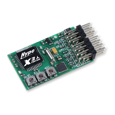
GPS/GPRS/GSM Module V3.0 (SKU:TEL0051)
From Robot Wiki
Contents
1 Introduction
2 Specification
3 Pin Out
4 Tutorial
4.1 How to drive the GSM
Mode via USB port
4.1.1 GSM mode &
GPS mode Selection
4.1.2 Network
indication
4.1.3 How to Send a
message
4.1.4 Ways to send
Ctrl +Z in Coolterm
4.1.5 How to Make a
phone call
4.2 How to drive the GPS
Mode via USB port
4.3 How to drive the GSM Mode via Arduino board
4.3.1 How to Send a message
4.3.2 How to Control your Arduino via SMS
4.3.3 How to Make a phone call
4.4 How to drive the GPS Mode via Arduino board
5 GPS Sample Code
6 Trouble shooting
7 Version history
Introduction
This is a GPS/GPRS/GSM shield from DFRobot. This shield with a Quad-band GSM/GPRS engine works on
frequencies EGSM 900MHz/DCS 1800MHz and GSM850 MHz/PCS 1900MHz. It also supports GPS
technology for satellite navigation. It's possible for your robot and control system to send messages and use the
GSM network.

It is controlled via AT commands(GSM07.07 ,07.05 and SIMCOM enhanced AT Commands). And the design of
this shield allows you to drive the GSM & GPS function directly with the computer and the Arduino Board. It
includes a high-gain SMD antenna for GPS & GSM.
This GPS/GPRS/GSM shield uses an embedded SIM908 chip from SIMCom.Featuring an industry-standard
interface and GPS function, the combination of both technologies allows goods, vehicles and people to be tracked
seamlessly at any location and anytime with signal coverage.
Specification
Power supply: 6-12v
Low power consumption (100mA@7v - GSM mode)
Quad-Band 850/900/1800/1900MHz
GPRS multi-slot class 10
Support GPS technology for satellite navigation
Embeded high-gain SMD antennas for GPS & GSM
Directly support 4*4 button pad
USB/Arduino control switch
Board Surface:Immersion Gold
Size: 81x70mm
Pin Out

NOTE: Two jumper caps of GPS/GSM UART SELECTION have been changed to a switch."Take off the jumper caps" do the same function of
"slid the switch in the middle".
More details about switches:
Switch S1: PC upload program to
Arduino board/PC communicates
with GPS/GPRS/GSM Module(
Arduino programming/module
communication).
Switch S2: GPS/GPRS/GSM
Module directly connects with PC
through USB port or module
communicates with Arduino board,
which communicates with
PC(USB/Arduino serial communication).
Tutorial
Hardwares prepare:
1. Arduino Uno
2. GPS/GPRS/GSM Module V3.0
3. SIM Card
4. Earphone & Microphone
5. External power supply via the power jack
It is recommended you to supply 7~12v power via the power jack. When using the GSM mode, the module
requires an external power. But the power consumption is not high,just 200mA@7v, when calling.

Module driver pin jumpers: Applying the Module Pin Jumpers(J10-J12) will allocate Pin 3,4,5 for driving the
module. Removing the jumpers will release the above Pins, and you could connect the driver pins to the other digital
pins on your board to avoid the pin conflict.Read more (http://www.dfrobot.com/forum/index.php?
topic=17186.msg21374#msg21374)
How to drive the GSM Mode via USB port
1. If your module works, the indicator Start LED will light up, this means that the module is running correctly.
The LED marked "NET" is used to drive a network status indication LED.
2. Send the AT commands to the module by using Coolterm (http://freeware.the-meiers.org/CoolTermWin.zip)
(or use the Arduino serial monitor).
Note: If you want to program the Arduino, please disconnect the coolterm to release the communication port.
GSM mode & GPS mode Selection
Except using UART selection jumper caps, you could switch GSM and GPS function with the IO pins also. Please
remove the jumper caps connected for hardware UART selection first!
Enable GPS mode & disable GSM mode:
digitalWrite(4,LOW);//Enable GPS mode
digitalWrite(3,HIGH);//Disable GSM mode
Enable GSM mode & disable GPS mode:
digitalWrite(3,LOW);//Enable GSM mode
digitalWrite(4,HIGH);//Disable GPS mode
Network indication
State SIM908 behavior
Off SIM908 is not running
64ms On/ 800ms Off SIM908 not registered the network
64ms On/ 3,000ms Off SIM908 registered to the network
64ms On/ 300ms Off PPS GPRS communication is established

Following the steps included in the sketch below first!
?
1
2
3
4
5
6
7
8
9
10
11
12
13
14
15
16
17
18
19
20
21
22
23
24
25
26
27
28
29
30
31
32
33
34
35
// Product name: GPS/GPRS/GSM Module V3.0
// # Product SKU : TEL0051
// # Version : 0.1
// # Description:
// # The sketch for driving the gsm mode via the USB interface
// # Steps:
// # 1. Turn the S1 switch to the Prog(right side)
// # 2. Turn the S2 switch to the USB side(left side)
// # 3. Take off the GSM/GPS jumper caps from the Uart select
// # 4. Upload the sketch to the Arduino board(Make sure turn off other
Serial monitor )
// # 5. Turn the S1 switch to the comm(left side)
// # 7. RST the board
// # wiki link-
http://www.dfrobot.com/wiki/index.php/GPS/GPRS/GSM_Module_V3.0_(SKU:TEL0051)
void setup()
{
//Init the driver pins for GSM function
pinMode(3,OUTPUT);
pinMode(4,OUTPUT);
pinMode(5,OUTPUT);
//Output GSM Timing
digitalWrite(5,HIGH);
delay(1500);
digitalWrite(5,LOW);
}
void loop()
{
// Use these commands instead of the hardware switch 'UART select' in order to
enable each mode
// If you want to use both GMS and GPS. enable the required one in your code and
disable the other one for each access.
digitalWrite(3,LOW);//enable GSM TX、RX
digitalWrite(4,HIGH);//disable GPS TX、RX
}
How to Send a message

Steps:
1. Send:AT
2. Send:AT+CMGF=1 (set the message to text format)
3. Send:AT+CMGS="XXXXX" (xxxx is the number of receiver )
4. After you see ‘<’ then send the message you want to say
5. press 'ctrl+z'(If you want to cancle,you can press Esc)
NOTE: Please do some settings as Recommended settings before connection.
If you have trouble sending Ctrl+Z, please refers to Ways to send Ctrl +Z in Coolterm
Then you will see
After several seconds,the receiver will get a message from this shield
Ways to send Ctrl +Z in Coolterm
1. After typing the message text, press enter key, it will show:

'Enter' after text finished
Then, in the input area, pressing Ctrl+Z will send out the single ctrl character successfully as below:
After press Ctrl+Z
2. Ctrl characters can also be sent out in their hexadecimal format, in which form 1A is the value of Ctrl+Z:
Sending Ctrl+Z with in hexadecimal format
How to Make a phone call
Steps:
1. Send:AT
2. Send:ATDXXXXXXX;(xxxxxxx is the number of receiver,don't forget the ;)
Then you will see

After several seconds,the receiver will get a phone call from this shield
Some AT commands
ATH : Hang up the phone
ATA : Answer the phone
How to drive the GPS Mode via USB port
You should take the module outdoor, so that you can get the GPS datas
?
1
2
3
4
5
6
7
8
9
// Product name: GPS/GPRS/GSM Module V3.0
// # Product SKU : TEL0051
// # Version : 0.1
// # Description:
// # The sketch for driving the gps mode via the USB interface
// # Steps:
// # 1. Turn the S1 switch to the Prog(right side)
// # 2. Turn the S2 switch to the USB side(left side)

10
11
12
13
14
15
16
17
18
19
20
21
22
23
24
25
26
27
28
29
30
31
32
33
// # 3. Plug the GSM/GPS jumper caps to the GSM side
// # 4. Upload the sketch to the Arduino board(Make sure turn off other
Serial monitor )
// # 5. Turn the S1 switch to the comm(left side)
// # 7. RST the board until the START led is on
// # wiki link-
http://www.dfrobot.com/wiki/index.php/GPS/GPRS/GSM_Module_V3.0_(SKU:TEL0051)
void setup()
{
//Init the driver pins for GSM function
pinMode(3,OUTPUT);
pinMode(4,OUTPUT);
pinMode(5,OUTPUT);
//Output GSM Timing
digitalWrite(5,HIGH);
delay(1500);
digitalWrite(5,LOW);
}
void loop()
{
digitalWrite(3,HIGH);//disable GSM TX、RX
digitalWrite(4,HIGH);//disable GPS TX、RX
}
Steps:
1. Send:AT
2. Send:AT+CGPSIPR=9600 (set the baud rate)
3. Send:AT+CGPSPWR=1 (turn on GPS power supply)
4. Send:AT+CGPSRST=1 (reset GPS in autonomy mode)
Then you can see

For location of the data received, please refer to Location Mapping (GPRMC)
(http://www.sanav.com/gps_tracking/webtrac-4/maps/MapLocationGPRMC.aspx)
How to drive the GSM Mode via Arduino board
How to Send a message
?
1
2
3
4
5
6
7
8
9
10
11
12
// Product name: GPS/GPRS/GSM Module V3.0
// # Product SKU : TEL0051
// # Version : 0.1
// # Description:
// # The sketch for driving the gsm mode via the Arduino board
// # Steps:
// # 1. Turn the S1 switch to the Prog(right side)
// # 2. Turn the S2 switch to the Arduino side(left side)
// # 3. Take off the GSM/GPS jumper caps from the Uart select
// # 4. Upload the sketch to the Arduino board
// # 5. Turn the S1 switch to the comm(left side)

13
14
15
16
17
18
19
20
21
22
23
24
25
26
27
28
29
30
31
32
33
34
35
36
37
38
39
40
41
42
43
44
45
46
47
48
49
50
51
52
53
54
55
56
57
// # 6. Plug the jumper caps back to GSM side
// # 7. RST the board
// # wiki link-
http://www.dfrobot.com/wiki/index.php/GPS/GPRS/GSM_Module_V3.0_(SKU:TEL0051)
byte gsmDriverPin[3] = {
3,4,5};//The default digital driver pins for the GSM and GPS mode
//If you want to change the digital driver pins
//or you have a conflict with D3~D5 on Arduino board,
//you can remove the J10~J12 jumpers to reconnect other driver pins for the module!
void setup()
{
//Init the driver pins for GSM function
for(int i = 0 ; i < 3; i++){
pinMode(gsmDriverPin[i],OUTPUT);
}
digitalWrite(5,HIGH);//Output GSM Timing
delay(1500);
digitalWrite(5,LOW);
digitalWrite(3,LOW);//Enable the GSM mode
digitalWrite(4,HIGH);//Disable the GPS mode
delay(2000);
Serial.begin(9600); //set the baud rate
delay(5000);//call ready
delay(5000);
delay(5000);
}
void loop()
{
Serial.println("AT"); //Send AT command
delay(2000);
Serial.println("AT");
delay(2000);
//Send message
Serial.println("AT+CMGF=1");
delay(1000);
Serial.println("AT+CMGS=\"15800449871\"");//Change the receiver phone number
delay(1000);
Serial.print("HELLO");//the message you want to send
delay(1000);
Serial.write(26);
while(1);
}

You can see:
After several seconds,the receiver will get a message from this shield
How to Control your Arduino via SMS
Follow the forum discussion with more coding examples and options on this link Click Me!
(http://www.dfrobot.com/forum/index.php?topic=945.msg4514#msg4514)
?
1
2
3
4
5
6
7
// Product name: GPS/GPRS/GSM Module V3.0
// # Product SKU : TEL0051
// # Description:
// # The sketch for controling the GSM/GPRS/GPS module via SMS.
// # Steps:
// # 1. Turn the S1 switch to the Prog(right side)
// # 2. Turn the S2 switch to the USB side(left side)
// # 3. Plug the GSM/GPS jumper caps to the GSM side
// # 4. Upload the sketch to the Arduino board(Make sure turn off other
Serial monitor )
// # 5. Turn the S1 switch to the comm(left side)

8
9
10
11
12
13
14
15
16
17
18
19
20
21
22
23
24
25
26
27
28
29
30
31
32
33
34
35
36
37
38
39
40
41
42
43
44
45
46
47
48
49
50
51
52
// # 6. Turn the S2 switch to the Arduino(right side)
// # 7. RST the board until the START led is on(make sure you have >6V power
supply)
// # 8. Plug the long side of LED into pin 8 and short side into GND
// # 9. Start sending "LH" and "LL" to your board to turn LED on and off.
/*
* created: 2013-11-14
* by: Grey
* Version: 0.3
* Attention: if you send the wrong SMS command to the module, just need to press
RST.
* This version can't watch the module status via the serial monitor, it only
display the Arduino command.
* If you want to watch the status,use the SoftwareSerial or the board with another
serial port plese.
*/
byte gsmDriverPin[3] = {
3,4,5};//The default digital driver pins for the GSM and GPS mode
//If you want to change the digital driver pins
//or you have a conflict with D3~D5 on Arduino board,
//you can remove the J10~J12 jumpers to reconnect other driver pins for the module!
int ledpin = 8;
char inchar;
void setup()
{
//Init the driver pins for GSM function
for(int i = 0 ; i < 3; i++){
pinMode(gsmDriverPin[i],OUTPUT);
}
pinMode(ledpin,OUTPUT);
Serial.begin(9600); //set the baud rate
digitalWrite(5,HIGH); //Output GSM Timing
delay(1500);
digitalWrite(5,LOW);
digitalWrite(3,LOW); //Enable the GSM mode
digitalWrite(4,HIGH); //Disable the GPS mode
delay(2000);
delay(5000); //call ready
delay(5000);
Serial.println("AT+CMGD=1,4"); //Delete all SMS in box
}

53
54
55
56
57
58
59
60
61
62
63
64
65
66
67
68
69
70
71
72
73
74
75
76
77
78
79
80
81
82
83
84
85
86
87
88
89
90
91
92
void loop()
{
if(Serial.available()>0)
{
inchar=Serial.read();
if(inchar=='T')
{
delay(10);
inchar=Serial.read();
if (inchar=='I') //When the GSM module get
the message, it will display the sign '+CMTI "SM", 1' in the serial port
{
delay(10);
Serial.println("AT+CMGR=1"); //When Arduino read the
sign, send the "read" AT command to the module
delay(10);
}
}
else if (inchar=='L')
{
delay(10);
inchar=Serial.read();
if (inchar=='H') //Thw SMS("LH") was
display in the Serial port, and Arduino has recognize it.
{
delay(10);
digitalWrite(ledpin,HIGH); //Turn on led
delay(50);
Serial.println("AT+CMGD=1,4"); //Delete all message
delay(500);
}
if (inchar=='L') //Thw SMS("LH") was display
in the Serial port, and Arduino has recognize it.
{
delay(10);
digitalWrite(ledpin,LOW); //Turn off led
delay(50);
Serial.println("AT+CMGD=1,4"); //Delete all message
delay(500);
}
}
}
}

When you send the SMS "LH" to the module, it WILL turn led on; when you send the SMS "LL", it will be turned
off.
How to Make a phone call
?
1
2
3
4
5
6
7
8
9
10
11
12
13
14
15
16
17
18
19
20
21
22
23
24
25
26
27
28
29
30
31
32
33
34
35
36
37
38
39
// Product name: GPS/GPRS/GSM Module V3.0
// # Product SKU : TEL0051
// # Version : 0.1
// # Description:
// # The sketch for driving the gsm mode via the Arduino board
// # Steps:
// # 1. Turn the S1 switch to the Prog(right side)
// # 2. Turn the S2 switch to the Arduino side(left side)
// # 3. Take off the GSM/GPS jumper caps from the Uart select
// # 4. Upload the sketch to the Arduino board
// # 5. Turn the S1 switch to the comm(left side)
// # 6. Plug the jumper caps back to GSM side
// # 7. RST the board
// # wiki link-
http://www.dfrobot.com/wiki/index.php/GPS/GPRS/GSM_Module_V3.0_(SKU:TEL0051)
byte gsmDriverPin[3] = {
3,4,5};//The default digital driver pins for the GSM and GPS mode
//If you want to change the digital driver pins
//or you have a conflict with D3~D5 on Arduino board,
//you can remove the J10~J12 jumpers to reconnect other driver pins for the module!
void setup()
{
//Init the driver pins for GSM function
for(int i = 0 ; i < 3; i++){
pinMode(gsmDriverPin[i],OUTPUT);
}
digitalWrite(5,HIGH);//Output GSM Timing
delay(1500);
digitalWrite(5,LOW);
digitalWrite(3,LOW);//Enable the GSM mode
digitalWrite(4,HIGH);//Disable the GPS mode
delay(2000);
Serial.begin(9600); //set the baud rate
delay(5000);//call ready

40
41
42
43
44
45
46
47
48
49
50
51
52
delay(5000);
delay(5000);
}
void loop()
{
Serial.println("AT");//Send AT command
delay(2000);
Serial.println("AT");
delay(2000);
//Make a phone call
Serial.println("ATD15902808530;");//Change the receiver phone number
while(1);
}
You can see:
After several seconds,the receiver will get a phone call from this shield
How to drive the GPS Mode via Arduino board
?

1
2
3
4
5
6
7
8
9
10
11
12
13
14
15
16
17
18
19
20
21
22
23
24
25
26
27
28
29
30
31
32
33
34
35
36
37
38
39
40
41
42
43
44
// Product name: GPS/GPRS/GSM Module V3.0
// # Product SKU : TEL0051
// # Version : 0.1
// # Description:
// # The sketch for driving the gps mode via the Arduino board
// # Steps:
// # 1. Turn the S1 switch to the Prog(right side)
// # 2. Turn the S2 switch to the Arduino side(left side)
// # 3. Take off the GSM/GPS jumper caps from the Uart select
// # 4. Upload the sketch to the Arduino board
// # 5. Turn the S1 switch to the comm(left side)
// # 6. Remove the jumpers(old version) or set the UART select switch to
middle.
// # 7. RST the board
// # If you get 'inf' values, go outdoors and wait until it is connected.
// # wiki link-
http://www.dfrobot.com/wiki/index.php/GPS/GPRS/GSM_Module_V3.0_(SKU:TEL0051)
double Datatransfer(char *data_buf,char num)//convert the data to the float type
{ //*data_buf:the data
array
double temp=0.0; //the number of the right of a decimal
point
unsigned char i,j;
if(data_buf[0]=='-')
{
i=1;
//process the data array
while(data_buf[i]!='.')
temp=temp*10+(data_buf[i++]-0x30);
for(j=0;j<num;j++)
temp=temp*10+(data_buf[++i]-0x30);
//convert the int type to the float type
for(j=0;j<num;j++)
temp=temp/10;
//convert to the negative numbe
temp=0-temp;
}
else//for the positive number
{
i=0;

45
46
47
48
49
50
51
52
53
54
55
56
57
58
59
60
61
62
63
64
65
66
67
68
69
70
71
72
73
74
75
76
77
78
79
80
81
82
83
84
85
86
87
88
89
while(data_buf[i]!='.')
temp=temp*10+(data_buf[i++]-0x30);
for(j=0;j<num;j++)
temp=temp*10+(data_buf[++i]-0x30);
for(j=0;j<num;j++)
temp=temp/10 ;
}
return temp;
}
char ID()//Match the ID commands
{
char i=0;
char value[6]={
'$','G','P','G','G','A' };//match the gps protocol
char val[6]={
'0','0','0','0','0','0' };
while(1)
{
if(Serial.available())
{
val[i] = Serial.read();//get the data from the serial interface
if(val[i]==value[i]) //Match the protocol
{
i++;
if(i==6)
{
i=0;
return 1;//break out after get the command
}
}
else
i=0;
}
}
}
void comma(char num)//get ','
{
char val;
char count=0;//count the number of ','
while(1)
{

90
91
92
93
94
95
96
97
98
99
100
101
102
103
104
105
106
107
108
109
110
111
112
113
114
115
116
117
118
119
120
121
122
123
124
125
126
127
128
129
130
131
132
133
134
if(Serial.available())
{
val = Serial.read();
if(val==',')
count++;
}
if(count==num)//if the command is right, run return
return;
}
}
void UTC()//get the UTC data -- the time
{
char i;
char time[9]={
'0','0','0','0','0','0','0','0','0'
};
double t=0.0;
if( ID())//check ID
{
comma(1);//remove 1 ','
//get the datas after headers
while(1)
{
if(Serial.available())
{
time[i] = Serial.read();
i++;
}
if(i==9)
{
i=0;
t=Datatransfer(time,2);//convert data
t=t+80000.00;//convert to the chinese time GMT+8 Time zone
Serial.println(t);//Print data
return;
}
}
}
}
void latitude()//get latitude
{
char i;
char lat[10]={
Other manuals for TEL0051
1
Table of contents
Other DF ROBOT Control Unit manuals

