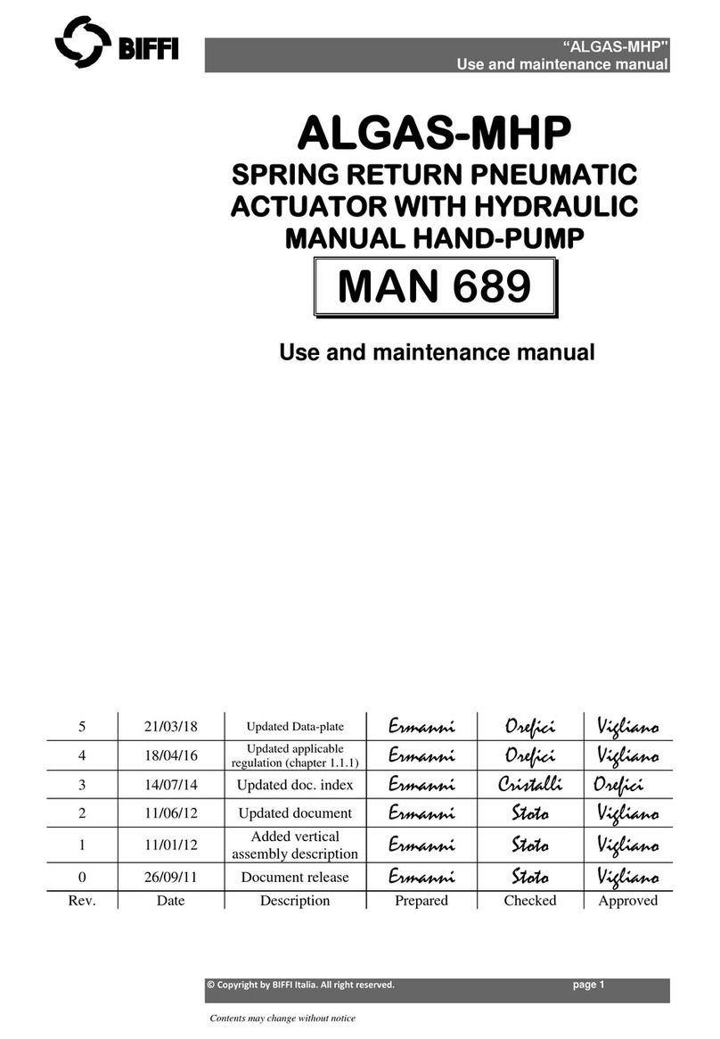
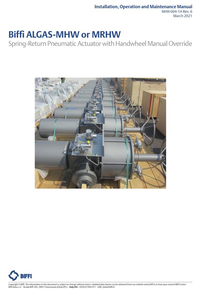
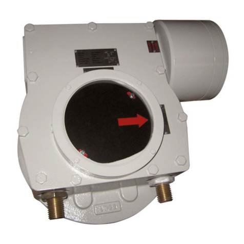
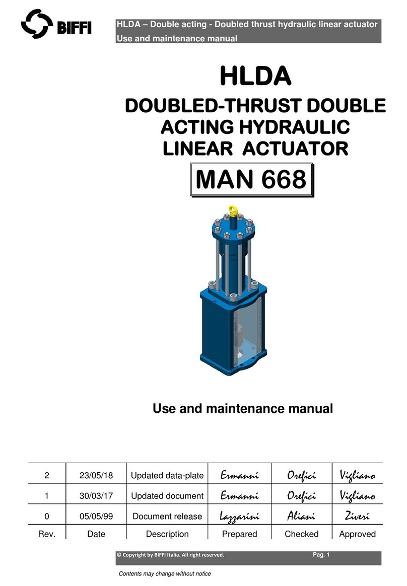
BIFFI ICON 2000 manual

2000
INSTRUCTION HANDBOOK MAN 618MAN 618
MAN 618 ICON2000


ICON2000
Electric actuator
Section 618/1
General instructions for installation
page 5
Section 618/2
Operation and configuration
page 27
Section 618/3
Maintenance and trouble-shooting
page 89
Section 618/4
Spare parts and drawings
page 103
NOTES:
BIFFI Italia has taken every care in collecting and verifying the documentation contained in this instruction and operating
manual. The information herein contained is reserved property of BIFFI Italia.
5
6
23/03/04
30/11/04
Revised document
Revised document
R. Marchelli
R. Marchelli
G. Alfieri
A. Affaticati
710/10/05 Revised document R. Marchelli A. Affaticati
811/11/05 Revised document R. Marchelli A. Affaticati
901/06/07 Revised document R. Marchelli A. Affaticati
10 15/01/11 Revised document C. Schiavi A. Affaticati
11 19/10/12 Revised document F. Campo L. Vigliano
Rev. Date Description Prepared Approved

Section 618/1
4© Copyright by BIFFI Italia. All rights reserved.
“ICON2000”
instruction and operating manual
Section 618/1

© Copyright by BIFFI Italia. All rights reserved.
Section 618/1
General instructions for installation
INDEX
CHAPTER “A”
GENERAL SAFETY INSTRUCTIONS........................................................................6
1. Range of application..........................................................................6
2. Safety instructions for installation in hazardous area.................................................6
3. Applicable standards and regulations................................................8
4. Terms and conditions.............................................................................................8
CHAPTER “B”
STORAGE AND PRE-INSTALLATION........................................................................9
1. Tests to be carried out when the actuator is received..............................................9
2. Storage procedure..................................................................................................9
3. Checks to be performed before installation............................................................11
CHAPTER “C”
INSTALLATION.......................................................................................................13
1. Working condition..............................................................................13
2. Coupling block: disassembly from the actuator.......................................................13
3. Manual operation.......................................................................................17
4. Mounting the actuator onto the valve.......................................................................18
5. Electrical connections.................................................................................20
6. Removing the terminal board enclosure......................................................20
7. Cable entries............................................................................................21
8. Terminal board.........................................................................................................22
9. Instructions for the explosion-proof enclosures....................................................23
10. Installation in environment with explosive dusts...............................................23
CHAPTER “D”
LUBRICATION.............................................................................................................25
1. Lubrication inspection.............................................................................................25
5
“ICON2000”
instruction and operating manual
Section 618/1
Section 618/1

CHAPTER
A
6© Copyright by BIFFI Italia. All rights reserved.
“ICON2000”
instruction and operating manual
Section 618/1 chapt. A
Section 618/1
GENERAL SAFETY INSTRUCTIONS
1. Range of application
ICON2000 electric actuators covered in this I&O Manual are designed for the operation of
any kind of industrial valves used in heavy industrial, chemical, petrochemical plants. Biffi will
not be liable for any possible damage resulting from use in other than the designated
applications. Such risk lies entirely with the user.
The noise emitted by the electric actuator in normal working conditions is less than 66
dB (A) with peak value 115 dB (C). Standard reference ISO 11202 (1st ed., 1995-12-15).
Warning: It is assumed that the installation, setting, commissioning,
maintenance and repair works are carried out by qualified
personnel and checked by responsible Specialists.
The electric actuators are designed in accordance with the applicable International Rules
and Specifications but the following Regulations must be observed in any case:
• the general installation and safety regulations
• the plant specific regulations and requirements
• the proper use of personal protective devices (glasses, clothing, gloves)
• the proper use of tools, lifting and transport equipment.
2. Safety instructions for installation in hazardous area
Warning: In case the electric actuator must be installed in an
HAZARDOUS AREA, as defined by the local Rules, it is
mandatory to check if the nameplate of the electric actuator
specifies the appropriate degree of protection. Maintenance
and repair works must be carried out by qualified personnel
and checked by responsible Specialists.
ICONs are designed according to IEC/EN 60079-0, IEC/EN 60079-1, IEC/EN 60079-31
standars. Different types of protection are available, depending on the marking printed on
the actuator label: Ex d IIB Txx, Ex d IIC Txx with “Explosion proof” terminal board
enclosure, or Ex d e IIB Txx, Ex d e IIB+H2 Txx, Ex d e IIC Txx with “Increased safety”
terminal board enclosure. They are suitable in hazardous area classified against the risk of
explosion for the presence of gas and dust.
Actuators have IP 66/IP 68 degree of protection according to EN 60529.

7
© Copyright by BIFFI Italia. All rights reserved. Section 618/1 chapt. A
“ICON2000”
instruction and operating manual
Section 618/1
2.1 MARKING
IECEx INE XX.ZZZZ = IECEx REFERENCE CERTIFICATE (CoC)
XX ATEX ZZZZ = ATEX REFERENCE CERTIFICATE
0080 = Notified body for ATEX quality assurance (INERIS)
II = Group II (surface industries)
2 = Category 2 apparatus
G = Explosive atmospheres caused by gas, mists or vapors
D = Explosive atmospheres caused by gas dusts
IP66/68 = Degree of protection
Hazardous zone Zone Categories according to 94/9/CE
Directive
Gas, mists or vapours 0 1G
Gas, mists or vapours 1 2G or 1G
Gas, mists or vapours 2 3G or 2G or 1G
Dust 20 1D
Dust 21 2D or 1D
Dust 22 3D or 2D or 1D
Equipment Protection Level (EPL). EN 60079-14
Explosive Atmosphere Zone EPL
Gas 0 Ga
Gas 1 Ga or Gb
Gas 2 Ga or Gb or Gc
Dust 20 Da
Dust 21 Da or Db
Dust 22 Da or Db or Dc

3. Applicable standards and regulations
EN ISO 12100-1 Safety of machinery - Basic concepts, general principles for design.
Part 1-Basic terminology, methodology.
EN ISO 12100-2 Safety of machinery - Basic concepts, general principles for design.
Part 2-Technical principles and specification.
EN 60204/1 Electrical equipment of industrial machines.
2006/42//EC Machinery Directive .
2006/95/EC Low Voltage Directive
2004/108//EC EMC Directive
94/9/EC ATEX Directive
4. Terms and conditions
Biffi guarantees each single product to be free from defects and to conform to current
goods specifications. The warranty period is one year from the date of installation by the first
user, or eighteen months from the date of shipment to the first user, whichever occurs first.
No warranty is given for products or components manufactured by third-party companies,
or for goods which have been subject to misuse, improper installation, corrosion, or which
have been modified or repaired by unauthorised personnel. Repair work due to improper
use will be charged at standard rates.
8© Copyright by BIFFI Italia. All rights reserved.
“ICON2000”
instruction and operating manual
Section 618/1 chapt. A
Section 618/1
Terminal box
Electric motor Local interface
Engagement
lever
Internal sensor
Internal gears
Handwheel

CHAPTER
B
STORAGE AND PRE-INSTALLATION
1. Tests to be carried out when the actuator is received
If the actuator is received already mounted on the valve, all operations should have already
been performed during valve/actuator assembly.
- Check that the display is active.
- Turn the handwheel until the valve is in a completely open position;
- check that the display reads 100% indicating that the valve is completely open;
- rotate the handwheel clockwise and bring the valve to a completely closed position;
- check that the display reads 0% indicating that the valve is completely closed.
If the test result is satisfactory, the actuator has already been adjusted and you can proceed
with the electrical connection.
If the actuator is delivered separately from the valve, or the above procedure shows that the
position is incorrect, all operations described in this manual must be carried out.
- Check that no damage has occurred during transport, especially to the push-buttons, the
display area glass and the selector.
- Check the information on the nameplate: serial number and performance data (nominal
torque, operation speed, protection class, motor supply voltage, etc.), and verify the
corresponding data on the display (see sect.618/2 chapt. L).
Make sure all accessories have been received with the shipment, as described in the
delivery documentation.
2. Storage procedure
Important: Not performing the following procedures will invalidate
the product guarantee.
2.1 GENERAL
The actuator leaves the factory in perfect condition, as guaranteed by an individual test
certificate. In order to maintain these characteristics until the actuator is installed on site,
proper procedures must be taken for preservation during the storage period.
BIFFI actuators are weatherproof to IP 66/IP 68. This condition can only be maintained if the
units are correctly installed/connected on site and if they have been correctly stored.
The standard plastic plugs used to close the cable entries are not weatherproof, they just
prevent the entry of undesired objects during transport.
9
© Copyright by BIFFI Italia. All rights reserved. Section 618/1 chapt. B
“ICON2000”
instruction and operating manual
Section 618/1

10 © Copyright by BIFFI Italia. All rights reserved.
“ICON2000”
instruction and operating manual
2.2 STORAGE FOR A BRIEF PERIOD (less than one year):
2.2.1 INDOOR STORAGE:
- make sure that the actuators are kept in a dry place, laid on a wooden pallet and
protected from dust.
2.2.2 OUTDOOR STORAGE:
- make sure that the actuators are protected from the direct action of weather agents
(protection by a canvas tarp or similar cover);
- place the actuators on a wooden pallet, or some other raised platform, so that they
are not in direct contact with the ground;
- if the actuators are supplied with standard plastic plugs, remove them from the cable
entries and replace them with weatherproof plugs.
2.3 LONG PERIOD STORAGE (more than one year):
2.3.1 INDOOR STORAGE:
In addition to the instructions at point 2.2.1):
- if the actuators are supplied with standard plastic plugs, replace them with weatherproof
plugs.
- In case the actuator is provided with a lithium battery, remove it and store in dry and clean
place (see Sect. 618/3 chapt. M par. 3)
2.3.2 OUTDOOR STORAGE:
In addition to point 2.2.2):
- check the general conditions of the actuator, paying particular attention to the terminal
board and local display glass.
- In case the actuator is provided with a lithium battery, remove it and store in dry and clean
place (see Sect. 618/3 chapt. M par. 3)
Section 618/1 chapt. B
Section 618/1

3. Checks to be performed before installation
- Make sure the valve to be motorised is the appropriate one for coupling to the actuator
- The electrical supply cables must be suitable for the power rating (see the test certificate
that comes with the actuator).
- Gather the right tools for the assembly and for setting the actuator controls.
If a long storage period has occurred, before reinstalling the actuator, please:
- check the status of the O-ring seals;
- check the installation of the plugs or cable glands on the cable entries;
- check whether the enclosure covers or the actuator body are cracked or broken;
- check the oil level in the actuator and top up if necessary;
- put the batteries back into place (see Sect.618/3 chapt. M par.3).
11
© Copyright by BIFFI Italia. All rights reserved.
“ICON2000”
instruction and operating manual
Section 618/1 chapt. B
Section 618/1

12 © Copyright by BIFFI Italia. All rights reserved.
“ICON2000”
instruction and operating manual
Section 618/1 chapt. B
Section 618/1

CHAPTER
C
INSTALLATION
1. Working condition
The standard actuators are suitable for the following environment temperatures:
-30°C +85°C (-22°F to +185°F)
Special versions are available for extreme environment temperatures:
-40°C +70°C (-40°F to +158°F)
-55°C +70°C (-67°F to +158°F)
Note: only for Ex d or Ex d e versions, for ambient temperature range, see the specific
attached addendum
Important: Check the "temperature environment range" embossed on
the nameplate, for the correct utilisation with respect to
the environment temperature.
2. Coupling block: disassembly from the actuator
The bushing is delivered already assembled to the drive sleeve, even when it is unmachined.
In order to perform the necessary machining, remove the bushing from its housing. Remove
the fixing screws from the coupling block.
Actuator view from the coupling side, with the block separated from the gearbox. Do not
lose the seal ring between the coupling block and the gear reduction unit.
13
© Copyright by BIFFI Italia. All rights reserved.
“ICON2000”
instruction and operating manual
Section 618/1 chapt. C
Section 618/1

14 © Copyright by BIFFI Italia. All rights reserved.
“ICON2000”
instruction and operating manual
2.1 TYPE “A” COUPLING BLOCK
2.1.1 PREPARING THE BUSHING
With a compass key, unscrew the lower ring nut.
Extract the stem nut from the block housing.
The internal thrust bearing will remain at the bottom of the block housing.
Now the bore can be machined in the stem nut to suit coupling requirements.
The same procedure is also used for possible maintenance.
Important: Before re-mounting the stem nut, make sure the
coupling tolerances to the valve stem are correct. The
threaded stem nut must be checked either with a thread
gauge or with the stem of the valve to be motorised by
screwing it all along the valve stem without excessive
friction.
Section 618/1 chapt. C
Section 618/1

15
© Copyright by BIFFI Italia. All rights reserved.
“ICON2000”
instruction and operating manual
2.1.2. RE-ASSEMBLING THE INTERNAL PARTS
It is advisable to wash the dismantled parts with a suitable solvent; dry them with
compressed air; make sure there are no metal filings or foreign bodies; spread a film of
grease on all parts (for grease type, see Sect. 618/1 chapt. D).
Proceed with the assembly of the internal parts following the reverse order of the
disassembly; tighten the lower ring nut with thread sealant LOCTITE 270 or equivalent,
making sure the stem nut still rotates freely; fix the unit to the gear reducer as described
further on.
2.2 TYPE “B1” AND “B2” COUPLING BLOCKS
2.2.1 PREPARING THE BUSHING
With a compass key, unscrew the lower ring nut.
Extract the bushing from the block housing.
The internal thrust washer will remain at the bottom of the block housing.
Now the bore can be machined in the bushing to suit coupling requirements.
The same procedure is also used for possible maintenance.
2.2.2 RE-ASSEMBLING THE INTERNAL PARTS
It is advisable to wash the dismantled parts with a suitable solvent; dry them with
compressed air; make sure that there are no metal filings or foreign bodies; spread a film of
grease on all parts (for grease type, see Sect. 618/1 chapt. D).
Proceed with the assembly of the internal parts following the reverse order of the
disassembly; tighten the lower ring nut with thread sealant LOCTITE 270 or equivalent,
making sure the bushing still rotates freely; fix the unit to the gear reducer as described
further on.
Section 618/1 chapt. C
Section 618/1

2.3 TYPE “B3” AND “B4” COUPLING BLOCKS
2.3.1 PREPARING THE BUSHING
Remove the fixing screws of the coupling flange.
Remove the flange and the bush.
Extract the bushing and machine
it according to the mating needs.
2.3.2 RE-ASSEMBLING THE INTERNAL PARTS
It is advisable to wash the dismantled parts with a suitable solvent; dry them with
compressed air; make sure there are no metal filings or foreign bodies; spread a film of
grease on all parts (for grease type see Sect. 618/1 Chap D).
Proceed with the assembly of the internal parts following the reverse order of the
disassembly. Fix the unit to the gear reducer as described further on.
2.4 FIXING THE COUPLING BLOCK TO THE GEAR REDUCTION UNIT
Check the integrity of the O-ring seal and place it in its slot on the coupling block. Make sure
the lugs of the drive sleeve fit in the correct slots on the bushing.
Fix the screws previously removed.
16 © Copyright by BIFFI Italia. All rights reserved.
“ICON2000”
instruction and operating manual
Section 618/1 chapt. C
Section 618/1
Remove the carbon steel
thrust ring.

3. Manual operation
Engagement lever locked in motor
operation position: the manual
operation cannot be engaged, and
this excludes unwanted local operations.
To engage manual operation, depress (by 20°-30°) the lever in the direction shown on the
photo. Then let the lever automatically return to its rest position. If no engagement is
obtained, slowly rotate the handwheel and repeat the operation.
Rotate the handwheel to obtain the desired operation (normally clockwise rotation to close
the valve).
A label is foreseen on the handweel with an arrow showing the closing direction (clokwise by
default). In case the closing direction is counterclockwise, the label must be removed and
re-mounted upside down.
Warning: Do not manually operate the actuator with devices other than
the handwheel and the declutch lever. Using cheater bars,
wheel wrenches, pipe wrenches, or other such devices on the
actuator handwheel or declutch lever may cause serious
personal injury and/or damage to the actuator or valve
17
© Copyright by BIFFI Italia. All rights reserved.
“ICON2000”
instruction and operating manual
Section 618/1 chapt. C
Section 618/1
Engagement lever locked in
handwheel operation position: the
operation with electric motor is
mechanically disengaged.
TO CLOSE

18 © Copyright by BIFFI Italia. All rights reserved.
“ICON2000”
instruction and operating manual
Section 618/1 chapt. C
YES NO
Section 618/1
4. Mounting the actuator onto the valve
Lubricate the valve stem.
Thoroughly clean the coupling surfaces of the valve and actuator flanges, degreasing them
carefully since torque is transmitted by friction.
Lift the actuator with slings suitable for its weight.
Size Max. weight
010 32 Kg
020 38 Kg
030 46 Kg
040 56 Kg
050 73 Kg
Warning: Never lift the valve/actuator assembly without
securing slings to both the valve and the actuator.
Warning: Never use the handwheel to lift the actuator.
The actuator will operate satisfactorily in any position. When mounted upside down, the end
of the stem cover tube should be drilled Ø5 mm to avoid build up of service fluid or
rainwater.

19
© Copyright by BIFFI Italia. All rights reserved.
“ICON2000”
instruction and operating manual
Section 618/1 chapt. C
Section 618/1
4.1 COUPLING TYPE “A”
Place the actuator vertically on the stem; screw the threaded bushing of the coupling block
on the valve stem, rotating (normally counter-clockwise) until the coupling block and flange
surfaces of the valve are securely in contact.
For safety purposes, rotate the handwheel in the opening direction for about two turns in
order to lift the valve gate from its seat to avoid (during bolt fixing) excessive axial thrusts on
the internal parts of the valve and of the actuator.
Depending on the conditions of assembly, it could be easier to separate the thrust block
from the actuator and mount it onto the valve yoke.
4.2 COUPLINGS TYPE “B1”, “B2”,”B3” AND “B4”
Check the dimensions of the valve mounting details, paying particular attention to the
protrusions of the valve stem in order to avoid any axial thrusts to the internal parts of the
actuator or the valve when the screws are tightened.
Engage the manual operation. Place the actuator vertically on the valve stem. Carry out the
coupling operations (if necessary with the help of manual operation); make sure no mating
parts are forced.
4.3 ACTUATOR FIXING
Important: In case the actuator is supplied without stud bolts and
nuts the following materials must be used as a
minimum:
- ISO class 8.8 for studs bolts and nuts
or
• ASTM A 320 Grade L7 (or L7M) for studs bolts
• ASTM A 194 Grade 4 for nuts
Model Tightening torque
010 40 Nm
020 150 Nm
030 150 Nm
040 300 Nm
050 150 Nm

© Copyright by BIFFI Italia. All rights reserved.
20
“ICON2000”
instruction and operating manual
5. Electrical connections
Before powering to the actuator check that the supply voltage details on the nameplate are
correct for the plant. Access to terminals for electrical connections and commissioning is
through the terminal cover, since all settings are non-intrusive. The removal of any other
covers without Biffi's approval will invalidate the warranty.
Biffi will not accept any responsibility for any damage or deterioration that may be caused.
Important: All the accessories (in particular cable glands) must be
certified.
As of 30 June 2003, the above accessories must carry the CE
certification conforming with 94/9/CE Directive.
5.1 PLANTS REQUIREMENTS
Protection devices (overcurrent breakers, magneto-thermal switches or fuses) should be
provided on the plant at Customer care, to protect the mains line in case of motor
overcurrent or loss of insulation between phases and earth.
6. Removing the terminal board enclosure
Using a 8mm Allen key, loosen the four screws and remove the cover.
Warning: Do not damage the mating surface of the cover.
Important: In case the screws of the cover must be replaced, a SS AISI 316
must be used with minimum yield strength of 450N/mm2
Section 618/1
Section 618/1 chapt. C
Table of contents
Other BIFFI Industrial Equipment manuals
Popular Industrial Equipment manuals by other brands

Donaldson
Donaldson X900133 installation guide

First Light
First Light C-RED One user manual
Mayr
Mayr EAS-HT 405 Series Installation and operational instructions
Spectra
Spectra DG211 user guide
deconta
deconta smart dec S 50 Original instruction manual

Keith
Keith CleenSweep Hydraulic - CSH Owner's manual & parts list
