Yale Tigrip TKG vh User manual

Mod.
TKG vh
Betriebsanleitung
Operating Instructions
D
GB
Yale Industrial
Products GmbH

Deutsch
VORWORT
Diese Betriebsanleitung ist von jedem Bedie-
ner vor der ersten Inbetriebnahme sorgfältig
zu lesen. Sie soll helfen das Produkt kennen-
zulernen und dessen bestimmungsgemässe
Einsatzmöglichkeiten zu nutzen.
Die Betriebsanleitung enthält wichtige Hin-
weise um das Produkt sicher, sachgerecht und
wirtschaftlich zu betreiben. Ihre Beachtung
hilft Gefahren zu vermeiden, Reparaturkosten
und Ausfallzeiten zu vermindern und die Zu-
verlässigkeit und Lebensdauer des Produktes
zu erhöhen. Diese Betriebsanleitung muss
ständig am Einsatzort des Produktes verfüg-
bar sein. Neben der Betriebsanleitung und den
im Verwenderland und an der Einsatzstelle
geltenden verbindlichen Regelungen zur Un-
fallverhütungsvorschrift sind auch die aner-
kannten Regeln für sicherheits- und fachge-
rechtes Arbeiten zu beachten.
BESTIMMUNGSGEMÄSSE VERWENDUNG
-Das Produkt ist für den Transport von palet-
tierten Gütern und Waren geeignet, die auf-
grund ihrer Abmessung sicher auf den
Gabelzinken gelagert werden können.
Achtung: Unbedingt Hinweise zur Verwen-
dung auf Baustellen beachten!
-Die auf dem Gerät angegebene Tragfähig-
keit (W L L) ist die maximale Last, die nicht
überschritten werden darf.
-Das Anhängen des Lastaufnahmemittels
darf nur an Hubgeräten (Krane usw.) erfol-
gen, die mit Hakensicherungen ausgestat-
tet sind. Der Haken muss sich in der Öse
frei bewegen können.
-Die angegebene Tragfähigkeit gilt bei einem
Abstand des Lastschwerpunktes von
400 mm bzw. 500 mm vom Holm (halbe
Zinkenlänge).
-Außerhalb des bodennahen Bereiches, bzw.
auf Baustellen, muss die Last durch die mit-
gelieferte straff zu spannende Sicherungs-
kette gesichert sein. Zum Befestigen der Ket-
te sind am senkrechten Holm Ösen ange-
bracht.
Seite 2
Page 3
D
GB
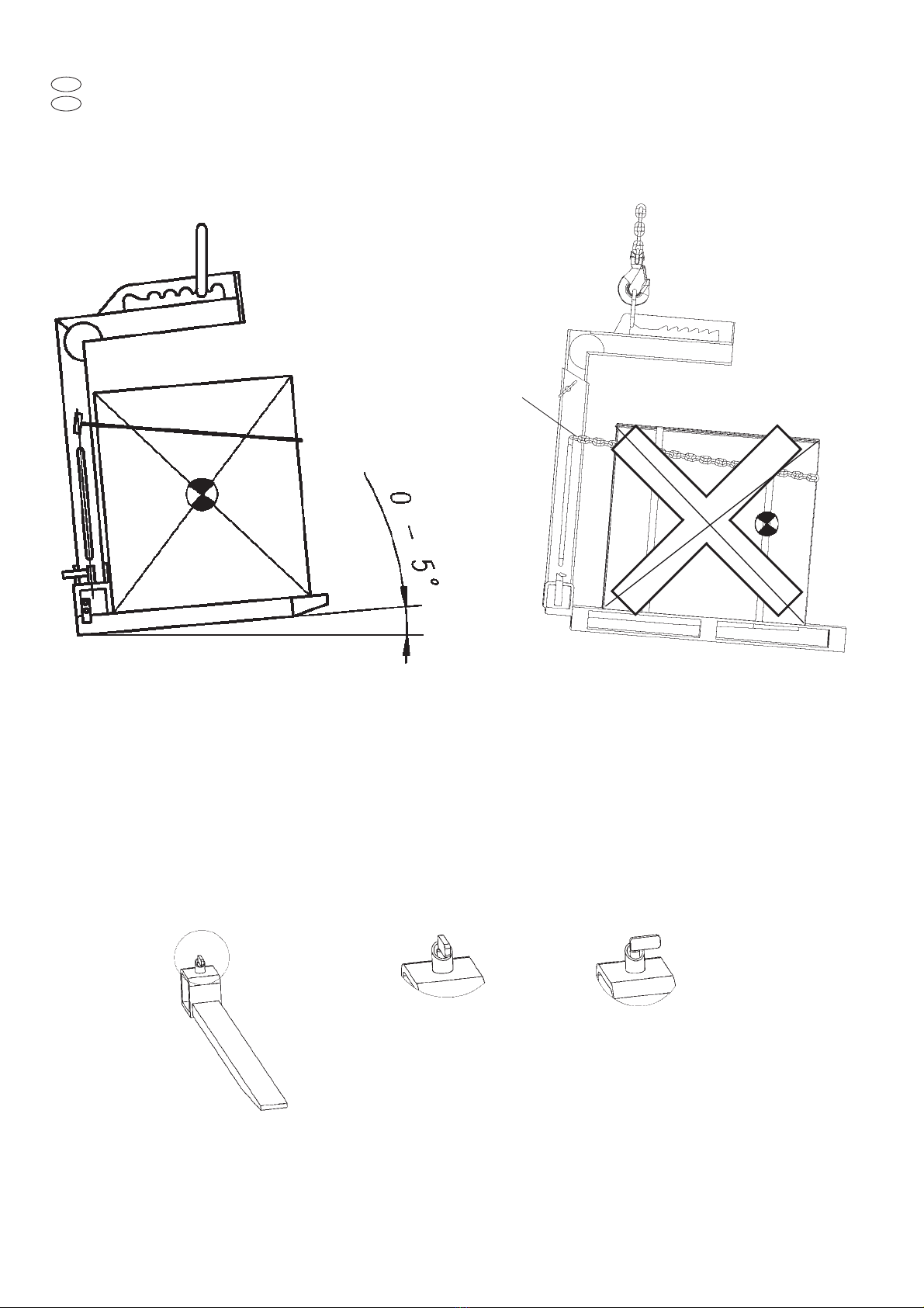
-Bei ordnungsgemäßer Positionierung der
Last und der Aufhängeöse senkrecht über
dem Lastschwerpunkt (Fig. 1) muss der Nei-
gungswinkel min. 5°nach hinten erreichen.
-Beim Transport von losen Materialien wie
z.B. Dachziegel oder Bausteinen auf Bau-
stellen muss zum Schutz vor Herabfallen
zusätzlich ein geeignetes Netz oder ein ge-
eigneter Käfig verwendet werden.
Hinweis: Die Öffnungen der Schutzeinrich-
tung muss kleiner als 50 mm2sein (siehe
Merkblatt „paketierte Steine auf Baustellen“
ZH 1/335).
-Es ist darauf zu achten, nur unbeschädigte
Paletten zu verwenden.
-Das Heben oder der Transport von Lasten
ist zu vermeiden, solange sich Personen im
Gefahrenbereich der Last befinden.
-Der Aufenthalt unter einer angehobenen Last
ist verboten.
-Lasten nicht über längere Zeit oder unbe-
aufsichtigt in angehobenem oder gespann-
tem Zustand belassen.
-Der Bediener darf eine Lastbewegung erst
dann einleiten, wenn er sich davon überzeugt
hat, dass die Last richtig angeschlagen ist.
-Beim Einhängen des Lastaufnahmemittels
ist vom Bediener darauf zu achten, dass das
Lastaufnahmemittel so bedient werden
kann, dass der Bediener weder durch das
Gerät selbst noch durch das Tragmittel oder
die Last gefährdet wird.
-Die Lastaufnahmemittel können in einer
Umgebungstemperatur zwischen –40°C
und +100°C arbeiten.
Bei Extrembedingungen sollte mit dem Her-
steller Rücksprache genommen werden.
-Die Unfallverhütungs- bzw. Sicherheits-
vorschriften für Lastaufnahmemittel des
jeweiligen Landes, in dem das Lastauf-
nahmemittel eingesetzt wird, sind unbedingt
zu beachten.
-Bei Funktionsstörungen ist das Lastauf-
nahmemittel sofort außer Betrieb zu setzen.
SACHWIDRIGE VERWENDUNG
-Die angegebene Tragfähigkeit (W LL) darf
nicht überschritten werden.
-An dem Lastaufnahmemittel dürfen keine
Veränderungen durchgeführt werden.
-Die Benutzung des Lastaufnahmemittels
zum Transport von Personen ist verboten.
-Beim Transport der Last ist eine Pendel-
bewegung und das Anstoßen an Hinder-
nisse zu vermeiden.
-Der Transport des Hebegutes sollte immer
langsam und vorsichtig durchgeführt
werden.
-Die Belastung des Lastaufnahmemittels mit
seitlichen Zugkräften ist verboten.
-Die lichte Höhe der Krangabel und die Zin-
kenlänge dürfen von dem Hebegut nicht
überschritten werden.
-Mit der Krangabel dürfen nur Güter trans-
portiert werden, die auf Paletten fest
verschnürt sind bzw. Güter die aufgrund
ihrer Form und Größe direkt von den Zinken
aufgenommen werden können.
Achtung: Beim Anheben der beladenen
Krangabel dürfen die Zinken nicht nach vorn
geneigt sein (Fig. 1).
-Lastaufnahmemittel nicht aus großer Höhe
fallen lassen.
PRÜFUNG VOR DER ERSTEN
INBETRIEBNAHME
Vor der ersten Inbetriebnahme ist das Last-
aufnahmemittel einer Prüfung durch einen
Sachkundigen zu unterziehen. Diese Prüfung
besteht im Wesentlichen aus einer Sicht- und
Funktionsprüfung. Sie sollen sicherstellen,
dass sich das Lastaufnahmemittel in einem
sicheren Zustand befindet und gegebenenfalls
Mängel bzw. Schäden festgestellt und be-
hoben werden. Als Sachkundige können z.B.
die Wartungsmonteure des Herstellers oder
Lieferanten angesehen werden. Der Unterneh-
mer kann aber auch entsprechend ausge-
bildetes Fachpersonal des eigenen Betriebes
mit der Prüfung beauftragen.
PRÜFUNG VOR ARBEITSBEGINN
-Das gesamte Lastaufnahmemittel ist auf
Beschädigungen, Risse oder Verformungen
hin zu überprüfen.
-Richtige Position der Aufhängeöse (Fig. 3)
beachten.
-Es ist darauf zu achten, dass der Absteck-
bolzen (6) am Rahmen gesichert ist.
- Die Gabelzinken müssen verriegelt sein
(Fig. 2).
-Lackbeschädigungen sind auszubessern, um
Korrosion zu vermeiden. Die Gabelzinken
sind von Schmutz, Öl, Fett und Eis beim Ein-
satz im Freien zu säubern.
-Es sind nur Kranhaken mit Hakensicherun-
gen einzusetzen.
GEBRAUCH DES
LASTAUFNAHMEMITTELS (Fig. 3)
Entsprechend der zu transportierenden Last
sind die Zinken und der Holm auf die erfor-
derliche Breite bzw. Höhe einzustellen und
durch die Verriegelung zu sichern.
D
2

English
INTRODUCTION
All users must read these operating
instructions carefully prior to the initial
operation. These instructions are intended to
acquaint the user with the lifting tackle and
enable him to use it to the full extent of its
intended capabilities. The operating in-
structions contain important information on
how to handle the lifting tackle in a safe,
correct and economic way. Acting in
accordance with these instructions helps to
avoid dangers, reduce repair cost and down
time and to increase the reliability and lifetime
of the lifting tackle. This operating instruction
must always be available for consultation in
the area where the lifting tackle is in operation.
Apart from the operating instructions and the
accident prevention act valid for the respective
country and area where the lifting tackle is
being used, also the commonly accepted
regulations for safe and professional work
must be adhered to.
CORRECT OPERATION
-The lifting tackle is suitable for the transport
of palletized goods, which on account of their
dimensions can be safely placed on the
forks.
Attention:
Instructions for the application
on building sites must be strictly adhered
to!
-The capacity indicated on the lifting tackle
is the maximum safe working load (WLL)
which must never be exceeded.
-The lifting tackle may only be attached to
hoisting devices which are provided with
safety latches. The hook must swivel freely
in the suspension lug.
-The indicated capacity applies to a distance
of 400 mm resp. 500 mm between the load
centre of gravity and the stationary base
frame (half tine length).
-Outside the immediate area of the floor, resp.
on building sites, the load must be secured
with a tight safety chain delivered with the
lifting tackle. The stationary base frame is
provided with lugs to accept the safety chain.
-With the load is properly fitted and the
suspension lug positioned vertically over the
load centre of gravity (Fig. 1), the angle of
inclination must be min 5°backwards.
-Transportation of loose materials, e.g. tiles
or bricks, on building sites must be addi-
tionally secured against falling by an ade-
quate net or cage.
Note: The openings in the protection
device must be smaller than 50 mm2.
GB
Einstellung der Gabelzinkenbreite
-Verriegelung durch Drehen öffnen.
-Zinke auf die erforderliche Breite einstellen.
-Verriegelung durch Drehen aktivieren.
Achtung: Verriegelung muss sichtbar im
Rahmen eingerastet sein (Fig. 2).
Einstellung der Höhe des Grundgestell-
Oberteils (Fig. 3)
-Sicherungsclip entfernen.
-Den Holm (2) nach oben ziehen.
-Bolzenposition wählen und Absteckbolzen
(6) einführen.
-Absteckbolzen durch Sicherungsclip sichern.
Einstellung auf den Lastschwerpunkt
-Aufhängeöse senkrecht über dem Last-
schwerpunkt positionieren und in dem ent-
sprechenden Zahnsegment halten.
-Mit dem Hebezeug langsam Anziehen und
so die Position fixieren.
-Im leeren Zustand hinterste Aufhängeösen-
position verwenden.
- Als Bediener immer neben der Krangabel
stehen und einen Sicherheitsabstand von
einer Armlänge einhalten.
-Das Zugseil oder die Zugkette des Kranes
muss immer Senkrecht über die Aufhänge-
öse stehen um eine plötzliche Lastbewegung
zu vermeiden
Achtung: Der Lastpunkt darf sich nicht über
die maximale Schwerpunktlage (Fig. 1) hin-
aus verschieben (Einstellungen beachten).
Verwendung der Sicherungskette (auf
Baustellen unbedingt erforderlich)
-Mitgelieferte Sicherungskette um das palet-
tierte Hebegut schlingen und straff ziehen.
-Kette in die vorgesehene Öse einführen und
einhängen.
Anheben bzw. Absetzen der Last
-Aufhängeöse immer senkrecht über dem
Lastschwerpunkt positionieren.
-Last langsam anheben bzw. absetzen um
ein Kippen der Last zu verhindern.
PRÜFUNG/WARTUNG
Die Prüfung ist mindestens einmal jährlich,
bei schweren Einsatzbedingungen in kürzeren
Abständen, von einem Sachkundigen vorzu-
nehmen. Die Prüfungen sind im Wesentlichen
Sicht- und Funktionsprüfungen, wobei der
Zustand von Bauteilen hinsichtlich Beschädi-
gung, Verschleiß, Korrosion oder sonstigen Ver-
änderungen beurteilt, sowie die Vollständig-
keit und Wirksamkeit der Sicherheitseinrich-
tungen festgestellt werden muss.
Reparaturen dürfen nur von Fachwerkstätten,
die Orginal TIGRIP Ersatzteile verwenden,
durchgeführt werden.
Die Instandsetzung oder der Austausch von
verschlissenen Bauteilen ist unbedingt er-
forderlich, wenn sichtbare Schäden vorliegen.
Die Prüfungen sind vom Betreiber
zu veranlassen.
3

-Make sure that the pallets used are in per-
fect condition.
-Do not lift or transport loads while person-
nel are in the danger zone.
-Do not allow personnel to pass under a sus-
pended load.
-Aload must not be suspended or left unat-
tended for a longer period of time.
-The operator may not move the load until
he in convinced that the load is correctly
attached.
-During positioning of the lifting tackle, the
operator must ensure that neither the fork,
slings or load pose a danger to himself or
other personnel.
-The lifting tackle may only be used at
ambient temperatures between – 40°C
and +100°C. For extreme temperatures
exceeding this range, please contact the
manufacturer.
-The accident prevention act and safety reg-
ulations valid in the country of operation are
to be strictly adhered to at all times.
-If defects are found, stop using the lifting
tackle immediately.
INCORRECT OPERATION
-Do not exceed the rated lifting capacity
(WLL).
-Do not tamper with lifting tackle.
-It is forbidden to use the lifting tackle for the
transport of personnel.
-When transporting loads ensure that the load
does not swing or come into contact other
objects.
-Always transport the load slowly and care-
fully.
-It is forbidden to apply side-pull forces to the
lifting tackle.
-The load may not extend beyond the clear-
ance height of the lifting tackle or the length
of the tines.
-The lifting tackle may only be used for the
transport of goods which are firmly lashed
on pallets resp. commodities, which – on
account of their shape and size – can be
picked up by the tines directly.
Attention: When lifting the loaded crane
fork, the tines must not tilt forwards (Fig. 1).
-Do not allow the lifting tackle to fall from a
great height.
INSPECTION BEFORE INITIAL
OPERATION
Each lifting tackle must be inspected prior to
initial operation by a competent person. The
inspection is visual and functional. This inspec-
tion shall establish that the unit is safe and
has not been damaged by incorrect transport
or storage. Inspections should be made by a
representative of the manufacturer or the sup-
plier although the company can assign its own
suitably trained personnel.
INSPECTIONS BEFORE STARTING
WORK
-Check the complete lifting tackle for dam-
age, cracks or deformations.
-Observe correct position of the suspension
lug (Fig. 3).
-Make sure that the socket pin (6) on the sta-
tionary frame is properly locked.
- The fork tines must be locked (Fig. 2).
-Paint damages should be repaired to pre-
vent corrosion. The tines must be free from
soiling, oil, grease and – in case of outdoor
operation - ice - Crane hooks must be pro-
vided with safety latches.
USING THE CRANE FORKS (Fig. 3)
Fork tines and base frame have to be adjusted
to the required width resp. height of the load
to be transported and locked accordingly.
Adjustment of fork width
-Open the locking mechanism by turning the
spring bolt.
-Adjust the fork tines to the required width.
-Activate the locking mechanism by turning
the spring bolt.
Attention: The locking mechanism must be
visibly engaged in the frame (Fig. 2).
Height adjustment of the movable
base frame (Fig. 3)
-Remove the safety clip.
-Pull the movable base frame (2) upwards.
-Select correct pin position and insert the
socket pin (6) accordingly.
-Secure the socket pin with the safety clip.
Adjustment to the load cent re of
gravity
Position the suspension lug vertically above
the centre of gravity and engage in the appro-
priate gear segment.
-Start lifting slowly in order to retain the posi-
tion.
-In the unloaded condition, engage the sus-
pension lug in the hindmost position.
-The operator should always stand clear at
the side of the crane forks with a safety dis-
tance of an arm length.
-The lifting rope or chain of the crane must
always be vertical over the suspension lug
of the lifting tackle in order to avoid a sud-
den load movement.
Attention: The load centre must not exceed
the max. position of the centre of gravity (Fig.
1). (Adjustments should be observed).
Using the safety chain (mandatory on
building sites)
-Loop the delivered safety chain around the
lifting product and pull tight.
Feed the safety chain through the designat-
ed lug and secure.
Lifting resp. lowering of the load
-Position the suspension lug vertically above
the load centre of gravity.
-Always lift and lower the lifting tackle slowly
in order to avoid tilting of the load.
INSPECTIONS AND SERVICE
Inspections are to be made by a competent
person at least once annually unless adverse
working conditions dictate shorter periods. The
clamp is to be inspected for damage, wear,
corrosion or other irregularities and all safety
devices have to be checked for completeness
and effectiveness.
Repairs may only be carried out by specialist
workshops that use original TIGRIP spare
parts.
In case of obvious defects or damages the
crane forks must be repaired and worn com-
ponents replaced.
Inspections are instigated by the user.
4

5
D
GB
Sachwidrige Verwendung
Incorrect operation
Fig. 1
Fig. 2
verriegelte Position
locked position
geöffnete Position
open position
Öse für
Sicherungskette
Lug for safety chain

6
Beschreibung
1Aufhängeöse
2Grundgestell Oberteil
3Grundgestell Unterteil
4Tragzinken
5Federriegel
6Absteckbolzen mit Klappstecker,
Schlüsselring und Kette
7Öse für Sicherungskette
(nicht dargestellt)
Description
1Suspension lug
2Movable base frame
3Stationary base frame
4Fork tine
5Spring pin
6Socket pin with locking device
7Lug for safety chain (not shown)
1
5
6
2
3
4
Fig. 3

7
EG Konformitätserklärung 2006/42/EG (Anhang II A)
Hiermit erklären wir, dass das nachfolgend bezeichnete Lastaufnahmemittel aufgrund seiner Konzipierung und Bauart sowie in der von uns
in Verkehr gebrachten Ausführung den einschlägigen grundlegenden Sicherheits- und Gesundheitsanforderungen der EG-Richtlinie Maschinen
entspricht.
Bei einer nicht mit uns abgestimmten Änderung des Lastaufnahmemittels verliert diese Erklärung ihre Gültigkeit. Weiterhin verliert diese EG-
Konformitätserklärung ihre Gültigkeit, wenn die Maschine nicht entsprechend den in der Betriebsanleitung aufgezeigten bestimmungsgemä-
ßen Einsatzfällen eingesetzt und die regelmäßig durchzuführenden Überprüfungen nicht ausgeführt werden.
Produkt: Lastaufnahmemittel
Typ: Krangabel TKG vh Tragfähigkeit: 1.000 kg, 1.500 kg, 2.000 kg, 3.000 kg, 5.000 kg
Serien Nr.: Seriennummernkreise für die einzelnen Tragfähigkeiten werden im Produktionsbuch festgehalten
Einschlägige EG-Richtlinien: EG-Maschinenrichtlinie 2006/42/EG
Angewandte Normen: ISO 12100; EN 349; EN 13155; BGV D6; BGR 500
Qualitätssicherung: DIN EN ISO 9001
EC Declaration of Conformity 2006/42/EC (Appendix II A)
Hereby we declare, that the construction and commercialised execution of the below Lifting Equipment complies with the essential health
and safety requirements of the EC Machinery Directive. The validity of this declaration will cease in case of any modification not being agreed
with us previously.
Furthermore, validity of this declaration will cease in case that the machine will not be operated correctly and in accordance to the operating
instructions and/or not be inspected regularly.
Product: Non-fixed load lifting attachment
Type: Crane forks TKG vh Capacity: 1.000 kg, 1.500 kg, 2.000 kg, 3.000 kg, 5.000 kg
Serial no.: Serial numbers for the individual capacities are registered in the production book
Relevant EC Directives: EC Machinery Directive 2006/42/EC
Standards in particular: ISO 12100; EN 349; EN 13155; BGV D6; BGR 500
Quality assurance: DIN EN ISO 9001
Datum/Hersteller-Unterschrift 2007- 07- 04
Date/Manufacturer‘s signature
Dipl.-Ing. Andreas Oelmann
Angaben zum Unterzeichner Leiter Qualitätswesen
Identification of the signee Manager Quality assurance
D
GB

Ident.-No.: 09900556/07. 2007
Reg. Nr. 151
Certified since November 1991
Germany and
Export territories
-European Headquarters-
Yale Industrial Products GmbH
Am Lindenkamp 31
42549 Velbert
Phone: 00 49 (0)20 51/600-0
Fax: 00 49 (0) 20 51/600-127
Web Site: www.yale.de
E-mail: [email protected]
Austria
Yale Industrial Products GmbH
Gewerbepark, Wiener Straße 132a
2511 Pfaffstätten
Phone: 00 43(0) 22 52/4 60 66-0
Fax : 00 43 (0) 22 52/4 60 66-22
Web Site: www.yale.at
E-mail: [email protected]
Netherlands
Yale Industrial Products B.V.
Grotenoord 30
3341 LT Hendrik Ido Ambacht
Phone: 00 31 (0)78/6 82 59 67
Fax : 00 31 (0)78/6825974
Web Site: www.yaletakels.nl
E-mail: information@yaletakels.nl
Hungary
Yale Industrial Products Kft.
8000 Székesfehérvár
Repülőtér
Phone: 00 36 (06) 22/546-720
Fax: 00 36 (06) 22/546-721
Web Site: www.yale.de
E-mail: [email protected]
France
Yale Levage SARL
Zone Industrielle des Forges
18108 Vierzon Cedex
Phone: 00 33 (0) 248 71 85 70
Fax : 00 33 (0)2487530 55
Web Site: www.yale-levage.com
E-mail: [email protected]
United Kingdom
Yale Industrial Products
A trading division of
Columbus McKinnon
Corporation Ltd.
Knutsford Way, Sealand Industrial Estate
Chester CH1 4NZ
Phone: 00 44 (0)1244375375
Fax : 00 44 (0)1244377403
Web Site: www.yaleproducts.com
E-mail: sales.uk@cmworks.com
Yale Industrial Products
(Northern Ireland)
A trading division of
Columbus McKinnon
Corporation Ltd.
Unit 12, Loughside Industrial Park
Dargan Crescent, Belfast BT3 9JP
Phone: 00 44 (0)28 90 7714 67
Fax : 00 44 (0)2890 7714 73
Web Site: www.yaleproducts.com
E-mail: sales.uk@cmworks.com
Italy
Columbus McKinnon Italia Srl
Via P. Picasso, 32
20025 Legnano (MI) Italy
Phone: 0039 03315763 29
Fax : 00 39 033146 8262
Web Site: www.cmworks.com
E-mail: [email protected]
Spain and Portugal
Yale Elevación Ibérica S.L.
Ctra. de la Esclusa, 21 acc. A
41011 Sevilla
Phone: 00 34 (0) 954 29 89 40
Fax : 00 34 (0)954298942
Web Site: www.yaleiberica.com
E-mail: [email protected]
South Africa
Yale Industrial Products (Pty) Ltd.
P.O. Box 15557
Westmead, 3608
Phone: 00 27(0) 31/7 00 43 88
Fax : 00 27 (0)31/7004512
Web Site: www.yale.co.za
E-mail: [email protected]
China
Yale Hangzhou
Industrial Products Co., Ltd.
Xiaoshan, Yiqiao, Zhejiang Province
Postcode 311256
Phone: 00 86 571824 09 250
Fax : 00 86 5718 24 06 211
Web Site: www.yale-cn.com
E-mail: [email protected]
Thailand
Yale Industrial Products
Asia Co., Ltd.
525 Rajuthit Road
Hat Yai, Songkhla 90110
Phone: 00 66 (0)74 25 2762
Fax : 00 66 (0) 74 36 27 80
Web Site: www.yale.de
E-mail: weeraporn@yalethai.com
Technische Änderungen vorbehalten. Keine Gewährleistung für Druckfehler oder Irrtümer – Subject to engineering changes and improvements. No warranty for printing errors or mistakes.
Reproduktionen, gleich welcher Art, nur mit schriftlicher Genehmigung der Firma Yale Industrial Products GmbH!
Reproduction of any kind, only with written authorisation of Yale Industrial Products GmbH!
Table of contents
Other Yale Forklift manuals