Bikecomm BikeComm User manual

1
User Guide

2
CONTENTS
INTRODUCTION
Please
Read
This
First
4
Quick
Start
4
Package
Contents
5
Getting
To
Know
the
Control
Box
7
Getting
To
Know
the
Helmet
Headset
8
THE
HELMET
HEADSET
Helmet
Headset
Status
Light
8
Powering
On
the
Helmet
Headset
9
Powering
Off
the
Helmet
Headset
9
Charging
the
Helmet
Headset
9
Helmet
Headset
Volume
Control
10
Helmet
Headset
Wireless
Technology
10
Installing
the
Helmet
Headset
11
Quick
Removal
of
the
Headset
Unit
12
Connecting
the
Helmet
Headsets
to
the
Control
Box
21
Connecting
the
Helmet
Headset
Rider
to
the
Control
Box
22
Connecting
the
Helmet
Headset
Passenger
to
the
Control
Box
22
THE
CONTROL
BOX
Control
Box
Status
Lights
13
Powering
On
the
Control
Box
14
Powering
Off
the
Control
Box
15
Placement
of
the
Control
Box
15
Connecting
the
Control
Box
to
Your
Battery
16
Control
Box
Volume
Setting
17
CONNECTING
YOUR
TWO
WAY
RADIO
TO
THE
CONTROL
BOX
Connecting
Your
Two
Way
Radio
to
the
Control
Box
17
Noise
Filter
Accessory
19
CONNECTING
WIRED
DEVICES
TO
THE
CONTROL
BOX
Connecting
the
Push
To
Talk
Button
20
Connecting
to
the
Control
Box
Radio
Socket
21
Connecting
to
the
Control
Box
AUX1
and
AUX2
Socket
21
Connecting
to
the
Control
Box
Audio
Socket
21
CONNECTING
WIRELESS
DEVICES
TO
THE
CONTROL
BOX
Connecting
the
Helmet
Headsets
to
the
Control
Box
21
Connecting
the
Helmet
Headset
Rider
to
the
Control
Box
22
Connecting
the
Helmet
Headset
Passenger
to
the
Control
Box
22
Connecting
to
the
Control
Box
MPR
Connection
23
Connecting
to
the
Control
Box
Other
Connection
23
Connecting
your
Garmin
zūmo
®
550
24

3
BIKERCOM
OPERATION
Connection
Priorities
25
OPERATING
RIDER
TO
PASSENGER
INTERCOM
Operating
Rider
to
Passenger
Intercom
26
Rider
to
Passenger
Intercom
Activation
Volume
26
OPERATING
BIKE
TO
BIKE
INTERCOM
Operating
Bike
to
Bike
Intercom
27
OPERATING
AUX1
AND
AUX2
WIRED
CONNECTIONS
Operating
AUX1
and
AUX2
Wired
Connections
27
OPERATING
THE
AUDIO
WIRED
CONNECTION
Operating
the
Audio
Wired
Connection
28
OPERATING
THE
MPR
WIRELESS
CONNECTION
WITH
A
MOBILE
PHONE
Operating
the
MPR
Wireless
Connection
with
a
Mobile
Phone
28
OPERATING
THE
MPR
WIRELESS
CONNECTION
WITH
A
Garmin
zūmo
®
550
Operating
the
MPR
Wireless
Connection
with
a
Garmin
zūmo
®
550
29
OPERATING
THE
OTHER
WIRELESS
CONNECTION
Operating
the
Other
Wireless
Connection
29
SPECIFICATIONS
Helmet
Headset
Specifications
30
Control
Box
Specifications
31
WARRANTY
Warranty
Terms
and
Conditions
32
Making
a
Warranty
Claim
32
CONTACT
Contact
32
NOTICES
Notices
32

4
INTRODUCTION
PLEASE READ THIS FIRST
Thank
you
for
choosing
the
BikerCom
as
your
motorcycle
communications
system;
we
know
you
have
many
choices
available
and
are
honored
you
have
put
your
trust
in
the
BikerCom
system.
The
BikerCom
has
been
designed
to
meet
all
your
motorcycle
communication
requirements
and
expectations,
if
you
have
any
comments,
questions
or
feedback
please
contact
us
at
service@openroad.com.tw
and
you
will
receive
a
prompt
reply.
Before
using
your
BikerCom
for
the
first
time
it
is
recommended
you
read
this
User
Guide
to
give
you
a
complete
overview
of
all
the
system
components
and
functionality;
once
you
are
familiar
with
the
BikerCom,
setup
and
use
should
be
convenient
and
reliable.
The
BikerCom
is
designed
to
be
used
in
conjunction
with
a
wide
range
of
communications
equipment
such
as
two
way
radios,
mobile
phones,
and
navigation
devices;
before
using
another
device
with
your
BikerCom
ensure
you
are
familiar
with
its
operation.
Whenever
riding
your
motorcycle
safety
should
be
your
first
priority.
The
BikerCom
is
designed
exclusively
for
motorcycle
enthusiasts
and
safety
was
a
constant
consideration
in
its
development.
Ultimately
it
is
the
rider’s
responsibility
to
ensure
that
their
safety
and
the
safety
of
any
passenger
is
in
no
way
compromised
by
use
of
the
BikerCom.
We
take
this
opportunity
to
wish
you
safe
and
enjoyable
motorcycling.
QUICK START
1.
Connect
the
Control
Box
to
your
motorcycle
battery.
2.
Connect
wired
devices
to
the
Control
Box.
3.
Power
On
wired
devices.
4.
Start
your
motorcycle.
5.
Power
On
the
Helmet
Headsets.
6.
Power
On
the
Control
Box.
7.
Verify
Helmet
Headset
success
connect
to
Control
Box.
8.
Connect
wireless
devices
to
the
Control
Box.
9.
Adjustment
wired
and
wireless
devices
volume.

5
PACKAGE CONTENTS
COMPONENT
DESCRIPTION
QUANTITY
IMAGE
Control
Box
(CB)
Core
of
the
1
BikerCom
System
Helmet
Headset
Unit
Helmet
Headset
Rider
(HHR,
Color:
Orange)
Helmet
Headset
Passenger
(HHP
Color:
Green)
Helmet
Headset
One
for
the
Rider
2
One
for
the
Passenger
Helmet
Headset
Clip
Attaches
to
the
Helmet
2
Boom
Microphone
Adjustable
Microphone
2
Power
Supply
Unit
For
charging
the
1
Helmet
Headsets
Helmet
Headset
Attach ment
Pads
(Hook
and
loop
fastener
type)
For
attaching
the
Helmet
Headsets
to
the
Helmet
2
sets
Speaker
Fastening
Dot
(Hook
and
loop
fastener
type)
For
fastening
the
Speakers
8
inside
the
helmet

6
COMPONENT
DESCRIPTION
QUANTITY
IMAGE
Speaker
Ear
Pocket
Spacer
Dot
For
adjusting
the
Speaker
space
10
inside
the
helmet
Power
Cable
With
Fuse
For
connecting
the
Control
Box
1
to
the
battery
Push
To
Talk
Button
(PTT)
Connection
Cable
and
adhesive
pad
For
transmitting
with
Two
Way
Radio
1
Connection
Cable
(3.5mm
Audio
Jack)
For
connecting
wired
devices
2
to
the
Control
Box
Two
Way
Radio
Connection
Cable
(L
Type)
For
connecting
the
Two
Way
Radio
1
to
the
Control
Box
Two
Way
Radio
Connection
Cable
(K
Type)
For
connecting
the
Two
Way
Radio
1
to
the
Control
Box
Extension
Cable
For
extending
the
distance
of
the
PTT
Button
and/or
1
Two
Way
Radio
Connection
Cables

User
Guide
User
Guide
1
GETTING
TO
KNOW
THE
CONTROL
BOX
Helmet
Headset
Rider
(HHR)
Helmet
Headset
Passenger
(HHP)
LEDs
to
indicate
Helmet
Headset
Connection
status
Power
Power
On
and
Off
the
Control
Box.
Mobile
Phone
Rieder
(MPR)
.
Connect
with
the
Rider’s
Bluetooth
equipped
device.
Other
Connect
with
a
Bluetooth
equipped
device
Push
To
Talk
Connect
the
Push
To
Talk
Button.
Two
Way
Radio
Connect
your
Two
Way
Radio.
Auxiliary
Connect
your
N
avigation
or
Radar
Detector
Device.
Audio
7
Connect
your
Audio
Player.
Power
Cable
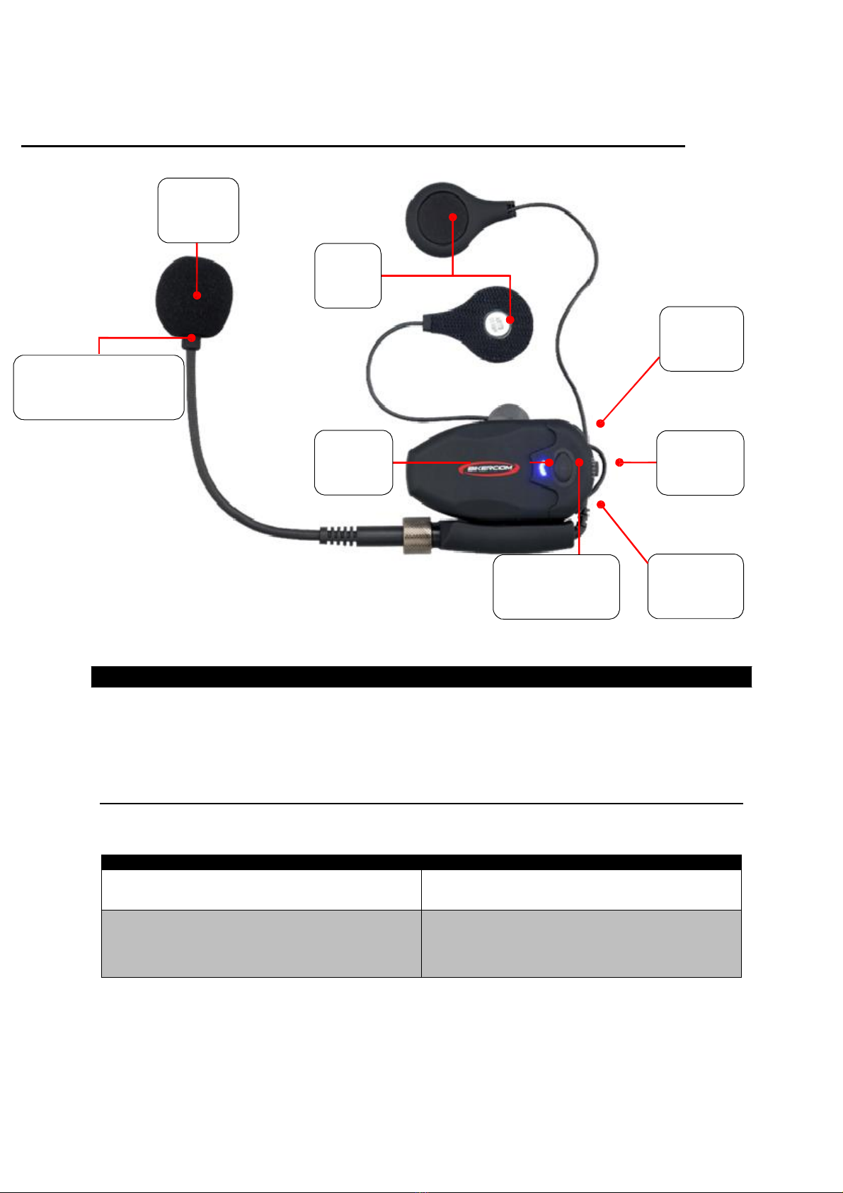
GETTING
TO
KNOW
THE
HELMET
HEADSET
Microphone
Speakers
Volume
Up
+
Microphone
Positioning
Indicator
One
strip
black,
one
strip
silver.
Status
Light
Charging
Port
Multi
Function
Button
Volume
Down
-
THE
HELMET
HEADSET
The
BikerCom
includes
two
Helmet
Headsets;
the
Helmet
Headset
Rider
(HHR,
color:
Orange)
is
for
the
Rider
and
the
Helmet
Headset
Passenger
(HHP,
color:
Green)
is
for
the
Passenger.
The
Helmet
Headsets
have
a
preset
wireless
connection
with
the
Control
Box;
you
do
not
need
to
perform
any
setup
procedure
between
the
Helmet
Headsets
and
the
Control
Box.
HELMET HEADSET STATUS LIGHT
The
Helmet
Headset
has
one
status
light
that
indicates
the
current
status
of
the
headset,
such
as
the
power
and
if
the
Headset
is
connected
to
the
Control
Box.
HELMET
HEADSET
STATUS
LIGHT
HELMET
HEADSET
STATUS
No
light
Power
Off
Mode
Steady
four
times
blinking
blue
light
Power
On
Mode
Not
connected
to
Control
Box
Not
ready
for
use
8
9
HELMET
HEADSET
STATUS
LIGHT
HELMET
HEADSET
STATUS
Steady
single
blinking
blue
light
Power
On
Mode
Connected
to
Control
Box
Ready
for
use
Steady
four
times
blinking
red
light
when
power
off
Battery
Low
Steady
four
times
blinking
green
light
when
power
off
Battery
Full
Still
red
light
Charging
Connected
to
Power
Supply
Unit
POWERING ON THE HELMET HEADSET
To
Power
On
the
Helmet
Headset
long
press
the
Multi
Function
Button
for
approximately
3
seconds;
when
Powered
On
the
status
light
will
quickly
blink
red
and
blue.
POWERING OFF THE HELMET HEADSET
To
Power
Off
the
Helmet
Headset
long
press
the
Multi
Function
Button
for
approximately
7
seconds;
the
status
light
will
quickly
blink
red
or
green
(depends
on
battery
status)
4
times
and
Power
Off.
CHARGING THE HELMET HEADSET
The
two
Helmet
Headsets
will
have
some
power
in
the
battery
however
completing
a
full
charge
is
recommended
before
their
first
use.
To
charge
the
Helmet
Headset
complete
the
following
steps:
1.
Connect
the
Power
Supply
Unit
plug
to
the
wall
socket
and
connect
the
Mini
USB
plug
to
the
Helmet
Headset
charging
socket.
2.
The
Helmet
Headset
status
light
will
display
a
still
red
light
when
charging.
3.
When
charging
is
complete
the
Helmet
Headset
status
light
will
turn
off.
NOTE:
When
the
Helmet
Headset
battery
is
low
and
requires
charging
the
status
light
will
four
blink
red
when
power
off
process;
under
normal
use
the
Helmet
Headset
battery
life
is
up
to
12
hours
talk
time
and
a
complete
charge
will
require
up
to
2.5
hours.

10
HELMET HEADSET VOLUME CONTROL
The
Helmet
Headset
Volume
can
be
adjusted
to
suit
the
preference
of
the
Rider
and/or
Passenger.
The
Helmet
Headset
must
be
connected
to
the
Control
Box
to
adjust
the
volume
level.
INCREASING THE HELMET HEADSET VOLUME
To
increase
the
Helmet
Headset
volume
complete
the
following
steps:
1.
Ensure
the
Helmet
Headset
is
in
Power
On
mode
and
connected
to
the
Control
Box.
2.
To
increase
the
volume,
press
the
Volume
Up
+
button;
the
status
light
will
flash
red
and
blue
indicating
the
volume
has
been
increased
one
level.
3.
To
increase
the
volume
another
level
repeat
the
above
step.
4.
The
maximum
Helmet
Headset
volume
level
has
been
achieved
when
the
status
light
displays
a
still
red.
DECREASING THE HELMET HEADSET VOLUME
To
decrease
the
Helmet
Headset
volume
complete
the
following
steps:
1.
Ensure
the
Helmet
Headset
is
in
Power
On
mode
and
connected
to
the
Control
Box.
2.
To
decrease
the
volume,
press
the
Volume
Down
–
button;
the
status
light
will
flash
red
and
blue
indicating
the
volume
has
been
decreased
one
level.
3.
To
decrease
the
volume
another
level
repeat
the
above
step.
4.
The
minimum
Helmet
Headset
volume
level
has
been
achieved
when
the
status
light
displays
a
still
red.
HELMET HEADSET WIRELESS TECHNOLOGY
The
Helmet
Headset
uses
proprietary
2.4
GHz
wireless
technology
to
connect
with
the
Control
Box
and
is
designed
and
supported
only
for
connecting
with
the
Control
Box.
It
is
possible
but
not
recommended
to
connect
the
Helmet
Headset
directly
with
a
Bluetooth
equipped
device
such
as
a
mobile
phone
however
doing
so
may
cause
reconnection
difficulties
between
the
Helmet
Headset
and
Control
Box
thus
requiring
the
wireless
connection
between
the
Helmet
Headset
and
Control
Box
to
be
reset.
The
Helmet
Headset
is
not
a
qualified
device
by
the
Bluetooth
Qualification
Body
(BQB);
reliable
performance
when
paired
with
Bluetooth
equipped
devices
is
not
guaranteed.

11
INSTALLING THE HELMET HEADSET
When
installing
the
Helmet
Headset
on
your
helmet
make
sure
that
you
install
the
Helmet
Headset
Rider
(HHR)
on
the
Rider’s
helmet
and
the
Helmet
Headset
Passenger
(HHP)
on
the
Passenger’s
helmet;
the
Helmet
Headset
always
installs
on
the
left
side
of
your
helmet.
INSTALLATION USING THE HELMET HEADSET CLIP
To
install
the
Helmet
Headset
using
the
Helmet
Headset
Clip
complete
the
following
steps:
1.
Position
the
Headset
Back
Plate
between
the
internal
padding
and
the
external
shell
of
your
helmet.
2.
Position
the
Headset
Clip
on
the
outside
of
your
helmet
and
align
the
screw
holes
with
the
Headset
Back
Plate;
using
the
Hex
Key
tighten
the
screws
until
the
Headset
Clip
is
secure.
3.
Ensure
that
the
microphone
is
in
a
position
in
front
of
where
your
mouth
will
be
when
wearing
your
helmet;
readjust
as
necessary.
The
Microphone
Positioning
Indicator
is
a
silver
strip
to
aid
in
microphone
positioning;
the
silver
strip
should
face
into
your
mouth.
4.
Slide
the
Headset
Unit
down
the
Headset
Clip
until
it
firmly
locks
into
place.
5.
Position
the
Headset
Speakers
at
the
height
of
your
ears
in
the
left
and
right
ear
pockets
of
your
helmet;
you
will
need
to
test
the
position
several
times
to
ensure
you
have
selected
the
optimal
position
for
you
and
your
helmet.
Using
the
included
Speaker
Ear
Pocket
Spacer
Dots
will
aid
in
obtaining
optimal
speaker
position.
INSTALLING THE HELMET HEADSET SPEAKERS
The
Helmet
Headset
speakers
also
use
hook
and
loop
fasteners
to
attach
inside
the
ear
pockets
of
your
helmet;
the
back
of
each
speaker
is
covered
with
the
hook
side
and
the
Speaker
Fastening
Dot
is
the
loop
side.
Before
affixing
the
Speaker
Fastening
Dot
inside
the
ear
pockets
consider
using
the
Speaker
Ear
Pocket
Spacer
Dots
to
adjust
the
distance
between
the
speakers
and
your
ears.

12
QUICK REMOVAL OF THE HEADSET UNIT
To
quickly
remove
the
Headset
Unit
from
the
Headset
Clip
slide
the
Headset
Unit
upwards;
for
convenience
and
protection
store
the
Headset
Unit
in
the
included
Carry
Case.

13
THE
CONTROL
BOX
The
Control
Box
is
the
core
of
the
BikerCom
system,
all
wired
and
wireless
devices
connect
to
the
Control
Box
and
the
Control
Box
then
wirelessly
transmits
the
audio
signals
to
the
Helmet
Headsets.
The
Control
Box
has
five
2.5mm
Audio
Jack
sockets
for
connecting
a
variety
of
input
devices
and
is
equipped
with
Bluetooth
®
wireless
technology
enabling
two
connections
with
other
devices
also
equipped
with
Bluetooth
wireless
technology
such
as
a
mobile
phone
or
navigation
device.
The
Control
Box
contains
electronic
components
and
care
must
be
taken
when
handling
the
unit.
CONTROL BOX STATUS LIGHTS
The
Control
Box
has
five
status
lights
that
indicate
the
current
status
of
each
connection,
such
as
the
power
and
if
the
Helmet
Headsets
are
connected
to
the
Control
Box.
CONNECTION
NAME
CONNECTION
STATUS
LIGHT
CONNECTION
STATUS
Power
No
light
Power
Off
Mode
Still
green
light
Power
On
Mode
Ready
for
use
HHR
No
light
Power
Off
Mode
The
HHR
switch
is
set
to
OFF
Quickly
blinking
red
light
Ready
to
connect
with
the
Rider’s
Helmet
Headset
Still
blue
light
with
blinking
red
light
Connected
with
the
Helmet
Headset
Rider
Ready
for
use
HHP
No
light
Power
Off
Mode
The
HHP
switch
is
set
to
OFF
Quickly
blinking
red
light
Ready
to
connect
with
the
Passenger’s
Helmet
Headset
Still
blue
light
with
blinking
red
light
Connected
with
the
Helmet
Headset
Passenger
Ready
for
use
Other
Steady
blinking
blue
light
Ready
to
connect
with
a
Bluetooth
equipped
device
Still
blue
light
Connected
with
a
Bluetooth
equipped
device
Ready
for
use

14
CONNECTION
NAME
CONNECTION
STATUS
LIGHT
CONNECTION
STATUS
MPR
Steady
blinking
blue
light
Ready
to
connect
with
the
Rider’s
Bluetooth
equipped
device
Still
blue
light
Connected
with
the
Rider’s
Bluetooth
equipped
device
Ready
for
use
Push
To
Talk
Button
No
light
Power
Off
Mode
Still
Green
light
Power
On
Mode
Still
Blue
light
Connect
devices
success
POWERING ON THE CONTROL BOX
There
are
two
options
for
Powering
On
the
Control
Box
using
either
the
PTT
Button
or
the
Control
Box
Power
Button.
OPTION ONE – POWER ON USING THE PTT BUTTON
To
Power
On
the
Control
Box
using
the
PTT
Button
complete
the
following
steps:
1.
Long
press
the
PTT
Button
for
approximately
5
seconds.
When
successfully
Powered
On
the
Control
Box
Power
status
light
will
display
a
still
green
light
and
the
PTT
Button
status
light
will
display
a
still
green
light.
OPTION TWO – POWER ON USING THE CONTROL BOX POWER BUTTON
To
Power
On
the
Control
Box
using
the
Control
Box
Power
Button
complete
the
following
steps:
1.
Long
press
the
Control
Box
Power
Button
for
approximately
5
seconds.
When
successfully
Powered
On
the
Control
Box
Power
status
light
will
display
a
still
green
light
and
the
PTT
Button
status
light
will
display
a
still
green
light.
GENERAL GUIDELINES FOR POWERING ON THE CONTROL BOX
The
following
steps
are
recommended
for
general
Powering
On
of
the
BikerCom
system:
1.
Connect
the
Control
Box
to
your
motorcycle
battery.
2.
Connect
wired
devices
to
the
Control
Box.
3.
Power
On
wired
devices.
4.
Start
your
motorcycle.
5.
Power
On
the
Helmet
Headset.
6.
Power
On
the
Control
Box.
7.
Verify
Helmet
Headset
success
connect
to
Control
Box.
8.
Connect
wireless
devices
to
the
Control
Box.
9.
Adjustment
wired
and
wireless
devices
volume.

15
POWERING OFF THE CONTROL BOX
There
are
two
options
for
Powering
Off
the
Control
Box
using
either
the
PTT
Button
or
the
Control
Box
Power
Button.
OPTION ONE – POWER OFF USING THE PTT POWER OFF BUTTON
For
safety
and
convenience
the
PTT
Button
has
a
dedicated
Power
Off
Button
positioned
on
the
end
of
the
PTT
Button.
To
Power
Off
the
Control
Box
using
the
PTT
Power
Off
Button
complete
the
following
steps:
1.
Long
press
the
PTT
Power
Off
Button
for
approximately
5
seconds.
2.
The
PTT
Button
status
light
and
Control
Box
Power
status
light
will
turn
off;
you
can
now
stop
long
pressing
the
PTT
Power
Off
Button.
Helmet
Headset
will
automatically
power
off
when
Control
Box
power
oof.
3.
The
remaining
Control
Box
status
lights
turn
off
after
approximately
30
seconds.
OPTION TWO – POWER OFF USING THE CONTROL BOX POWER BUTTON
To
Power
Off
the
Control
Box
using
the
Power
Button
complete
the
following
steps:
1.
Long
press
the
Control
Box
Power
Button
for
approximately
5
seconds.
2.
The
Control
Box
Power
Button
status
light
will
turns
off;
you
can
now
stop
pressing
the
Control
Box
Power
Button.
Helmet
Headset
will
automatically
power
off
when
Control
Box
power
oof.
3.
The
remaining
Control
Box
status
lights
turn
off
after
approximately
30
seconds.
GENERAL GUIDELINES FOR POWERING OFF THE CONTROL BOX
The
following
steps
are
recommended
for
general
Powering
Off
of
the
BikerCom
system:
1.
Turn
off
your
motorcycle.
2.
Power
Off
the
Control
Box.
3.
Power
Off
and
disconnect
devices.
NOTE:
Ensure
you
have
Powered
Off
the
Control
Box
before
disconnecting
the
Power
Cable
from
the
motorcycle
battery.
CAUTION:
It
is
recommended
to
Power
Off
the
Control
Box,
Helmet
Headsets
and
all
connecting
devices
when
refueling
your
motorcycle
or
if
you
are
near
any
explosive
environment.
PLACEMENT OF THE CONTROL BOX
Placement
of
the
Control
Box
on
your
motorcycle
should
ensure
the
Control
Box
is
protected
from
any
liquids,
is
not
near
areas
that
are
prone
to
excessive
heat
such
as
the
engine
or
exhaust,
and
that
nothing
is
placed
on
the
top
side
of
the
Control
Box
that
will
interfere
with
the
wireless
connections.
Ensure
that
the
Control
Box
is
securely
positioned
and
prevented
from
movement
when
in
use,
movement
when
in
use
results
in
an
unstable
wireless connection.
It
is
recommended
that
you
align
each
Helmet
Headset
with
the
corresponding connection
on
the
Control
Box
to
ensure
a
stable
wireless
connection,
for
example
the
Helmet
Headsets
install
on
the
left
side
of
your
helmet,
therefore
orient
the
HHR
and
HHP
wireless
connections
on
the
Control
Box
to
the
left
side
so
they
are
aligned
with
the
Helmet
Headsets.

16
TESTING THE WIRELESS CONNECTION
If
the
Control
Box
is
placed
under
your
motorcycle
seat
it
is
recommended
to
test
the
wireless
connection
between
the
Helmet
Headsets
and
Control
Box
because
the
wireless
connection
performance
is
affected
by
environmental
factors
which
include
having
one
or
two
human
bodies
sitting
above
the
Control
Box.
The
testing
procedure
should
be
carried
out
with
one
or
two
people
sitting
on
the
motorcycle
to
simulate
real
use
conditions.
To
test
the
Helmet
Headset
wireless
connection
complete
the
following
steps:
1.
Place
the
Control
Box
as
in
the
desired
position
under
the
seat.
2.
Connect
the
Control
Box
to
your
motorcycle
battery
3.
Connect
your
Audio
Player
to
the
Control
Box
Audio
socket.
4.
Power
On
the
Helmet
Headset
Rider
and
Helmet
Headset
Passenger.
5.
Power
On
the
Control
Box
and
wait
for
the
connection
with
the
Helmet
Headsets
to
be
established.
6.
Keep
the
Helmet
Headset
Passenger
within
30cm
range
of
the
Control
Box.
7.
Take
the
Helmet
Headset
Rider
and
walk
away
from
the
Control
Box;
good
placement
of
the
Control
Box
should
enable
at
least
10m
of
music
streaming
for
the
Helmet
Headset
Rider.
8.
Next,
keep
Helmet
Headset
Rider
within
30cm
range
of
the
Control
Box.
9.
Take
the
Helmet
Headset
Passenger
and
walk
away
from
the
Control
Box;
good
placement
of
the
Control
Box
should
enable
at
least
10m
of
music
streaming
for
the
Helmet
Headset
Passenger.
10.
If
the
test
results
are
not
satisfactory
reposition
the
Control
Box
and
retest.
NOTE:
Some
trial
and
error
is
required
to
determine
the
optimal
placement
of
the
Control
Box.
CONNECTING THE CONTROL BOX TO YOUR BATTERY
The
Control
Box
is
powered
by
your
motorcycle
battery,
the
battery
output
must
be
12
volts
or
higher.
Caution
is
advised
when
working
with
your
battery;
it
is
recommended
to
consult
your
motorcycle
owner’s
manual
for
detailed
instructions
about
working
with
the
battery.
When
connecting
the
Control
Box
to
your
motorcycle
battery
you
need
to
use
the
included
Power
Cable
with
Fuse.
To
connect
the
Control
Box
to
your
motorcycle
battery
complete
the
following
steps:
1.
Access
your
motorcycle
battery.
2.
Locate
suitable
placement
on
your
motorcycle
of
the
Control
Box.
3.
Using
the
Power
Cable
with
Fuse
connect
the
negative
(black)
power
lead
to
the
negative
terminal
of
the
battery.
4.
Using
the
Power
Cable
with
Fuse
connect
the
positive
(red)
power
lead
to
the
positive
terminal
of
the
battery.
5.
Connect
the
Power
Cable
with
Fuse
to
the
Control
Box
Power
Cable.
6.
Securely
replace
any
parts
you
have
moved
and
ensure
that
the
power
leads
are
free
from
pinching.

17
CONTROL BOX VOLUME SETTING
The
Control
Box
operates
a
fixed
gain
volume
level
with
connected
devices
to
ensure
consistent
and
audible
volume.
It
is
recommended
that
the
volume
level
between
the
Control
Box
and
each
individual
connected
device
is
separately
tuned
as
the
optimum
volume
level
is
a
matter
of
personal
preference.
Before
tuning
a
connected
device’s
volume
level
with
the
Control
Box
you
must
set
the
Rider
To
Passenger
Intercom
Activation
Volume
(see
RIDER
TO
PASSENGER
INTERCOM
ACTIVATION
VOLUME
p26).
To
set
the
volume
level
between
the
Control
Box
and
a
connected
device
complete
the
following
steps:
1.
Ensure
you
have
set
the
Rider
to
Passenger
Intercom
Activation
Volume.
2.
Ensure
the
device
is
powered
on
and
connected
to
the
Control
Box.
3.
Adjust
the
volume
level
on
the
device
and
check
the
volume
output
by
listening
to
the
Helmet
Headset
speakers
until
an
audible
level
is
reached.
NOTE:
Some
trial
and
error
is
required
to
determine
the
optimal
volume
level
between
the
Control
Box
and
a
connected
device.
CONNECTING
YOUR
TWO
WAY
RADIO
TO
THE
CONTROL
BOX
Two
Way
Radios
are
popularly
used
by
motorcyclists
for
communication;
the
BikerCom
connects
with
your
Two
Way
Radio
to
enable
Bike
To
Bike
intercom
functionality.
Due
to
the
variety
of
Two
Way
Radios
available
and
different
configuration
options,
the
following
instructions
will
guide
you
to
ensure
the
best
performance
from
using
your
Two
Way
Radio
with
the
BikerCom.
Generally
there
are
three
options
for
connecting
your
Two
Way
Radio
with
the
BikerCom;
the
different
options
depend
on
the
Two
Way
Radio
power
source
and
if
you
are
using
an
external
antenna.
OPTION ONE – STANDARD POWER SETUP
Using
the
standard
power
setup
your
Two
Way
Radio
is
powered
using
the
radio’s
battery
and
you
are
not
using
an
external
antenna
(see
CONNECTING
TO
THE
CONTROL
BOX
RADIO
SOCKET
p21).

18
OPTION TWO – BIKE POWER SETUP
Using
the
bike
power
setup
your
Two
Way
Radio
is
powered
by
the
motorcycle
battery
when
using
a
charging/power
adapter
usually
connected
to
the
motorcycle
cigarette
lighter
socket.
To
connect
your
Two
Way
Radio
using
the
bike
power
setup
it
is
recommended
to
use
the
Noise
Filter
accessory
to
prevent
the
transmission
of
conductive
noise
from
the
motorcycle
through
the
BikerCom
system.
The
Noise
Filter
accessory
is
sold
separately
and
not
included
in
the
BikerCom
package
contents
(see
NOISE
FILTER
ACCESSORY
p19).
To
connect
your
Two
Way
Radio
using
the
bike
power
setup
with
Noise
Filter
accessory
complete
the
following
steps:
1.
Connect
the
Noise
Filter
accessory
to
the
Control
Box.
2.
Connect
the
Noise
Filter
accessory
to
the
motorcycle
battery.
3.
Connect
the
Noise
Filter
to
the
Two
Way
Radio
charging/power
adapter.
4.
Connect
the
Noise
Filter
to
the
Push
To
Talk
button.
Proceed
with
standard
BikerCom
setup.
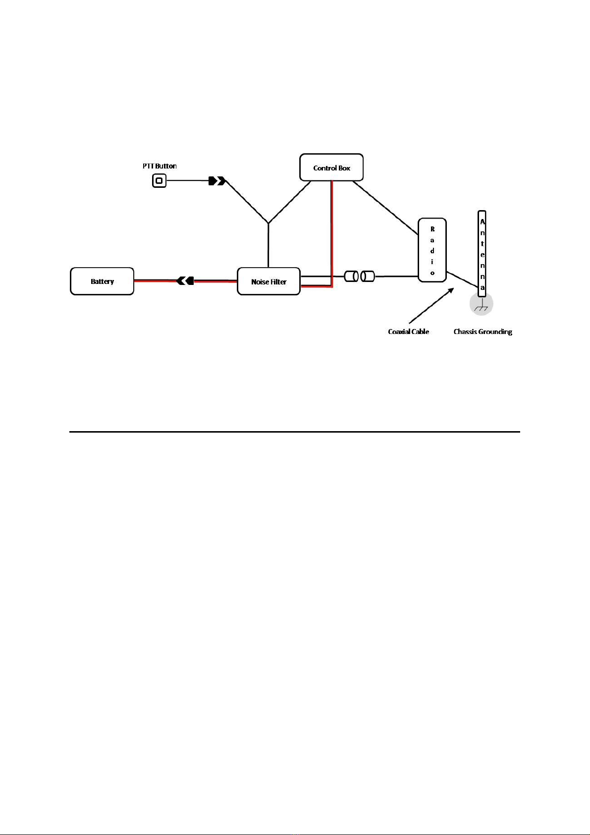
OPTION THREE – EXTERNAL ANTENNA SETUP
Using
the
external
antenna
setup
your
Two
Way
Radio
is
connected
to
an
external
antenna
to
extend
Two
Way
radio
range.
To
connect
your
Two
Way
Radio
using
the
external
antenna
setup
it
is
recommended
to
use
the
Noise
Filter
accessory
to
prevent
the
transmission
of
conductive
noise
from
the
motorcycle
through
the
BikerCom
system;
the
ground
shielding
conductor
should
be
disconnected
from
the
motorcycle
body
at
the
antenna
feed
point,
the
disconnection
of
the
grounding
will
not
affect
the
performance
of
the
antenna.
To
connect
your
Two
Way
Radio
using
the
external
antenna
setup
complete
the
following
steps:
1.
Ensure
the
external
antenna
is
connected
to
your
Two
Way
Radio.
2.
Connect
the
Noise
Filter
to
the
motorcycle
battery.
3.
Connect
the
Noise
Filter
to
the
Two
Way
Radio
charging/power
adapter.
4.
Connect
the
Noise
Filter
to
the
Push
To
Talk
button.
Proceed
with
standard
BikerCom
setup.
19
Option
Three
–
External
Antenna
Setup
Continued…
NOTE:
If
the
external
antenna
produces
unwanted
feedback
noise
it
is
recommended
to
disconnect
the
ground
shielding
from
the
motorcycle
body
at
the
antenna
feed
point;
disconnection
will
not
affect
antenna
performance.
For
more
information
about
chassis
grounding
an
electrical
circuit
contact
the
external
antenna
manufacturer
or
email:
service@openroad.com.tw
NOISE FILTER ACCESSORY
As
mentioned
previously
the
Noise
Filter
accessory
should
be
used
when
your
Two
Way
Radio
is
powered
by
the
motorcycle
battery
and/or
your
Two
Way
Radio
is
connected
to
an
external
antenna
to
extend
Two
Way
radio
range.
Using
the
Noise
Filter
Accessory
prevents
the
transmission
of
conductive
noise
from
the
motorcycle
through
the
BikerCom
system.
The
Noise
Filter
accessory
is
sold
separately
and
not
included
in
the
BikerCom
package
contents.
To
purchase
the
Noise
Filter
accessory
first
contact
the
original
place
of
purchase,
alternatively
you
can
contact
an
authorised
distributor
in
your
region
or
the
manufacturer.
When
using
the
Noise
Filter
Accessory
the
Push
To
Talk
button
must
be
connected
to
the
Noise
Filter
even
if
a
two
way
radio
is
not
being
used;
when
the
Noise
Filter
accessory
is
in
use
only
the
Push
To
Talk
button
can
be
used
for
Powering
On
and
Off
the
Control
Box.
To
use
the
Noise
Filter
accessory
complete
the
following
steps:
1.
Connect
the
Noise
Filter
accessory
lead
labeled
Power
to
the
Power
Cable
with
Fuse
which
is
connected
to
the
motorcycle
battery.
2.
Connect
the
Noise
Filter
accessory
lead
labeled
Control
Box
to
the
Control
Box.
3.
Connect
the
Noise
Filter
accessory
lead
labeled
Power
Adapter
to
the
Two
Way
Radio
charging/power
adapter.
4.
Connect
the
Noise
Filter
accessory
lead
labeled
PTT
to
the
Control
Box
socket
labeled
PTT;
this
is
a
dual
lead,
insert
the
2.5mm
pin.
5.
Connect
the
Noise
Filter
accessory
lead
labeled
PTT
to
the
Push
To
Talk
button;
this
is
a
dual
lead,
insert
the
Push
To
Talk
button
2.5mm
pin.
Proceed
with
standard
BikerCom
setup.

20
Noise
Filter
Accessory
Continued…
Push
To
Talk
Button
Connect
the
Push
To
Talk
Button.
Control
Box
PTT
Connect
to
the
Control
Box
PTT
socket.
Two
Way
Radio
Connect
the
Two
Way
Radio
charging/pow
er
adapter.
Power
Cable
Connect
to
the
Power
Cable.
Control
Box
Connect
to
the
Control
Box
Power
Cable.
Image
not
to
scale.
CONNECTING
WIRED
DEVICES
TO
THE
CONTROL
BOX
CONNECTING THE PUSH TO TALK BUTTON
The
Push
To
Talk
Button
activates
transmission
of
the
Rider
and/or
Passenger’s
voice
over
the
Two
Way
Radio.
To
connect
the
PTT
Button
to
the
Control
Box
complete
the
following
steps:
1.
Ensure
that
the
Control
Box
is
in
Power
Off
mode.
2.
Insert
the
PTT
Button
Connection
Cable
2.5mm
pin
into
the
Control
Box
socket
labeled
PTT.
3.
Using
the
PTT
Adhesive
Pad
affix
the
PTT
Button
to
the
left
handlebar
grip
in
a
position
that
is
easily
accessible
with
your
left
thumb.
NOTE:
Continuous
and
repetitious
activation
of
the
PTT
Button
may
cause
malfunction
and
require
the
BikerCom
system
to
be
restarted.
Table of contents
Other Bikecomm Headset manuals


