manuals.online logo
Brands
  1. Home
  2. •
  3. Brands
  4. •
  5. HEIDENHAIN
  6. •
  7. Measuring Instrument
  8. •
  9. HEIDENHAIN VRZ 780 User manual

HEIDENHAIN VRZ 780 User manual

This manual suits for next models

1

Other HEIDENHAIN Measuring Instrument manuals

HEIDENHAIN MSE 1202 User manual

HEIDENHAIN

HEIDENHAIN MSE 1202 User manual

HEIDENHAIN ND 231B User manual

HEIDENHAIN

HEIDENHAIN ND 231B User manual

HEIDENHAIN ND 7000 User manual

HEIDENHAIN

HEIDENHAIN ND 7000 User manual

HEIDENHAIN GAGE-CHEK 2000 Series User manual

HEIDENHAIN

HEIDENHAIN GAGE-CHEK 2000 Series User manual

HEIDENHAIN AK ERA 4x80 User manual

HEIDENHAIN

HEIDENHAIN AK ERA 4x80 User manual

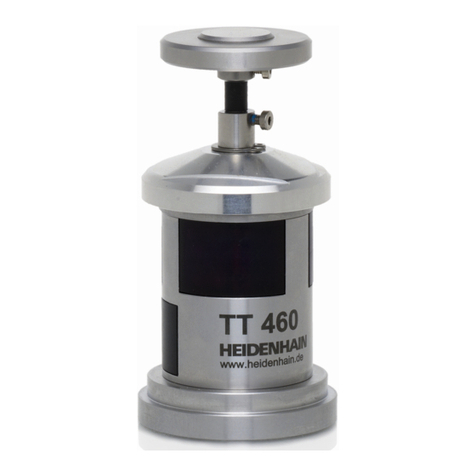
HEIDENHAIN TT 460 User manual

HEIDENHAIN

HEIDENHAIN TT 460 User manual

HEIDENHAIN ND 221 User manual

HEIDENHAIN

HEIDENHAIN ND 221 User manual

HEIDENHAIN LIC 4005 User manual

HEIDENHAIN

HEIDENHAIN LIC 4005 User manual

HEIDENHAIN TS 640 User manual

HEIDENHAIN

HEIDENHAIN TS 640 User manual

HEIDENHAIN QUICK-CHEK QC-1000 User manual

HEIDENHAIN

HEIDENHAIN QUICK-CHEK QC-1000 User manual

HEIDENHAIN ECN 1324 S User manual

HEIDENHAIN

HEIDENHAIN ECN 1324 S User manual

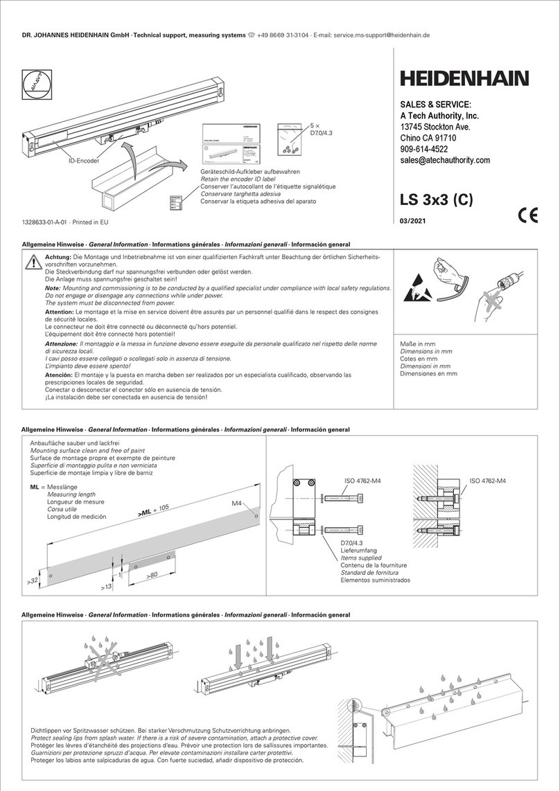
HEIDENHAIN LS 3 3 Series User manual

HEIDENHAIN

HEIDENHAIN LS 3 3 Series User manual

HEIDENHAIN ND 221 User manual

HEIDENHAIN

HEIDENHAIN ND 221 User manual

HEIDENHAIN LC 182 User manual

HEIDENHAIN

HEIDENHAIN LC 182 User manual

HEIDENHAIN ND 200 User manual

HEIDENHAIN

HEIDENHAIN ND 200 User manual

HEIDENHAIN ERN 1381.020 User manual

HEIDENHAIN

HEIDENHAIN ERN 1381.020 User manual

HEIDENHAIN QUADRA-CHEK 2000 User manual

HEIDENHAIN

HEIDENHAIN QUADRA-CHEK 2000 User manual

HEIDENHAIN LIF 48R User manual

HEIDENHAIN

HEIDENHAIN LIF 48R User manual

HEIDENHAIN TS 440 User manual

HEIDENHAIN

HEIDENHAIN TS 440 User manual

HEIDENHAIN SE 661 User manual

HEIDENHAIN

HEIDENHAIN SE 661 User manual

HEIDENHAIN SE 661 User manual

HEIDENHAIN

HEIDENHAIN SE 661 User manual

HEIDENHAIN TS 460 User manual

HEIDENHAIN

HEIDENHAIN TS 460 User manual

HEIDENHAIN LS 603 C User manual

HEIDENHAIN

HEIDENHAIN LS 603 C User manual

HEIDENHAIN TS 460 User manual

HEIDENHAIN

HEIDENHAIN TS 460 User manual

Popular Measuring Instrument manuals by other brands

Powerfix Profi 278296 Operation and safety notes

Powerfix Profi

Powerfix Profi 278296 Operation and safety notes

Test Equipment Depot GVT-427B user manual

Test Equipment Depot

Test Equipment Depot GVT-427B user manual

Fieldpiece ACH Operator's manual

Fieldpiece

Fieldpiece ACH Operator's manual

FLYSURFER VIRON3 user manual

FLYSURFER

FLYSURFER VIRON3 user manual

GMW TG uni 1 operating manual

GMW

GMW TG uni 1 operating manual

Downeaster Wind & Weather Medallion Series instruction manual

Downeaster

Downeaster Wind & Weather Medallion Series instruction manual

Hanna Instruments HI96725C instruction manual

Hanna Instruments

Hanna Instruments HI96725C instruction manual

Nokeval KMR260 quick guide

Nokeval

Nokeval KMR260 quick guide

HOKUYO AUTOMATIC UBG-05LN instruction manual

HOKUYO AUTOMATIC

HOKUYO AUTOMATIC UBG-05LN instruction manual

Fluke 96000 Series Operator's manual

Fluke

Fluke 96000 Series Operator's manual

Test Products International SP565 user manual

Test Products International

Test Products International SP565 user manual

General Sleep Zmachine Insight+ DT-200 Service manual

General Sleep

General Sleep Zmachine Insight+ DT-200 Service manual

Sensa Core Lacto Spark user manual

Sensa Core

Sensa Core Lacto Spark user manual

VOLTCRAFT UTS-1980 operating instructions

VOLTCRAFT

VOLTCRAFT UTS-1980 operating instructions

EBCHQ 94915 Operation manual

EBCHQ

EBCHQ 94915 Operation manual

Balluff BIP LD2-T017-01-EP-S4 Series user guide

Balluff

Balluff BIP LD2-T017-01-EP-S4 Series user guide

Pulsar IMP Lite Series instruction manual

Pulsar

Pulsar IMP Lite Series instruction manual

ETCR 6800 user manual

ETCR

ETCR 6800 user manual

manuals.online logo
manuals.online logoBrands
  • About & Mission
  • Contact us
  • Privacy Policy
  • Terms and Conditions

Copyright 2025 Manuals.Online. All Rights Reserved.

Operating Instructions
VRZ 740,780
Bidirectional Counters
r DR.JOHANNES HEIDENHAIN
Precision Mechanics, Optics and Electronics . Precision Graduations
Post Box 1260 . D-8225 Traunreut . Telephone (08669) 31-I
Telex: 056831 . Telegramme: DIADUR Traunreut
I.Setting up and maintenance
1.1
Items of delivery
Bidirectional counter
VRZ 740 for 2 axes or
Bidirectional counter
VRZ 780 for 3 axes
Replacement fuse 0.4 A slow-blow
(in small compartment at rear of counter)
Mains coupling, separate
optional: mains cable 2.7 m long
Operating instructions and certificate of
inspection
1.2
Technical specifications
Mechanical data
Type
Housing design
Dimensions
VRZ 740 (2 axes display)
VRZ 780 (3 axes display)
table model, cast housing
W 270 x H 221 x D 172 mm
Electrical data
Weight
Operating temperature
Storage temperature
Inputs
Scanning frequency
approx. 5.6 kg
0” to +45” c
-30” to +70° c
for Heidenhain transducers with
grating pitch 20 pm
25 kHz max.
Cable length
Digital displays:
position value displays
keyboard display
Metric/Inch converter
Display step
max. 20 m
7-segment LED’s
7% decades with sign
static, active for all displays
1 pm/2 pm or 0.00005” or 0.0001”
selectable
Datum points
Reference mark evaluation 4 floating datum points
The reference mark positions for all datum
points are automatically stored
independent of power supply. After power
failure, all datum points can be reproduced
by simply passing over the reference L
marks once.
Delta key
Tool radius compensation
conversion of entered absolute
dimensions into incremental dimensions
(= “target” positioning)
keys for entry, and addition to value in
keyboard display, orsubtraction from value
in keyboard display (stored independently
of power supply)
Dimmer switch adjustment of display brightness
3
1.3
Dimensions mm
\
/RZ 740
(2axes)
VRZ 780 (3
axes)
270
!5 133f0,l 87?OJ
i
view A
5
2. Mounting possibilities A further mounting possibility is provided this might result in penetration of the
The counter is cased in a cast aluminium by securing the counter rear onto an angle housing and swat-f entering the counter
housing. The feet of the unit are provided iron or pipe. Drill and tap required holes in interior may cause malfunctions!
with M5- tapped holes which enable accordance with dimensions as indicated
securing onto tables or consoles from in drawing of “rear panel” at any location
underneath by means of screws within the shaded areas. If the indicated
(see drawing of dimensions). dimensions are not strictly observed then
‘, _’ ; , I’
;_ ‘.
: _/, , ‘~
::
‘_
)
view A
view A sectional view B-B
6
3. Connect transducers,
mains connection
CAUTION: Do not engage or disengage
any connectors whilst equipment is under
power.
3.1
Protection
The front panels and the operating panel of
the counters are splashwater-proof.
The counters are provided with failure
signal (see page IO).
Counters VRZ 7401780
correspond to protection classification I of
the VDE-regulations VDE 0411 and are
built and tested in accordance with
DIN 57411 part l/VDE 0411 part 1
“Protective measures for electronic
measuring equipment”.
In order to maintain this condition and to
ensure safe operation, the operator must
comply with the instructions and
warnings which are contained in these
operating instructions.
3.2
Connection of transducers
URZ 740/780
All HEIDENHAIN linear transducers with
20 pm grating pitch
can be connected to VRZ 7401780.
If the standard 4-fold pulse evaluation is
modified to 2-fold (see 3.6 page 9) linear
transducers with
10 pm grating pitch
may also be used.
Angle encoders ROD without built-in pulse The transducer is connected via a g-pole
shaping electronics (e.g. ROD 450) can flange socket
also be connected. Please observe that (Heidenhain Ident;No. 20071901).
the scanning signals are then interpolated
electronically 20-fold or IO-fold (after
modification of the pulse evaluation)
within the counter.
Connector
21235601 contact
designation
use
I ,
Lamp UL
IIL 3 b / 8 Y
+I- + - + -
measuring measuring
signal signal reference ground
(O’el.) (90’ el.) mark signal for
el
Id 60 shieldir
input signals
electrical
values
5v+5% for Heidenhain linear transducers and
angle encoders without built-in pulse
approx. 120 mA shaping electronics
* internal shield to pin 9
external shield to connector housing
3.3
Selection of mains voltage
The counters are set to 220 V- when
supplied, and can be converted to
100, 120, 140,200 or 240 V- :
After removing mains fuse holder,
set voltage selector to desired voltage by
usinq a coin; replace mains fuse holder.
Mains voltage selection Exchanging mains fuse
3.4
Mains connection
Wire.mains cable to enclosed mains
coupling (compl. mains cable available as
accessory) and insert mains coupling into
mains socket of counter. Push down
safety clamp
Wiring of Mains Coupling
CAUTION
Mains connection to contacts 2 3
I I
Protective earth to
8
3.5
Counting direction
The transducers are supplied as follows:
The counting direction can be altered for
each axis individually by shifting the
counting direction switch 1, 2 or 3 beneath
the cover at rear of counter.
Transducer label
\
\
Traversing direction of scale unit
for positive increasing values
Traversing direction of scanning
unit for positive increasing values
Counting direction
positive
negative
Pulse evaluation
2-fold
4-fold
Axis XYZ
X Y forVRZ740
Counting direction
positive
negative
-OPEN-
Pulse evaluation
2-fold
4-fold
Axis XYZ
X Y for VRZ 740
3.6
Pulse evaluation
The pulse evaluation may be altered for all
axes simultaneously at switch 4 of the
counting direction selector from the
standard 4-fold evaluation to 2-fold.
This setting permits connection of linear
transducers with IO pm grating pitch to the
counter.
9
II.Working with VRZ 740/780
By deciding upon counter VRZ 7401780,
you have purchased a unit which, due to
the practical design, makes positioning
easier, quicker and more economical.
This counter offers the possibility of
setting several datum points. Furthermore,
it is possible to position with “target”
counting whereby the tool radius can be
simultaneously taken into account.
Re-establishing the correlation between
datum points and reference marks of the
LS system is “automated”.
Traversing over the reference marks once
is sufficient to calibrate the counter in all
axes. (Previous determination of the
position value for the datum point is not
required.)
In addition to these advantages, the
counters are provided with keyboard entry
(keyboard display), selectable display step,
mm/inch converter, dimmer, direction
switch and pulse evaluation selector.
When reading the following explanations,
it is recommended to refer to the
illustration of the operating panel on
page 20. The encircled figures (0, 0,
0.. .) of a 3 axes counter are explained in
this illustration.
1.1 1.2
Absolute mode and incremental mode
In the absolute mode all measurements
refer to the “absolute” datum point, whilst
in incremental mode each immediately
preceding position serves as datum point.
Absolute mode
Example:
The left upper corner is the “absolute
datum point” for the measurements
Instructions for key-in of position
values or dimensions
Entry errors can be cleared by means of the
q @.
Values are entered in “mm” or “inch”,
whereby key-in of trailing zeroes is not
required.
An entered value remains within the
keyboard memory until it is overwritten by
a new value or cleared with the
q
button @ The finest decade of the key-
board display is rounded off to digital step
0.002 mm inoperating mode “metric”2 pm,
and to 0.00005 inch in “imperial” operating
mode 0.00005.
An entry value can be preset into the
position displays @or can be repeated
any number of times as an incremental
dimension -in any axis and with changing
sign (see item 2.2).
Only negative sign “-‘I is displayed. Each
actuation of the sign change key
q
will
change the sign of the value in the
keyboard memory. For entry of negative
values, the following is applicable: first
enter value, then negative sign.
If the entered value in the kevboard disolav
, ,
The machine is to be positioned to
a certain dimension. is too large (> 5079.999 mm or
199.99995 inches), then each numeral in
the keyboard display will illuminate with
Incremental mode
Example: decimal point.
Measurements are carried out-starting 1.3
from the left upper corner - in increments Traversing over reference marks when
first setting up
After initial connection of transducers, all
REF-memories of the counter must be
“activated”.
”
press REF key @:
reference mark indicators @ in the
position displays illuminate.
Traverse over reference marks in all axes;
referencemarkindicatorsareextinguished.
1.4
The machine is to be traversed by
a certain distance. Gilure signal
Failure of a transducer, cable defects etc.
are indicated by flashing of the appropriate
position display @.
Switch off counter, remedy the fault and
re-active counter. Alternatively, the failure
signal can be cancelled by pressing the
REF key (repeat, if reqd.).
IO
1.5
Operating condition each time counter
is switched on
Keyboard display
Position display
REF key
@ “0”
@ Displayed position values indicate
correlation between established datum
point & and reference mark.
0. “OFF”
IREF(
U
8
mm
8
0 @
inch
0,001 mm
0.00005 inch
g
El
0,:02 mm
0.0001 inch
mm/inch button
Display step
@ metric or imperial (depending on last mode
chosen)
Random switch-over from “mm” to “inch”
and vice-versa during measuring
procedure, whereby the displayed values
and all stored values are simultaneously
converted.
With the display step button @ either
0.001 mm or 0.002 mm
or 0.00005 inch or 0.0001 inch
can be selected as display step for the
position display.
Display brightness maximum brightness
dimmer switch @for two brightness
settings
2. Establishing datum point
2,l
Selection of datum point
The counter permits establishing of four
floating datum points for the position
displays. The dimensioning of a workpiece
may be referenced to different datum
points, i.e. in the following example, datum
point & can be referenced to the
workpiece edge as starting point, and the
other datum points can be referenced to
the centering points of the bore holes for
positioning of the incremental dimensions:
Prior to setting a datum oint, one of the
datum point keys @ $to El
is to be pressed -the corresponding
indicator lamp @ illuminates,
Switch-over between datum points is
possible at any time.