4. Screw the needle locknut out for
more trigger movement, in for
less trigger movement.
5. Adjust the fluid needle so the
trigger moves the air valve
assembly (29) 1/16" before the
fluid needle assembly moves.
6.
Place the needle locknut in the
hex-shaped hole of the rear hous-
ing (25). Be sure the locknut is
properly positioned.
7. Tighten the needle cap with
wrench.
8. Replace stainless steel spring
(20) and fluid control knob (19).
GENERAL INSTRUCTIONS
FOR AIR-SUPPLIED PAINT
SPRAYING
To reduce overspray and obtain
maximum efficiency, always spray
with the lowest possible air pres-
sure that produces an acceptable
spray pattern. Excessive atomizing
air pressure can increase overspray,
reduce transfer efficiency, and with
some materials, result in poor finish
quality from dry spray. Atomizing
air pressures should not exceed
10 psi. See the tables on page 6
and Important Regulatory Note on
page 8.
Generally use 30-35 psi air at the gun
inlet. Unusually heavy or difficult to
atomize materials may require up to
50 psi inlet air. Refer to air pressure
recommendations on page 6.
SPRAY TECHNIQUE
To get a good finish you must handle
the gun properly. Hold the gun per-
pendicular to the surface you are
painting. Each paint stroke should be
made parallel to the plane of the sur-
face being painted. Start the stroke
before you trigger the gun and release
the trigger before you end the stroke.
This will give you accurate control of
both gun and material and will prevent
excessive build-up of material at the
stroke ends.
The distance between the gun and
surface should be 6"-10" depending
on the material and the atomizing
pressure. The material deposited
should always be even and wet. Lap
each stroke about half of the preced-
ing stroke to obtain a uniform finish.
IF YOU HAVE TROUBLE
WITH GUN OPERATION
OR RESULTING FINISH
FAULTY SPRAY PATTERN
A faulty spray pattern is often
caused by dried materials around
the fluid nozzle tip or in the air
nozzle left behind by improper
cleaning. Soak these parts in thin-
ner to soften the material and
remove it with a brush or cloth.
INTERMITTENT SPRAY
Fluttering spray is caused by one of
the following problems:
1. Air leaking into the fluid pas-
sages due to any of the follow-
ing: The packing nut (36) may
be loose. The packing (37) may
be worn and need replacement.
The fluid nozzle (42) may be
loose. The cup assembly (5)
may be loose in the gun. The
fluid inlet seal (39) may be
worn.
2. Insufficient fluid available.
SPITTING
Spitting is caused by anything that
restricts the movement of the fluid
needle assembly (21). The probable
causes include:
1. The packing nut (36) is too tight.
2. The needle assembly (21) is bent.
You may be able to straighten it.
3. Dried material has built up on the
needle or in the fluid nozzle (42).
4. Lumps or impurities in the fluid.
Regulator pressures are based on 25
feet of 1/4" hose in good condition
without quick disconnects or other
restrictive fittings. Gun inlet pres-
sures are measured at the gun air
inlet with the gun triggered. Use the
air nozzle test gauge accessory
54-4150 to confirm the atomizing/
regulator pressure relationship for
your actual air supply setup. These
recommendations are for typical or
average fluids, and are intended to
serve as a starting point. Adjust as
necessary for your specific applica-
tion. Regulator pressures for 5/16"
hose are 3 to 5 PSI lower.
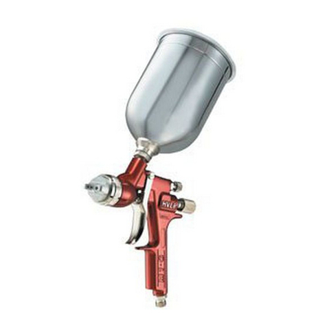
CLEANING and MAINTAINING YOUR Binks CUB SLG GRAVITY-FEED HVLP SPRAY GUN
5
CAUTION
Never use anything metal to clean
the air nozzle or fluid nozzle. These
parts are precisely machined, and
any damage to them will cause
faulty spray patterns.
!
CAUTION
Do not over-tighten as this may
damage the threads and make
future adjustments difficult
.
!
6"-10"
Start
Stroke
Trigger
Gun
End
Stroke
Release
Trigger
SPRAY TECHNIQUE
WARNING
Always wear appropriate gloves,
eye protection and a respirator
when using your gun. Atomized
materials may cause bodily injury.
!
