Bio-Optica BEC150 User manual

Instructions for use
BEC150
Paraffin embedding station
In vitro diagnostic - medical device
CND code: W0202059002
Bio-Optica code: 40-200-002
Reference number code: 1831667
Always keep this manual near the instrument.
Read thoroughly before operating this instrument.

User Manual
Bio-Optica Milano S.p.A. Via San Faustino 58 - 20134 Milan
Phone +39 02.21.27.13.1 - Fax Italy +39 02.21.53.000 - Fax Export +39 02.21.54.155
3
Publication date: 02/03/2020
Rev. 00
IMPORTANT NOTE
The information, figures, notes and estimates in this
documentation represent the most advanced stage of
science and technology and are the result of in-depth
research.
We are not obliged to update this manual regularly in
response to new technical developments, or send revised
versions, updates, etc. for this manual to our clientele.
We accept no liability for any errors in data, notes,
technical illustrations etc. in this manual, in line with
current Italian legislation. In particular, we are not liable in
any way for any damage to property or other indirect
damage arising from failure to comply with instructions or
specific information provided in this manual.
Instructions, drawings, illustrations and any other
technical or general information in this user manual are
not binding with regard to our products.
The provisions of the contract agreed between our
company and the customer prevail in all cases.
Bio-Optica reserves the right to make changes to
technical specifications or the production process without
notice. This is necessary to allow constant progress in
production and technology.
This document is protected by copyright. All copyright is
held by Bio-Optica S.p.A.
Even partial reproduction of the text or illustrations by
printing, photocopying, microfilm, Web Cam or other
methods - including all electronic instruments and
systems - is only permitted with the prior written
authorization of Bio-Optica S.p.A.
The serial number and year of manufacture are provided
on the nameplate affixed to the rear of the device.
Published by:
Bio-Optica S.p.A.
Via San Faustino, 58
20134 Milan
Italy
Telephone (+39) 02-2127131
Fax: (+39) 02-2153000
Internet: info@bio-optica.it

User Manual
Bio-Optica Milano S.p.A. Via San Faustino 58 - 20134 Milan
Phone +39 02.21.27.13.1 - Fax Italy +39 02.21.53.000 - Fax Export +39 02.21.54.155
4
Publication date: 02/03/2020
Rev. 00
TABLE OF CONTENTS
TABLE OF CONTENTS.............................................................................................................................................................4
1 IMPORTANT INFORMATION.......................................................................................................................................5
1.1 PRECAUTIONS FOR USE ...............................................................................................................................5
1.2 SYMBOLS AND THEIR MEANING...................................................................................................................6
1.3 PROPER USE...................................................................................................................................................7
1.4 USER GROUP .................................................................................................................................................. 7
1.5 TYPE OF INSTRUMENT .................................................................................................................................. 7
1.6 SAFETY WARNINGS........................................................................................................................................8
1.7 DANGER WARNINGS ......................................................................................................................................8
2 DESCRIPTION ..................................................................................................................................................................9
2.1 MAIN COMPONENTS.......................................................................................................................................9
2.2 MAIN CHARACTERISTICS ............................................................................................................................10
3 INSTALLATION ..............................................................................................................................................................12
4 USE ..................................................................................................................................................................................13
4.1 INSTRUMENT PARTS....................................................................................................................................13
5 OPERATION ...................................................................................................................................................................16
5.1 CONTROL PANEL..........................................................................................................................................16
5.2 SETTINGS MENU...........................................................................................................................................18
5.3 TIME AND DATE.............................................................................................................................................19
5.4 WEEKLY PROGRAMMING OF WORK SESSIONS.......................................................................................19
5.5 MANUAL MODE..............................................................................................................................................20
5.6 TEMPERATURE SETTINGS..........................................................................................................................22
5.7 USEFUL INFORMATION................................................................................................................................22
5.8 OPERATOR PANEL........................................................................................................................................23
6 CLEANING AND MAINTENANCE...............................................................................................................................25
7 DECLARATION OF CONFORMITY..............................................................................................................................26

User Manual
Bio-Optica Milano S.p.A. Via San Faustino 58 - 20134 Milan
Phone +39 02.21.27.13.1 - Fax Italy +39 02.21.53.000 - Fax Export +39 02.21.54.155
5
Publication date: 02/03/2020
Rev. 00
1IMPORTANT INFORMATION
1.1 PRECAUTIONS FOR USE
Before using the instrument, carefully read the instructions and warnings contained in this manual and keep
them for further reference. They provide important information regarding the functions and safety in installing,
using and maintaining the instrument.
Bio-Optica Milano S.p.A. cannot be held liable for any damage resulting from improper or incorrect use and for
failure to comply with the provisions of this manual and the current safety standards.
1. After removing the packaging, make sure that the instrument is intact without visible damage that may have been
caused by transportation.
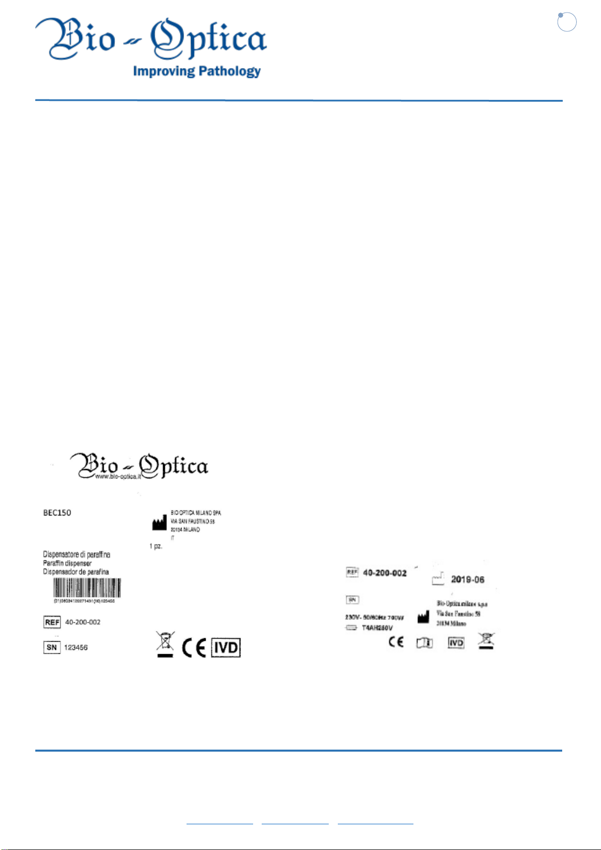
2. Before connecting the instrument, make sure that the data on the nameplate corresponds to that of the power supply.
3. This instrument must only be used for the purpose for which it was expressly designed, that is, as a paraffin dispenser
for laboratory use. Any other use is to be considered improper and therefore hazardous.
4. The instrument must only be used by authorized and professionally qualified personnel.
5. Periodic annual maintenance must be carried out only by qualified personnel authorized by Bio-Optica. For
information, please contact the Technical Assistance Service at Tel. 02-21271310.
6. The electrical safety of this instrument is ensured only when it is correctly connected to an efficient grounding system
as required by current electrical safety standards. It is necessary to check this fundamental safety prerequisite, and if in
doubt, please request a thorough check of the system. The instrument is equipped with a power supply cable having 2
wires + earth to be connected to the power outlet.
7. Do not remove the frame or its parts during operation. Turn off the instrument and disconnect it from the power outlet
before opening it. This operation must only be carried out by authorized and professionally qualified personnel.
8. To eliminate the risk of instrument malfunction, the instrument must operate in an environment free of strong
electromagnetic fields; this means that transmitters such as cell phones should not be used near the instrument.
In case of serious malfunction, turn off the instrument and contact the Technical Assistance Service.
9. All scraps and wastes, both infectious and radioactive, deriving from the work cycle of the instrument must be disposed
of in compliance with the relevant laws in force.
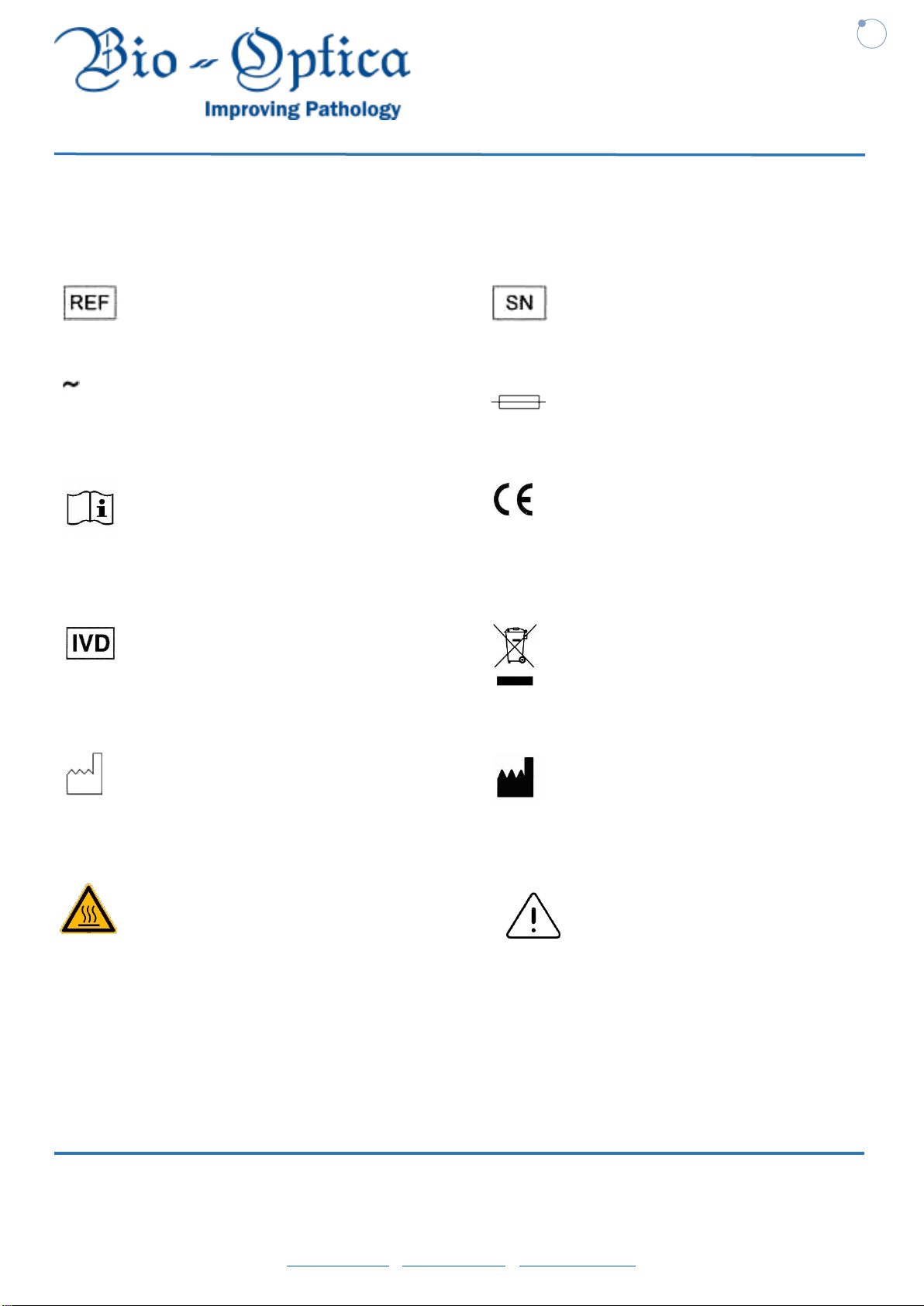
This equipment is marked with the symbol shown on the side, in accordance with the European Parliament
Directive 2002/96/EC and subsequent amendments regarding WEEE (Waste Electrical and Electronic Equipment). This
means that it is forbidden to dispose of this appliance as normal waste; it must instead be taken to a special WEEE
collection center authorized and set up by the Public Administration.
10. The contents of this manual are subject to change without notice.
11. Please find enclosed the declaration of conformity.

User Manual
Bio-Optica Milano S.p.A. Via San Faustino 58 - 20134 Milan
Phone +39 02.21.27.13.1 - Fax Italy +39 02.21.53.000 - Fax Export +39 02.21.54.155
6
Publication date: 02/03/2020
Rev. 00
1.2 SYMBOLS AND THEIR MEANING
Symbol for CATALOG NUMBER:
Symbol for SERIAL NUMBER:
Symbol for ALTERNATING CURRENT:
Symbol for FUSE:
Symbol for CONSULT THE
INSTRUCTIONS FOR USE:
Symbol for CE MARKING:
Symbol for IN VITRO DIAGNOSTIC
MEDICAL DEVICE:
Symbol for DISPOSAL OF ELECTRIC AND
ELECTRONIC EQUIPMENT:
Symbol for DATE OF MANUFACTURE:
Symbol for MANUFACTURER:
WARNING symbol: ATTENTION or WARNING symbol:
hot surface temperatures

User Manual
Bio-Optica Milano S.p.A. Via San Faustino 58 - 20134 Milan
Phone +39 02.21.27.13.1 - Fax Italy +39 02.21.53.000 - Fax Export +39 02.21.54.155
7
Publication date: 02/03/2020
Rev. 00
1.3 PROPER USE
The BEC150 is a modern embedding station for a practical, quick and accurate embedding of paraffin samples.
Thanks to the integration of the thermal unit, the BEC150 can find a place in any pathological anatomy laboratory. The
main functions of the unit are:
• Dissolve solid paraffin for embedding the samples and keep it melted at the required temperature.
• Fill the molds, containing the tissue samples, with paraffin.
• Heat and maintain the temperatures of the embedding cassettes with samples and molds.
• Set and manage temperatures separately for each unit.
This sturdy and ergonomic modular system guarantees a linear and customizable workflow and offers comfort and
ease of use to all users.
1.4 USER GROUP
The BEC150 may only be used by specialized and qualified personnel. Before carrying out any intervention, the user
must read the operating instructions and learn more on all the technical details of the instrument.
1.5 TYPE OF INSTRUMENT
All the information provided in this instruction manual concerns the BEC150 embedding unit. The serial number is
provided on the nameplate affixed to the rear of the instrument.

User Manual
Bio-Optica Milano S.p.A. Via San Faustino 58 - 20134 Milan
Phone +39 02.21.27.13.1 - Fax Italy +39 02.21.53.000 - Fax Export +39 02.21.54.155
8
Publication date: 02/03/2020
Rev. 00
1.6 SAFETY WARNINGS
This user manual contains important instructions and information relating to the operational safety and maintenance of
the instrument. The instruction manual is an important part of the product and must be read thoroughly before installation
and use of the instrument and must always be close to it.
To ensure safe operation, the operator must observe the instructions and warnings contained in this manual. The
protective devices on the instrument and its accessories must not be removed or modified. The tool may only be opened
and repaired by Bio-Optica authorized service technicians.
Use only the power cable supplied and do not replace it with other cables.
If the mains plug does not fit into your outlet, please contact our customer service.
The instrument was built according to the state of the art and recognized technical safety rules.
Improper use or handling may lead to risks of even fatal injury for the user or third parties, or damage to the device or
other property. The instrument is intended only for proper use and in a state of perfect technical safety. Faults that can
compromise safety must be eliminated immediately.
1.7 DANGER WARNINGS
The safety devices, supplied on this instrument by the manufacturer, constitute only the basis for accident protection.
To ensure safe operation of the instrument at all times, certain instructions and warnings must be observed.
During normal operation, some surfaces of the instrument reach high temperatures.
Contact with these surfaces can cause burns. Do not use sharp tools to remove solidified paraffin from workspaces, as
this may destroy the surface coating.
Use the Bio-Optica spatula supplied together with the instrument (40-200-070). During operation, the paraffin tank, the
container for the molds, the tray for the cassettes, the workspace and the forceps-holder are at high temperatures. Risk
of burns!
Do not store any combustible or flammable substance near the instrument. If working with an open flame in the direct
vicinity of the instrument (solvent fumes) there is a risk of fire. Therefore, keep a minimum safety distance of 2 meters.
Switch off the instrument before any maintenance work and remove the mains plug. When using cleaning products,
follow the manufacturer’s safety instructions and laboratory safety rules. Before replacing defective fuses, the instrument
must be disconnected from the mains. Only fuses that are easily accessible may be replaced by the user. When working
or cleaning, make sure that no liquids enter the instrument.

User Manual
Bio-Optica Milano S.p.A. Via San Faustino 58 - 20134 Milan
Phone +39 02.21.27.13.1 - Fax Italy +39 02.21.53.000 - Fax Export +39 02.21.54.155
9
Publication date: 02/03/2020
Rev. 00
2DESCRIPTION
2.1 MAIN COMPONENTS
1. Tank
2. Display
3. On/off button
4. Flow adjustment screw
5. Dispenser with lever and lighting
6. Workspace
7. Heated forceps container
3
2
1
4
12
11
10
9
8
6
5
7
13
13

User Manual
Bio-Optica Milano S.p.A. Via San Faustino 58 - 20134 Milan
Phone +39 02.21.27.13.1 - Fax Italy +39 02.21.53.000 - Fax Export +39 02.21.54.155
10
Publication date: 02/03/2020
Rev. 00
8. Paraffin collection cassettes
9. Cold area
10. Wrist pads
11. Trays with lid
12. Status LEDs
13. Connector for heated forceps and pestles
2.2 MAIN CHARACTERISTICS
Paraffin dispenser for embedding histological samples quickly and cleanly.
The paraffin tank, the workspace, the side trays and the dispensing nozzle are consistently kept at a proper temperature
so as to ensure the constant maintenance of the desired working temperature.
Dimensional characteristics
Dimensions (WxDxH):
560 x 605 x 405 mm.
Paraffin tank capacity:
4 liters
Workplate dimensions (WxD):
517 x 120 mm.
Weight:
18 kg
Power connections
Power supply:
230V~ 50/60Hz.
Power:
700 Watt.
Fuses:
No. 2 x 4 Amp fuses - 5x20 mm - T4AH250V.
Other connections
Water connections:
Not necessary.
Fume extraction/filtration:
Not necessary.
Construction features
Painted sheet metal frame.
Structure consisting of two independently heated and thermostatted workspaces:
Aluminum paraffin tank with lid, used to dissolve the paraffin flakes.
Aluminum work plate with no. 6 housings for forceps and paraffin collection cassette, both heated.

User Manual
Bio-Optica Milano S.p.A. Via San Faustino 58 - 20134 Milan
Phone +39 02.21.27.13.1 - Fax Italy +39 02.21.53.000 - Fax Export +39 02.21.54.155
11
Publication date: 02/03/2020
Rev. 00
Paraffin dispensing system via dispensing nozzle controlled by proximity sensor (maintenance-free) or pedal
(optional accessory). Knob for flow regulation.
Workspace lighting via white LEDs controlled via display.
Cold spot for rapid cooling: 80 x 65 mm spot cooled to approx. -3°C via “Peltier” plate, with independent switch-
on. With wider area suitable for super cassettes as well.
4.3” capacitive touchscreen LCD display.
Detection of paraffin level via integrated level sensors.
Detection of presence of paraffin collection cassettes by means of presence sensors, so as to increase workplace
safety.
Heated and removable forceps-holder for 6 forceps.
Easily adjustable temperatures between 55°C and 75°C for the 3 various zones: workspace, trays and tank.
Option to program switch-on and switch-off times via the interface.
Enhanced heating mode to dissolve paraffin quickly.
Adjustable paraffin flow.
Removable collection trays and cassettes.
Status indicator lights to keep the level of paraffin melting under control even from a distance.
Technical features
Working temperature adjustment:
From +55°C to +75°C via touch screen display
Editing and display of working parameters:
Via touch screen control panel.
Programmability:
Turning the instrument on and off, weekly.

User Manual
Bio-Optica Milano S.p.A. Via San Faustino 58 - 20134 Milan
Phone +39 02.21.27.13.1 - Fax Italy +39 02.21.53.000 - Fax Export +39 02.21.54.155
12
Publication date: 02/03/2020
Rev. 00
3INSTALLATION
Unpack the instrument from the box, taking care not to damage it as you unpack it.
1. Remove the strap and the adhesive tape
2. Remove the cardboard cover
3. Lift and remove the accessories and the internal cover
4. Remove the outer cardboard wall
5. To be able to lift the instrument, grip it only at the lower base of the housing, at the front or rear and pull it out
Installation
Place the instrument on a flat and stable work bench and connect it to the power outlet (230V ~ 50/60Hz) using the
cable supplied.
The stable, vibration-free laboratory table with horizontal top, vibration-free floor as far as possible.
The instrument must not be placed near the air outlet of an air conditioning appliance and must be protected from strong
light (window).
To ensure the full functionality of a heat sink, there must be a distance of at least 15 cm behind the instrument.
There must be no oils or chemical fumes near the work area.
Do not use extension cables or adapters and do not modify the cable supplied.

User Manual
Bio-Optica Milano S.p.A. Via San Faustino 58 - 20134 Milan
Phone +39 02.21.27.13.1 - Fax Italy +39 02.21.53.000 - Fax Export +39 02.21.54.155
13
Publication date: 02/03/2020
Rev. 00
4USE
4.1 INSTRUMENT PARTS
Paraffin tank (1)
The paraffin tank has a capacity of 4 liters. The paraffin temperature can be adjusted between 55°C and 75°C. The lid
must always be in place, otherwise the selected temperature cannot be maintained. A built-in (removable) filter (9)
1
11
5
4
6
3
8
13
7
7
9
10
13
2
13
11
12
12

User Manual
Bio-Optica Milano S.p.A. Via San Faustino 58 - 20134 Milan
Phone +39 02.21.27.13.1 - Fax Italy +39 02.21.53.000 - Fax Export +39 02.21.54.155
14
Publication date: 02/03/2020
Rev. 00
prevents any residue contained in the paraffin from entering the dispensing duct. Inside the tank there are two level
sensors (7), one for low level and one for high level for the paraffin. When the sensors are not covered by paraffin, a
warning is issued to remind you to refill the tank with this visual message:
Recycled paraffins cannot be used in the BEC150 due to the risk of contamination.
Dispenser (2)
The dispenser is heated separately. To get the paraffin to be dispensed, bring a finger or a metal object close to the
gray proximity sensor (10) located under the nozzle or press the pedal (optional accessory). Adjust the flow of paraffin
with the blue knob (8) located above the nozzle.
Workspace (3)
The temperature of the work area can be adjusted between 55°C and 75°C; it
includes the embedding area, the forceps-holder (5) and the cold spot (4). A
groove around the work area and various drainage holes are provided to allow
for quick drainage of liquid paraffin. To clean the workspace, we recommend
using the Bio Optica scraper to remove dried or excess paraffin.
Cold spot (4)
The cold spot is an integral part of the work area.
Its position, directly in front of the embedding area, enables working
comfortably and ergonomically in more favorable conditions. To orient the samples, the mold is filled to about a third
with liquid paraffin. Liquid paraffin begins to solidify rapidly on the cold spot.
While the paraffin is semi-liquid, the sample can be more easily oriented by the technician. Finally, the mold can be
quickly filled with paraffin.
Forceps container (5)
The forceps container can be extracted from under the dispenser and can hold up to 6 forceps.
The forceps-holder is heated separately to approximately 70°C. Risk of burns.

User Manual
Bio-Optica Milano S.p.A. Via San Faustino 58 - 20134 Milan
Phone +39 02.21.27.13.1 - Fax Italy +39 02.21.53.000 - Fax Export +39 02.21.54.155
15
Publication date: 02/03/2020
Rev. 00
Paraffin collection tray (6)
Under the work surface there are two indirectly heated paraffin collection trays, for excess paraffin.
The paraffin collection tray must be emptied daily. To avoid contamination, do not reuse paraffin
collected in this tray. If the instrument is operated without the paraffin collection trays, there is a risk
of spilling liquid paraffin onto the workbench with risk of burns.
Jack for power supply to heated forceps and pestles (11)
Under the jack logo, there are two inputs to connect the heated Bio-Optica forceps directly to the machine. With the two
inputs it is possible to facilitate work for ambidextrous operators or to work with forceps and pestle at the same time.
Trays for molds or cassettes (12)
Depending on the preferred working direction, the two heated trays can be used for molds or cassettes. The temperature
is adjustable between 55 and 75°C. A removable container can be placed in each of the trays. Each container can
contain about 100 cassettes or about 50 molds. A lid is provided for each of the trays to avoid heat loss and contamination
within the tray. For easy access, the lid can be opened, folded back or removed completely.
Lighting (13)
An important feature of the BEC150 is lighting; there are three lighting areas.
The central area of the dispensing nozzle and the two side areas above the thermal tanks.
The LED, in the main part of the instrument, offers diffuse, even lighting of the embedding area and the cold spot. This
allows an optimal view of the tissue embedding and orientation process. The side LEDs can turn yellow when the
machine is heating up and green when the machine is ready for use.

User Manual
Bio-Optica Milano S.p.A. Via San Faustino 58 - 20134 Milan
Phone +39 02.21.27.13.1 - Fax Italy +39 02.21.53.000 - Fax Export +39 02.21.54.155
16
Publication date: 02/03/2020
Rev. 00
5OPERATION
5.1 CONTROL PANEL
The machine is switched on by operating the green main switch; the first time the control panel is switched on it will be
in stand-by mode.
The control panel provides an overview of the machine’s operating status.
The upper part shows a machine status bar, where the date and time, the programmed activities and any operation
warnings appear.
At the corners of the screen are the following machine controls:
1 –MANUAL: to work manually and immediately activate heating.
2 –PELTIER ON/OFF:Peltier cell on/off: enables manually controlling the switching on and off of the desired
temperature.
3 –LED: work light intensity adjustment
4 –SETTINGS MENU:Enables access to functions (see Settings menu)
2
3
4
1

User Manual
Bio-Optica Milano S.p.A. Via San Faustino 58 - 20134 Milan
Phone +39 02.21.27.13.1 - Fax Italy +39 02.21.53.000 - Fax Export +39 02.21.54.155
17
Publication date: 02/03/2020
Rev. 00
In the center of the screen, the image summarizes the operating status of the machine, showing:
- Temperature of the paraffin tank, with relative level.
- Temperature of the side thermal units
- Temperature of the work plate
- Status of the Peltier cell (On/off)
WARNING: The temperatures are visible only when the machine is heating up.
The machine can operate both in MANUAL mode (par. 5.5) and in AUTOMATIC mode (par. 5.4).
The BEC150 offers the option of using an integrated circuit to power the electrically-heated forceps and pestles.
Once the FORCEPS mode is activated, the image of the machine will show two forceps-status check LEDs (as shown
in the image). The LED turns green after the forceps are inserted.

User Manual
Bio-Optica Milano S.p.A. Via San Faustino 58 - 20134 Milan
Phone +39 02.21.27.13.1 - Fax Italy +39 02.21.53.000 - Fax Export +39 02.21.54.155
18
Publication date: 02/03/2020
Rev. 00
5.2 SETTINGS MENU
The settings menu allows adjusting the machine’s operating conditions, as well as allowing a log of operating warnings
(Technical assistance).
Various keys allow access to the menus:
1 –Setting the machine date and time
2 –Weekly work schedule
3 –Adjustment of operating temperatures
1
2
3
4
5
6
7

User Manual
Bio-Optica Milano S.p.A. Via San Faustino 58 - 20134 Milan
Phone +39 02.21.27.13.1 - Fax Italy +39 02.21.53.000 - Fax Export +39 02.21.54.155
19
Publication date: 02/03/2020
Rev. 00
4 –Useful information
5 –Return to the previous screen
6 –Area for technical assistance (not accessible)
7 –Operator panel
5.3 TIME AND DATE
This screen allows setting the machine’s time and weekday.
Note: To correctly set the weekly switch-on and off programming (see corresponding chapter), first set the correct time
and date.
1 –Weekday selection: select the current weekday.
2 –Set the current time
3 –Save settings
5.4 WEEKLY PROGRAMMING OF WORK SESSIONS
This section enables setting the weekly programming of the automatic machine heating on and off.
To use this function, first leave the machine in stand-by mode.
When the working session start time is reached, the machine will start the heating phase of the hot parts; at the end of
the programmed work session the machine will remain on, but will switch to stand-by mode.
3
1
2
4

User Manual
Bio-Optica Milano S.p.A. Via San Faustino 58 - 20134 Milan
Phone +39 02.21.27.13.1 - Fax Italy +39 02.21.53.000 - Fax Export +39 02.21.54.155
20
Publication date: 02/03/2020
Rev. 00
1 –At the top of the screen it is possible to check the programming status for each single day of the week:
- Yellow background: a working session with deadline has been programmed (start and end of work).
- Green background: a continuing work session has been programmed (24H).
- No background: no work session has been set. The machine will remain in stand-by
2 –Details of the work sessions set: it is possible to display the times of the various work sessions. By clicking on the
day box, it is possible to edit the start/end timer
3 –Connection to the time setup screen (see relevant paragraph)
4 –Return to the previous menu
5.5 MANUAL MODE
If the operator does not wish to program the weekly workload, the machine can be operated in manual mode. When
launching this operating mode, the machine will begin the heating phase until the preset temperatures are reached.
The display will now show the temperatures of the various parts; these will be adjustable from the appropriate control
panel (par. 5.6).
1
2
3
4
Table of contents
Other Bio-Optica Laboratory Equipment manuals

Bio-Optica
Bio-Optica Trimming Tech 90 Troubleshooting guide

Bio-Optica
Bio-Optica DP500 User manual

Bio-Optica
Bio-Optica AUS124 Troubleshooting guide

Bio-Optica
Bio-Optica BCP230 User manual

Bio-Optica
Bio-Optica PF200 Troubleshooting guide

Bio-Optica
Bio-Optica TV410 Troubleshooting guide

Bio-Optica
Bio-Optica BCP170 User manual

Bio-Optica
Bio-Optica Piastra Fredda PF100 Troubleshooting guide

Bio-Optica
Bio-Optica UT200 Troubleshooting guide

Bio-Optica
Bio-Optica WB1770 Troubleshooting guide