Bio-Optica AUS124 Troubleshooting guide

User and service manual Stainer AUS124 from sn 101711486
Bio Optica Milano S.p.A. via San Faustino 58 I-20134 Milano
Tel. +39 02.21.27.13.1 Fax Acquisti/Export +39 02.21.54.155
Fax Assistenza/Contabilità +39 02.26.41.74.48 Fax Vendite +39 02.21.53.000
Revision 170517 of 17/05/17
Page 1 of 41
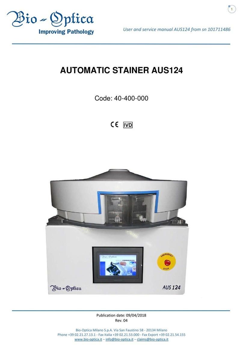
AUTOMATIC STAINER AUS124
Code: 40-400-000

User and service manual Stainer AUS124 from sn 101711486
Bio Optica Milano S.p.A. via San Faustino 58 I-20134 Milano
Tel. +39 02.21.27.13.1 Fax Acquisti/Export +39 02.21.54.155
Fax Assistenza/Contabilità +39 02.26.41.74.48 Fax Vendite +39 02.21.53.000
Revision 170517 of 17/05/17
Page 2 of 41
USE PRECAUTIONS
Before using the instrument, read carefully the instructions and warnings contained in this
manual and keep it for further reference. They supply important indications regarding the
functions and safety for installing, using and maintaining the instrument.
Bio-Optica Milano S.p.A. cannot be held responsible for any damage caused by improper or
incorrect use and by the non-observance of any of the prescription provided in this manual
and by the safety regulations in force.
1. After unpacking, make sure that the instrument is complete and not damaged by transport.
2. Before connecting the instrument to the power supply make sure that its rating corresponds to that of the power
supply.
3. This instrument must only be used for the purpose for which it was designed, that is, as automatic stainer for
laboratory use. Any other use is to be considered improper and therefore hazardous.
4. The instrument must only be used by authorized and professionally qualified technician.
5. The electrical safety of this instrument can be guaranteed only if it is correctly connected to an efficient earth circuit
as indicated by current electrical safety regulations. It is necessary to check this fundamental safety prerequisite, and if
in doubt, ask to check the circuit. The instrument is provided with a power supply cable having 2 wires + ground tap that
have to be connected to the power supply socket.
6. Do not remove the chassis or parts of it during operation. Switch off the instrument and disconnect the power supply
cable before opening it. This operation must to be effected only by authorized and professionally qualified technician.
7. To eliminate instrument malfunctioning risks, do not work near strong magnetic fields and do not use transmitters
such as cellular phones near the instrument. In case of serious malfunctioning switch off the instrument and contact the
Technical Assistance Service.
8. All waste material, both infectious and radioactive, deriving from the appliance working cycle must be disposed in
compliance with the regulation in force.
This appliance is marked from this symbol, in compliance with EU directive 2002/96/CE regarding
electric and electronic appliances waste. This mean that the instrument, at the end of its useful life, must be collected
separately from other refuse. The user must deliver it to the special differentiated refuse collection centres, that are
predisposed by the public authority.
9. The contents of this manual is subject to change without further notice.
10. Please find enclosed the declaration of conformity.

User and service manual Stainer AUS124 from sn 101711486
Bio Optica Milano S.p.A. via San Faustino 58 I-20134 Milano
Tel. +39 02.21.27.13.1 Fax Acquisti/Export +39 02.21.54.155
Fax Assistenza/Contabilità +39 02.26.41.74.48 Fax Vendite +39 02.21.53.000
Revision 170517 of 17/05/17
Page 3 of 41
11. Graphic symbols indicated on the label (positioned near the instrument’s power supply socket):
Symbol for CATALOGUE NUMBER:
Symbol for SERIAL NUMBER:
Symbol for ALTERNATING CURRENT:
Symbol for FUSE:
Symbol for CONSULT THE INSTRUCTIONS:
Symbol for EC MARKING:
Symbol for IN VITRO DIAGNOSTIC-MEDICAL DEVICE:
Symbol for DISPOSAL OF ELECTRIC AND ELECTRONIC EQUIPMENT:
Symbol for DATE OF MANUFACTURE:
Symbol for MANUFACTURER:

User and service manual Stainer AUS124 from sn 101711486
Bio Optica Milano S.p.A. via San Faustino 58 I-20134 Milano
Tel. +39 02.21.27.13.1 Fax Acquisti/Export +39 02.21.54.155
Fax Assistenza/Contabilità +39 02.26.41.74.48 Fax Vendite +39 02.21.53.000
Revision 170517 of 17/05/17
Page 4 of 41
INDEX
1) Technical features. Page 5
2) Installation. Page 7
3) Water connections. Page 7
4) Control panel. Page 11
5) Date and hour setup. Page 12
6) Instrument’s start. Page 13
7) Instructions for the rotation of the dish holder disk. Page 17
8) Parameters setup and programming. Page 19
9) Alarms. Page 31
10) Maintenance and filters replacement. Page 33
11) Programmed maintenance and Instrument cleaning. Page 34
12) Main safety elements. Page 34
13) Main components. Page 34
14) Problem solving. Page 36
15) Fuses replacement. Page 37
16) Electric wiring diagram. Page 38
17) Declaration of conformity. Page 41

User and service manual Stainer AUS124 from sn 101711486
Bio Optica Milano S.p.A. via San Faustino 58 I-20134 Milano
Tel. +39 02.21.27.13.1 Fax Acquisti/Export +39 02.21.54.155
Fax Assistenza/Contabilità +39 02.26.41.74.48 Fax Vendite +39 02.21.53.000
Revision 170517 of 17/05/17
Page 5 of 41
1) TECHNICAL FEATURES
Carousel automatic stainer for colouring histological and cytological slides.
Dimensional features
Dimensions (WxDxH): 750x750x650 mm.
Weight: 75 Kg.
Electrical connections
Power supply: 230V~ 50/60Hz.
Power: 120 Watt.
Other connections
Water connections: Provided pipes for supplying the running water dishes:
N. 1 running water inlet pipe, internal Ø 10 mm, provided with rapid connection with
interception.
N. 1 running water outlet pipe, internal Ø 18 mm.
N. 2 neoprene pipes - internal Ø 10 mm, one metre long - provided with rapid connection
with interception (for the connection between the dishes and the instrument).
Water pressure: From 2,5 to 4 bar.
Structural features
Painted steel chassis resistant to scratches and solvents.
On the right side are placed: N. 1 green general switch, N. 1 power supply socket with relative fuses, N. 2
connecters for pipes connecting running water dishes/instrument.
On the left side are placed: N. 1 connecter connecting running water inlet pipe, N. 1 connecter connecting
running water outlet pipe, N. 1 running water pressure regulator, N. 1 filter seat cover provided with handle.
External cover for containing fumes.
Basket holder cover, positioned under the external cover, provided with 24 guides for coupling one or more
baskets and 24 stainless steel covers for covering the dishes.
Central basin for carrying waste water from wash dishes to the drain placed on the left side of the instrument.
N. 4 adjustable rubber feet to get a perfect horizontal position.
Aspiration/filtration system for the treatment of fumes. The instrument is provided with N. 1 active charcoal
cartridge filter specific for alcohol and xilol. Practical filter’s replacement from the left side of the instrument.
Revolving dish holder disk to facilitate the access to the dishes placed on the back side.
N. 2 stainless steel slide holder baskets (capacity 65 standard slides 26x76 mm).
N. 21 reagents dishes (capacity 750 ml) in white thermoplastic material.

User and service manual Stainer AUS124 from sn 101711486
Bio Optica Milano S.p.A. via San Faustino 58 I-20134 Milano
Tel. +39 02.21.27.13.1 Fax Acquisti/Export +39 02.21.54.155
Fax Assistenza/Contabilità +39 02.26.41.74.48 Fax Vendite +39 02.21.53.000
Revision 170517 of 17/05/17
Page 6 of 41
N. 1 dish (capacity 750 ml) in white thermoplastic material for baskets load/discharge in position 0.
N. 2 running water dishes (capacity 750 ml) in transparent thermoplastic material.
N. 2 independent electric valves which activate the water flow when there is the passage in running water.
Pressure regulator to regulate the water flow.
Working features
General ignition switch.
Emergency switch for stopping all the machine functions at any time.
Entire management of the instrument through use of single colour touch screen panel with intuitive graphics.
Possibility of visualizing steps of program during the execution of the cycle.
Possibility of memorizing more than 999 different protocols of coloration, with maximum number of 48 steps for
each.
Possibility of programming for each station: time of immersion/oscillation and dripping from 00’ : 01’’ up to 59’ :
59’’.
Page of visualization and description of alarms accessible also during the execution of the program.
Possibility of stopping and restarting a program (in case of possible controls, filling up of reagents, ecc.).
Visual and acoustic alarm in case of cycle end.
Visual and acoustic alarm in case of filter saturation.
Visual and acoustic alarm in case of table out of position.
Visual and acoustic alarm for water discharge (malfunction of electric valve, obstruction discharge pipes, etc.).
Possibility of visualizing the steps of the stations during the cycle.
Possibility of programming without leaving the general program page.
Possibility of varying the parameters of the steps also during the execution of the running program.
Possibility of deleting the program steps without leaving the general page.
Visualization of programs time already executed by date and hour.

User and service manual Stainer AUS124 from sn 101711486
Bio Optica Milano S.p.A. via San Faustino 58 I-20134 Milano
Tel. +39 02.21.27.13.1 Fax Acquisti/Export +39 02.21.54.155
Fax Assistenza/Contabilità +39 02.26.41.74.48 Fax Vendite +39 02.21.53.000
Revision 170517 of 17/05/17
Page 7 of 41
2) INSTALLATION
During the stainer moving, proceed cautiously in order to avoid possible damages.
Position the instrument on a level and stable working bench, free of vibrations. Make sure that on the upper part there is
space enough (ca. 30 cm) to allow the ascent/descent movements of the cover. Regulate the 4 rubber feet to get a
perfect horizontal position. Connect the instrument to the power supply socket (230V~ 50/60Hz) using the provided
cable.
Important:
Do not use any extension or adapter and do not modify the provided cable.
Respect the following working environmental conditions:
Room temperature between 10°C and 40°C.
Relative humidity between 30% and 75%.
Maximum temperature inlet water: 40°C.
3) WATER CONNECTIONS
Inlet running water
Connect the provided pipe ( 10 mm) between the connecter placed on the left side of the instrument and a water tap.
Outlet running water
Connect the provided pipe ( 18 mm) between the connecter placed on the left side of the instrument and the drain of
the laboratory.
Important: As the draining happens by fall, it is necessary that the pipe is positioned as linear as possibile and
downhill (the water outlet connecter of the stainer must be situated over del water outlet connecter of the laboratory).
Connection between the two running water dishes and the instrument
Connect the two provided pipes ( 10 mm) between the connecters of the running water dishes and the connecters
situated on the right side of the instrument. Choose the position of the dishes according to the main programme. Make
sure that the pipes are long enough to rotate the dishes holder disk.

User and service manual Stainer AUS124 from sn 101711486
Bio Optica Milano S.p.A. via San Faustino 58 I-20134 Milano
Tel. +39 02.21.27.13.1 Fax Acquisti/Export +39 02.21.54.155
Fax Assistenza/Contabilità +39 02.26.41.74.48 Fax Vendite +39 02.21.53.000
Revision 170517 of 17/05/17
Page 8 of 41
Left side of the instrument.
Right side of the instrument.
Water inlet connecter
Water outlet connecter
Pressure regulator
Filter seat
Green
general switch
Connecter for wash
dish N. 2
Connecter for wash
dish N. 1
Power supply
socket

User and service manual Stainer AUS124 from sn 101711486
Bio Optica Milano S.p.A. via San Faustino 58 I-20134 Milano
Tel. +39 02.21.27.13.1 Fax Acquisti/Export +39 02.21.54.155
Fax Assistenza/Contabilità +39 02.26.41.74.48 Fax Vendite +39 02.21.53.000
Revision 170517 of 17/05/17
Page 9 of 41
Adjustment of the pressure reducer valve
The pressure reducer valve regulates the water flow when the pressure of the plant is irregular or not adjustable.
Instructions for the flow adjustment:
1) In main menu touch key MANUAL CONTROLS.
2) Enable the wash dishes touching keys OFF by WATER 1 and WATER 2.
3) Open abundantly the water.
4) Pull the knob till you hear a click and rotate it till you get the right quantity of water (clockwise to increase the flow,
anticlockwise to reduce it).
5) Finished the adjustment, block the valve by pressing the knob till you hear a click.
6) Disable the wash dishes touching keys 1 or 2 (enabled water green button, disabled water red button).
7) In order to return to menu, touch exit key positioned low on the left.

User and service manual Stainer AUS124 from sn 101711486
Bio Optica Milano S.p.A. via San Faustino 58 I-20134 Milano
Tel. +39 02.21.27.13.1 Fax Acquisti/Export +39 02.21.54.155
Fax Assistenza/Contabilità +39 02.26.41.74.48 Fax Vendite +39 02.21.53.000
Revision 170517 of 17/05/17
Page 10 of 41

User and service manual Stainer AUS124 from sn 101711486
Bio Optica Milano S.p.A. via San Faustino 58 I-20134 Milano
Tel. +39 02.21.27.13.1 Fax Acquisti/Export +39 02.21.54.155
Fax Assistenza/Contabilità +39 02.26.41.74.48 Fax Vendite +39 02.21.53.000
Revision 170517 of 17/05/17
Page 11 of 41
4) CONTROL PANEL
Touch screen control panel, intuitive, impermeable IP55 for the programming/modification/visualization of the
parameters of work and the control of the process of coloration.

User and service manual Stainer AUS124 from sn 101711486
Bio Optica Milano S.p.A. via San Faustino 58 I-20134 Milano
Tel. +39 02.21.27.13.1 Fax Acquisti/Export +39 02.21.54.155
Fax Assistenza/Contabilità +39 02.26.41.74.48 Fax Vendite +39 02.21.53.000
Revision 170517 of 17/05/17
Page 12 of 41
FUNCTIONS DESCRIPTION
PROGRAMMING
STEPS Selecting this function you access the page of steps programming.
CYCLE START Direct access to the running program page.
SET DATE Function for changing date and hour.
BIO-OPTICA – LOG IN Page under password of exclusive use of technical assistance.
MANUAL CONTROLS Access to the page for the management of manual functions.
WORK HOURS -
GRAPH History visualization of times and dates for programs already executed.
LANGUAGE Selecting this function you can set the language (Italian/English).
5) SETUP DATE AND HOUR
It is possible set up date and hour by selecting the icon in the main menu to the entry SET DATE.
Set up the desired date and hour and confirm all the set up data touching key “CONFIRM”.
Press exit key law on the right in order to return to menu.

User and service manual Stainer AUS124 from sn 101711486
Bio Optica Milano S.p.A. via San Faustino 58 I-20134 Milano
Tel. +39 02.21.27.13.1 Fax Acquisti/Export +39 02.21.54.155
Fax Assistenza/Contabilità +39 02.26.41.74.48 Fax Vendite +39 02.21.53.000
Revision 170517 of 17/05/17
Page 13 of 41
6) INSTRUMENT’S START
Switch on the instrument by pressing the green main switch placed on the right side of the instrument.
On display appears the initial screen and a sound signal advises that the machine is working.
Touch the screen to page to main menu of the functions.
IMPORTANT: When the machine is switched on, it is necessary to reset the axes position. Select START CYCLE and
then press the STOP button. The machine will position with the basket on the first station and with the vertical axis in
the high end position. Only now you can proceed with the use of all the functions.

User and service manual Stainer AUS124 from sn 101711486
Bio Optica Milano S.p.A. via San Faustino 58 I-20134 Milano
Tel. +39 02.21.27.13.1 Fax Acquisti/Export +39 02.21.54.155
Fax Assistenza/Contabilità +39 02.26.41.74.48 Fax Vendite +39 02.21.53.000
Revision 170517 of 17/05/17
Page 14 of 41
6.1 MANUAL OPERATIONS
To access the manual functions press the icon near MANUAL CONTROLS in the main menu.
In manual function it is possible to manage manually the machine movements and check the correct operation of the
electric valves of waters management.

User and service manual Stainer AUS124 from sn 101711486
Bio Optica Milano S.p.A. via San Faustino 58 I-20134 Milano
Tel. +39 02.21.27.13.1 Fax Acquisti/Export +39 02.21.54.155
Fax Assistenza/Contabilità +39 02.26.41.74.48 Fax Vendite +39 02.21.53.000
Revision 170517 of 17/05/17
Page 15 of 41

User and service manual Stainer AUS124 from sn 101711486
Bio Optica Milano S.p.A. via San Faustino 58 I-20134 Milano
Tel. +39 02.21.27.13.1 Fax Acquisti/Export +39 02.21.54.155
Fax Assistenza/Contabilità +39 02.26.41.74.48 Fax Vendite +39 02.21.53.000
Revision 170517 of 17/05/17
Page 16 of 41
1 = Visualizes the status of the engine brakes. The status of the engine brakes is automatically actuated at the entrance
in this page and allows to move the axis.
ATTENTION: If the vertical axis is not in the high security location, you can not activate the rotary axis.
2 = Movement function towards the top of the vertical axis. While pressing the button, the vertical axis will move upward
to its end high.
3 = Movement function towards the bottom of the vertical axis. While pressing the button, the vertical axis will move
downwards to its end.
4 = Enable/disable the operation of the electric valve of management of water basin n ° 2.
5 = Enable/disable the operation of the electric valve of management of water basin n ° 1.
6 = Touching this icon is possible to position the basket on the desired basin. Select the basin number and press enter
on the numeric table.
7 = This button allows the rotational movement. By pressing this button, the basket will be placed in the selected basin.
ATTENTION: If the vertical axis is not in the high security position, you can not activate the rotary axis.
1
3
6
2
4
7
5

User and service manual Stainer AUS124 from sn 101711486
Bio Optica Milano S.p.A. via San Faustino 58 I-20134 Milano
Tel. +39 02.21.27.13.1 Fax Acquisti/Export +39 02.21.54.155
Fax Assistenza/Contabilità +39 02.26.41.74.48 Fax Vendite +39 02.21.53.000
Revision 170517 of 17/05/17
Page 17 of 41
7) INSTRUCTIONS FOR THE ROTATION OF THE DISH HOLDER DISK
The swivel dish holder disk allows to accede easily to the dishes positioned on the back.
In main menu touch key MANUAL COMMANDS.
Take the basket-holder cover to its end in height as shown in the previous chapter.
Pull the release knob and rotate cautiously the disk in the desired position taking care to the pipes connected to
the dishes as shown in the sequence in succession.
1) When the machine is stopped, identify the release knob.

User and service manual Stainer AUS124 from sn 101711486
Bio Optica Milano S.p.A. via San Faustino 58 I-20134 Milano
Tel. +39 02.21.27.13.1 Fax Acquisti/Export +39 02.21.54.155
Fax Assistenza/Contabilità +39 02.26.41.74.48 Fax Vendite +39 02.21.53.000
Revision 170517 of 17/05/17
Page 18 of 41
2) Release the knob to unlock the trays holder disc.
3) Rotate the disc with caution in the desired position.

User and service manual Stainer AUS124 from sn 101711486
Bio Optica Milano S.p.A. via San Faustino 58 I-20134 Milano
Tel. +39 02.21.27.13.1 Fax Acquisti/Export +39 02.21.54.155
Fax Assistenza/Contabilità +39 02.26.41.74.48 Fax Vendite +39 02.21.53.000
Revision 170517 of 17/05/17
Page 19 of 41
8) SETUP PARAMETERS AND PROGRAMMING
8.0 SETUP OF PARAMETERS, STEPS OF COLORATION AND SAVE OF A PROGRAM
It is possible to program the machine both in the page dedicated to the PROGRAMMING STEPS and in the page of
running program. Below sequences for programming:
1. Access the main menu.
2. Select PROGRAMMING STEPS. Appears the window that shows 48 boxes, one for each programmable step.

User and service manual Stainer AUS124 from sn 101711486
Bio Optica Milano S.p.A. via San Faustino 58 I-20134 Milano
Tel. +39 02.21.27.13.1 Fax Acquisti/Export +39 02.21.54.155
Fax Assistenza/Contabilità +39 02.26.41.74.48 Fax Vendite +39 02.21.53.000
Revision 170517 of 17/05/17
Page 20 of 41
3. Starting from first step of program P1 up on the left, set up the desired parameters for each step of program:
n° position = number of the position relative to the desired dish from 1 to 24.
T. immersion/oscillation = time of immersion or oscillation of the basket in a dish measured in minutes and
seconds.
T. dripping = shows the time of dripping of a basket after the phase of immersion outside the dish, measured in
minutes and seconds.
H2O 1 = activates (green colour) or deactivates (red colour) the flow of running water in the dish N. 1 for the
whole duration of immersion of the basket. The water will begin to flow into the dish already from the previous
step in order to obtain clean water on arrival of the basket.
H2O 2 = activates (green colour) or deactivates (red colour) the flow of running water in the dish N. 2 for the
whole duration of immersion of the basket. The water will begin to flow into the dish already from the previous
step in order to obtain clean water on arrival of the basket.
Set up the parameters in each step, touching on the screen the value to set up.
4. IMPORTANT: It is necessary to set in the last step of program the dripping time value "0" so that the
control consider this as the last step of the program.
5. To save the program with the set parameters, touch the button PROGRAM. Appears the screen where you can
manage the programs backup.
• Select the box relative to the program number and type the program number (from 1 to 999).
• Select the box relative to the program name and name it by using the alphanumeric keypad.
• Save the program by touching the yellow button SAVE RECIPE, the control asks you to confirm the save.
Other manuals for AUS124
2
Table of contents
Other Bio-Optica Laboratory Equipment manuals

Bio-Optica
Bio-Optica BEC150 User manual

Bio-Optica
Bio-Optica Trimming Tech 90 Troubleshooting guide

Bio-Optica
Bio-Optica PF200 Troubleshooting guide

Bio-Optica
Bio-Optica AUS124 Troubleshooting guide

Bio-Optica
Bio-Optica DP500 User manual

Bio-Optica
Bio-Optica TV410 Troubleshooting guide

Bio-Optica
Bio-Optica UT200 Troubleshooting guide

Bio-Optica
Bio-Optica WB1770 Troubleshooting guide

Bio-Optica
Bio-Optica AUS124 Troubleshooting guide

Bio-Optica
Bio-Optica Piastra Fredda PF100 Troubleshooting guide