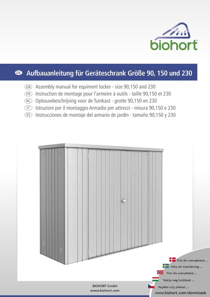
manuals.online logo
Brands
  1. Home
  2. •
  3. Brands
  4. •
  5. Biohort
  6. •
  7. Garden House
  8. •
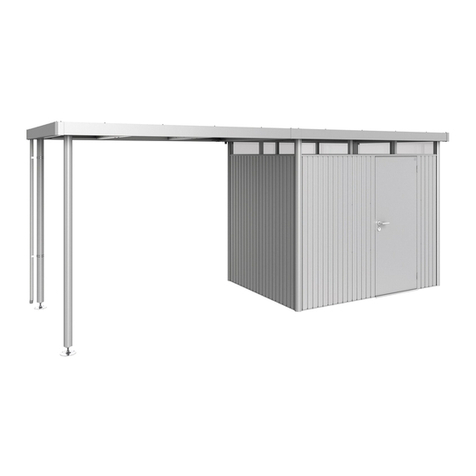
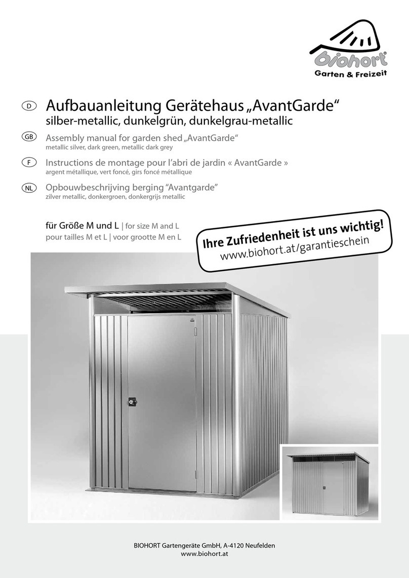
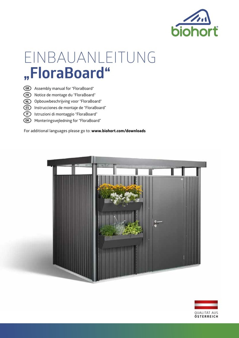
  9. Biohort AvantGarde XL User manual

Biohort AvantGarde XL User manual

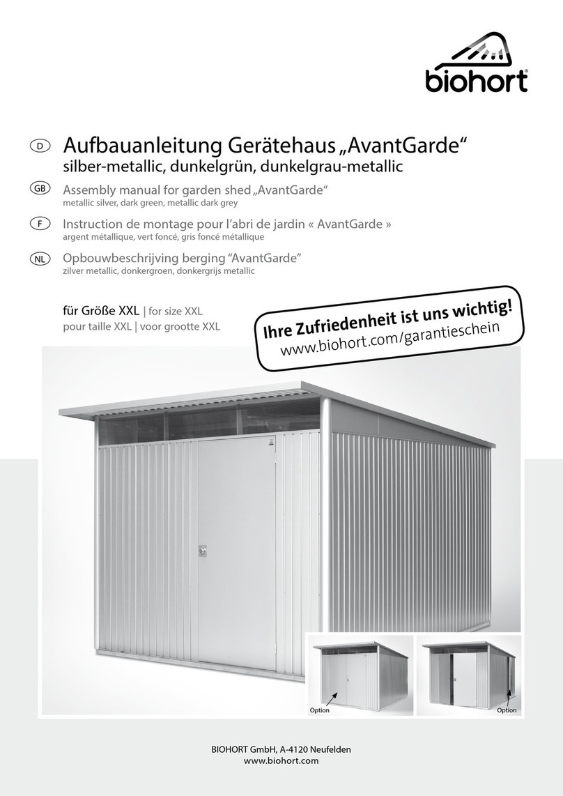
Aufbauanleitung Gerätehaus „AvantGarde“
silber-metallic, dunkelgrün
Assembly manual for garden shed „AvantGarde“
metallic silver, dark green
Instructions de montage pour l’abri de jardin « AvantGarde »
argent métallique, vert foncé
Opbouwbeschrijving berging “Avantgarde”
zilver metallic, donkergroen
GB
F
NL
D
für Größe XL |for size XL
pour taille XL | voor grootte XL
BIOHORT Gartengeräte GmbH, A-4120 Neufelden
www.biohort.at
ONLINE INFORMATION:
www.biohort.at
Option Option
2
GB F NLD
Important Details
regarding assembly
• A parts list and plan view is
also included.
• For several assembly steps
additional assistance of 1 or 2
people will be required.
• The door wings can also be
fitted in one of the side walls.
• Nuts not to be tightened
before the end of assembly!
• Before installing accessories
(i.e. 2nd door wing, floor frame,
floor panels):
first of all please read the
relevant instructions for fitting
(provided within the packaging
of each accessory).
Recommandations
importantes pour le
montage
• L’inventaire des pièces et un
plan y sont joints.
• Pour certaines phases de
montage, prévoyez l’aide
d’une ou deux personnes.
• Vous pouvez également monter
la porte dans une paroi latérale.
• Ne serrer les écrous à fond
qu’à la fin de l’assemblage !
• Montage 2ème porte et autres
accessoires : faites bien atten-
tion s’il vous plait. aux indica-
tions de montage jointes.
Belangrijke tips
voor montage
• De onderdelenlijst en een
plattegrond zijn bijgesloten.
• Voor enige montage stappen
heeft u de hulp van 1 tot 2
personen nodig.
• U kunt de deuren ook in een
zijwand inbouwen.
• De moeren dienen pas aan
het einde van de montage
vastgeschroefd te worden!
• Bij montage van de 2e deur en
verdere toebehoren, let u s.v.p.
op de bijgevoegde montage
tips bij deze toebehoren.
Wichtige Hinweise
zur Montage
• Die Stückliste und ein
Grundrissplan liegen bei.
• Für einige Montageschritte
benötigen Sie 1 bis 2 Helfer.
• Sie können die Flügeltüre auch
in einer Seitenwand einbauen.
• Schraubenmuttern erst
am Ende der Montage
festziehen!
• Montage 2. Türflügel und wei-
teres Zubehör: bitte beachten
Sie die diesem Zubehör beilie-
genden Montagehinweise.
Pflege und Wartung
• Ölen Sie das Schloss und die
Scharniere jährlich!
• Dach von Laub freihalten,
keine Chemikalien lagern!
• Kratzer sofort mit beilie-
gendem Lack ausbessern!
Care and
maintenance
• Lubricate the hinges and the
lock once a year!
• Keep the roof free of leaves,
do not store chemicals!
• Touch-up scratches immedia-
tely with the paint provided!
Entretien et
maintenance
• Graisser la serrure et les
charnières une fois par an !
• Débarrasser le toit des feuil-
lages ; ne pas entreposer de
produits chimiques !
• Retoucher aussitôt les rayures à
l’aide de la laque jointe !
Onderhoud
• Geef het slot en scharnieren
jaarlijks olie!
• Hou het dak vrij van bladeren;
geen chemicaliën opslaan!
• Krassen direct met de
bijgeleverde lak bijwerken!
ATTENTION
• Do not assemble the shed on a
windy day!
• Wear working gloves - some
of the metal pieces may have
sharp edges!
• When making the foundation
arrangements consider the
possibility of heavy rain-fall,
take necessary precautions to
ensure that water cannot leak
in under the floor profiles (i.e. a
raised foundation).
• Do not forget to anchor the
shed against gale force wind!
ATTENTION
• Ne pas assembler l’abri de
jardin lorsqu’il y a du vent !
• Porter des gants, certaines
parties métalliques peuvent
être coupantes !
• Penser aux fortes pluies lors de
la réalisation de la fondation :
l’eau de ruissellement ne doit
pas pouvoir pénétrer sous les
profils de sol, à l’intérieur de
l’abri de jardin (ex : fondation
surélevée).
• Ne pas oublier l’ancrage
contre le vent !
LET OP
• Berging niet bij wind opbouwen!
• Gebruik werkhandschoenen –
sommige metalen onderdelen
kunnen scherpe kanten
hebben!
• Denk bij het plaatsen van de
fundering aan de mogelijk-
heid van sterke regenval; het
oppervlaktewater mag niet
onder het bodemprofiel in de
berging kunnen binnendringen
(bijv. een verhoogd fundament).
• Denkt u aan een stormzekere
verankering!
ACHTUNG
• Gerätehaus nicht bei Wind
aufbauen!
• Arbeitshandschuhe verwenden
– einige Blechteile können
scharfkantig sein!
• Denken Sie bei der Fundament-
gestaltung an starke Regenfälle:
das Oberflächenwasser darf
nicht unter den Bodenprofilen
in das Gerätehaus eindringen
können (z.B. erhabenes
Fundament).
• Sturmfeste Verankerung
nicht vergessen!
3
Bitte achten Sie bei der Fundamentgestaltung darauf, dass Niederschlagswasser nicht seitlich unter den Bodenprofilen in das Gerätehaus
eindringen kann! (siehe Varianten 1, 2, 3). Aufsteigende Bodenfeuchtigkeit und Kondensation vermeiden Sie mittels einer starken Kunststoff-
folie unter den Betonplatten bzw. unter dem Betonfundament. Gegen eindringendes Oberflächenwasser das Bodenprofil zum Fundament mit
Baudichtmasse abdichten (siehe Fundamentvariante 2).
While preparing the foundations please pay attention to ensure that rain water can not enter underneath the sides of the floor profiles!
(See proposals 1, 2 & 3) A plastic sheet placed under the entire floor area will reduce moisture and condensation.
Against intrusion of surface water you should apply a metal compatible sealant to the underside of the floor profile (see proposal 2).
Faites attention lors de la mise en œuvre de la fondation que l’eau de pluie ne puisse pas pénétrer à l’intérieur de l’abri de jardin, de côté,
sous les profils de sol (voir variantes 1, 2, 3). Pour éviter les remontées d’humidité par le sol et la condensation, disposez un film plastique
approprié sous le dallage en béton, c’est-à-dire sous la fondation en béton. Contre les infiltrations d’eau de ruissellement, vous pouvez
colma-ter entre le profil de sol et la fondation avec un matériau étanche (voir variante fondation 2).
Let er bij het plaatsen van de fundering op, dat regenwater niet aan de zijkant van het bodemprofiel in de berging kan binnendringen (zie
varianten 1, 2 en 3). Opstijgende bodemvochtigheid en condens kan vermeden worden door gebruik van een sterke kunststof folie onder de
betonplaten oftewel onder het betonfundament. Tegen indringend oppervlaktewater dient het bodemprofiel aan het fundament met cement te
worden afgedicht.
Maße und Vorschläge für das Fundament
Dimensions and proposals for the foundation
Dimensions et recommandations pour les fondations
Maten en voorstellen voor de fundatie
GB
F
NL
NL
GB
F
Die Verankerung ist
wichtig, denken Sie an Sturmböen!
Secure anchoring is very important,
consider the effects of stormy weather!
L‘ancrage est important, pensez aux rafales de vent !
De verankering is belangrijk,
denkt u aan de mogelijkheid op storm!
ACHTUNG ATTENTION
ATTENTION | ATTENTIE
Größe Maß für Fundament
size foundation dimensions
taille dimensions de fondation
grootte afmeting fundament
XL B 257 x L 257 cm
B:
Fundamentbreite
foundation width
longueur de fondation
breedte van het fundament
L:
Fundamentlänge
foundation length
largeur de fondation
lengte van het fundament
Das passende Befestigungsmaterial
(Schrauben und Dübel) finden Sie im
Kleinteile-Päckchen.
The appropriate screws and dowels are
included in the small part packet.
Vous trouverez le matériel de fixation
(vis et chevilles) dans le paquet de vis.
Het passende bevestigingsmateriaal
(schroeven en moeren) vindt u in het
kleine onderdelenpakket.
Biohort Alu-Bodenplatte & Alu-Bodenrahmen
Biohort floor frame & floor panels
Plaque de fond & Cadre de sol Biohort
Biohort bodemframe en bodemplaten
VARIANTE
PROPOSAL
VARIANTE
VARIANT
VARIANTE
PROPOSAL
VARIANTE
VARIANT
VARIANTE
PROPOSAL
VARIANTE
VARIANT
23
1
Betonplatten
Paving slabs
Dalles en béton
Beton platen
Seitenwand
Side wall
Paroi latérale
Zijwand
Seitenwand
Side wall
Paroi latérale
Zijwand
Seitenwand
Side wall
Paroi latérale
Zijwand
Alu-Bodenrahmen
Floor frame • Cadre de sol
Bodemraam
Alu-Bodenrahmen
Floor frame • Cadre de sol
Bodemraam
Z-Winkel
‘Z’-angle • Crochet « Z » • Z haak
Bodenanker • Ground anchor
Ancrage • Grondanker
Kiesbett • Shingle bed
Lit de gravier • Kiezelbed
Kiesbett
Shingle bed
Lit de gravier
Kiezelbed
Erde • Earth • Terre • Aarde
Erde • Earth
Terre • Aarde
Erde • Earth
Terre • Aarde
ca. 3 cm Schüttung od. Styroporplatten
ca. 3 cm ballast or polystyrene panels
env. 3 cm de matériau à répandre ou de
plaques en polystyrène expansé
ca. 3 cm bescherming of styropor platen
Betonplatten • Paving slabs
Dalles de béton • Betonplaten
ca. 50 x 50 cm
Baudichtmasse
Sealing compound • Mastic
Bouwdichtheidsmassa
Betonfundament, ca. 10cm
Reinforced concrete foundation, ca. 10 cm
Fondation en béton, env. 10 cm
Gewapend beton, ca. 10 cm
Schotterbett
Gravel bed
Lit de macadam
Stootbed
Betonfundament
Concrete foundation
Fondation en béton
Betonfundament
Maß für Fundament • Foundation dimension
Dimension de fondation • Maat voor fundament
mind. 7 cm
ca. 2 cm
Bodenprofil • Floor profile
Profile de sol • Bodemprofiel
Bodenprofil • Floor profile
Profile de sol • Bodemprofiel
Bodenprofil • Floor profile
Profile de sol • Bodemprofiel
Alu-Bodenplatte
Floor panels • Plaque de fond
Bodemplaat
Folie ca. 15 µm (Dampfsperre) •Plastic sheet ca. 15 µm (moisture barrier)
Feuille env. 15 µm (barrière étanche) • Folie ca 15µm (bescherming tegen vocht)
L
B
XL
GRÖSSE
SIZE | TAILLE | GROOTTE
4
Bodenprofile • bottom frame profiles
profils de sol • bodemprofiele Kopfprofil vorne, seitlich (2x), hinten
top profile front, sides (x2), back
profil de tête avant, coté (2x), arrière
kopprofiel voor, zijkanten (2x), achter
Übersicht Profile und Teile
Overview of profiles and parts
Vue d’ensemble des profils et pièces
Overzicht van profielen en onderdelen
Eckverkleidungen hinten (2x) und vorne (2x)
corner panelling back (x2) and front (x2)
revêtement d’angle arrière (2x) et avant (2x)
hoekpanelen achter (2x) en voor (2x)
Türbodenschwelle • door sill
seuil de porte • drempel Türanschlagprofile • door posts
montants de porte • deurposten Acrylglaseinfassung oben/Dachauflage vorne
upper Perspex fanlight enclosure / roof support, front
bordure acrylique haute / revêtement de toit avant
kunststof glas boven / dakondersteuning, voor
Dachträger • roof support beams
supports de toit • dakdragers Regenrinne • gutter unit • gouttière • regengoot Dachblecheinfassung (vorderseitig)
roof panel border (front side)
tôle de bordure de toit (face avant)
dakrand (voor)
Seitenwandelement / Rückwandelement • side wall / rear wall elements
élément de paroi latérale / élément de paroi arrière
zijwanden / achterwand elementen
Vorderwandelement (links / rechts) • front wall element (left / right)
élément de paroi avant (gauche / droit) • voorwand element (links / rechts)
Giebelbleche links / rechts • gable plates left / right
tôles de pignon (gauche / droite) • gevelplaten links / rechts Dachbleche links • roof panels left • tôles du toit gauche • dakplaten links
5
Dachbleche rechts • roof panels right • tôles du toit droite • dakplaten rechts Dachblechelemente • roof panel elements
éléments de tôle du toit • dakpaneel elementen
Acrylglas-Oberlichte (vorne) • Perspex glass (front)
verre acrylique éclairage zénithal (avant) • kunststof glas (voor) Kopfprofilabdeckungen (seitlich)
top profile covers (sides)
couvertures de profil de tête (latéral)
kopprofiel afdekkingen (zijkanten)
Verbindungselement Kopfprofil –
Dachblech (vorne)
support element -
top profile / roof panel (front)
élément de liaison profil de tête -
tôle du toit (avant)
verbindingselement kopprofiel -
dakplaat (voor)
Gasfeder-Konsole Tür
gas assisted damper – door bracket
console pour le ressort à gaz porte
gasdrukveer console deur
Scharniere • hinges
charnières • scharnieren Tür-Notentriegelung innen
emergency interior door release
verrou de porte intérieur
deur noodontgrendeling binnen
Türdichtung • door seal
isolant de porte • slot voor deur
Gasdruckfeder • gas assisted damper
ressort à gaz • gasdrukveer
Eckverkleidungs-Abdichtungen am Bodenprofil
corner panelling seals for bottom of frame
revêtements d’angles - colmatage du profil de sol
hoekpanels afdichting aan bodemprofiel
Regalsteher-Profile
shelf supports (vertical)
fixations verticales
schapstaanders steunen (verticaal)
Gasfeder-Konsole Kopfprofil
gas assisted damper – top profile bracket
console pour le ressort à gaz profil de tête
gasdrukveer-console kopprofiel
6
Zusammenbau der beiden
Seitenwände
(Bei Verwendung der Zusatztür beachten Sie bitte die
entsprechende Aufbauanleitung.)
1.1 Legen Sie dafür 3 Seitenwandelemente (Länge =
188 cm, Breite = 81,4 cm) auf einem ebenen Unter-
grund auf. Die Innenseite (= weiße Seite) ist oben.
Legen Sie die Wandelemente wie abgebildet überei-
nander. ACHTUNG: halbe Sicke muss in ganzer Sicke
liegen – siehe Foto!
1.2-1.3 Schieben Sie das jeweilige Bodenprofil wie
dargestellt auf die Wandelemente und
1.4 verbinden Sie die Wandelemente mit dem Boden-
profil nur mit einer Schraube/Scheibe/Mutter handfest.
1.5-1.6 Ebenso verbinden Sie das Kopfprofil mit den
Wandelementen. (Die mittleren Schraubverbindungen der
Wandelemente untereinander machen Sie besser später.)
1.7 Nehmen Sie die Seitenwand mit einem Helfer und
stellen Sie diese – in der Nähe des vorgesehenen
Aufstellortes - vorsichtig aufrecht ab.
Für den Zusammenbau der 2. Seitenwand
wiederholen Sie die obigen Arbeitsschritte.
Assembly of both side walls
(When using the extra door please note the corresponding
assembly manual.)
1.1 Place 3 side wall panels (L = 188 cm, W = 81,4 cm) on a flat sur-
face. The inside (white coated side) facing upwards.
Lay the wall panels as illustrated, over one another. Attention: a half
corrugation must be underneath a full corrugation - as in photo!
1.2-1.3 Place the respective bottom frame profile as illustrated onto
the wall panels
1.4 and connect these with the bottom frame using 2 carriage bolt/
washer/nut as shown, at this stage only finger-tighten.
1.5-1.6 Connect the top profile in a similar fashion with the wall
panels. (The middle bolt fastenings can be fitted at a later stage.)
1.7 With the assistance of a helper, place the side wall carefully in an
upright position near to where the garden shed should finally stand.
Assemble the second side wall by repeating the above steps.
Assemblage des deux parois latérales
(Veillez à respecter les instructions spécifiques à la porte supplémentaire.)
1.1 Pour ce faire, placez les 3 éléments de paroi latérale (longueur =
188 cm, largeur = 81,4 cm) sur une surface plane. La partie interne
(= côté blanc) est en haut. Placez les éléments de paroi comme indi-
qué les uns sur les autres. ATTENTION : la demi-moulure doit être
placée dans la moulure complète – voir photo !
1.2-1.3 Faites glisser le profil de sol correspondant comme représen-
té sur les éléments de paroi et
1.4 fixez les éléments de paroi avec le profil de sol à
l’aide de vis / rondelle / écrou en serrant juste à la main.
1.5-1.6 De la même façon, fixez le profil de tête avec les éléments
de paroi (laissez pour plus tard la fixation centrale des éléments de
paroi, cela sera plus facile).
1.7 Prenez la paroi latérale en vous faisant aider et posez la avec
précaution à la verticale à proximité du lieu d’assemblage.
Pour l’assemblage de la deuxième paroi latérale, procédez de la
même manière que décrit ci-dessus pour la première paroi.
Opbouw van beide zijwanden
(Wanneer de extra deur gebruikt wordt, dient u de bijbehorende
opbouwbeschrijving aan te houden.)
1.1 Plaats de 3 wandelementen (L = 188 cm. B = 81,4 cm) op een
vlakke ondergrond. De binnenkant (wit) dient naar boven gericht te
zijn. Leg de wandpanelen zoals getoond over elkaar. LET OP: een
halve uitsparing dient over de hele uitsparing te worden gelegd (zie
foto).
1.2-1.3 Plaats het desbetreffende bodemprofiel zoals aangegeven op
de wandelementen en
1.4 verbindt de wandelementen met het bodemprofiel alleen met een
schroef / ring / moer handvast.
1.5-1.6 Verbindt op eenzelfde wijze het kopprofiel met de wandele-
menten (de middelste schroefverbindingen onder elkaar kunt u beter
later doen).
1.7 Plaats de zijwand met een helper voorzichtig in de daarvoor
bestemde plek rechtop.
Voor de opbouw van de tweede zijwand herhaalt u de
bovenstaande stappen.
1.
Vorbemerkungen:
- falls nicht ausdrücklich anders beschrieben,
Schraubenmuttern erst am Ende der
Montage fest anziehen!
- „linke Seite“ bedeutet: vor dem fertigen
Gerätehaus aus gesehen die linke Seite
- „rechte Seite“ bedeutet: vor dem fertigen
Gerätehaus aus gesehen die rechte Seite
Preliminary note:
- Unless otherwise stated, do not tighten the bolts/nuts/screws
until the shed is finally erected!
- “Left side” means: left side as seen when standing in front of the
finished shed.
- “Right side” means: right side as seen when standing in front of the
finished shed.
Remarques préliminaires :
- sauf indication contraire, ne serrez fortement les écrous qu’en fin
d’assemblage !
- « côté gauche » signifie : à gauche si vous vous placez devant l’abri
terminé
- « côté droit » signifie : à droite si vous vous placez devant l’abri terminé
Opmerkingen vooraf:
- Tenzij anders is aangegeven, schroef de moeren pas aan het
einde van de montage vast.
- “linker kant” betekent: de linker kant vooraan gezien van het
gemonteerde huis.
- “rechter kant” betekent: de rechter kant vooraan gezien van het
gemonteerde huis.
GB
F
NL
GB
F
NL
Zusammenbauschritte
Assembly sequence
Assemblage étape par étape
Opbouwstappen
1.1
Innenseite (weiß)
inside (white)
face interne (blanche)
binnenkant (wit)
Wandelemente übereinanderlegen
place the side wall panels
posez les éléments de paroi l’un sur l’autre
de wandelementen over elkaar leggen
7
1.4
1.2
1.5
1.7
Bodenprofil
bottom frame profile
profil de sol
bodemprofiel Bodenprofil
bottom frame profile
profil de sol
bodemprofiel
1.6
Bodenprofil einschieben & verbinden • place & connect the bottom frame profile
faire glisser le profil de sol et fixer • het bodemprofiel plaatsen en verbinden
Kopfprofil einschieben & verbinden • place & connect the top frame profile
faire glisser le profil de tête et fixer • het kopprofiel plaatsen en verbinden
1.3
Kopfprofil
top frame profile
profil de tête
kopprofiel
Bodenprofil
bottom frame profile
profil de sol
bodemprofiel
Kopfprofil
top frame profile
profil de tête
kopprofiel
Kopfprofil
top frame profile
profil de tête
kopprofiel
Prinzip Schraubverbindung
bolt connection principle
principe de fixation vis
principe schroefverbinding
innen
inside
intrieur
binnen
außen
outside
extrieur
buiten
M4 x 10 mm
Seitenwand
side wall
panneau latéral
zijwand
8
Zusammenbau der Rückwand
Der Zusammenbau erfolgt analog dem Zusammenbau
der Seitenwände. Bitte achten Sie darauf, dass das
Kopfprofil der Rückwand größer ist als jenes der Sei-
tenwände (siehe Foto). Stellen Sie auch die Rückwand
in der Nähe des endgültigen Aufstellortes vorsichtig ab.
Assemble the back wall elements
The assembly sequence is almost identical to those of the side walls.
Please note; the top profile of the back wall is bigger than those of
the side walls (see photo).
When completed, place the back wall in an upright position near to
where the garden shed should finally stand.
Assemblage de la paroi arrière
L’assemblage se fait de la même manière que pour les parois laté-
rales. Faites attention s.v.p. à ce que le profil de tête de la paroi
arrière soit plus grand que celui des parois latérales (voir photo).
Posez également avec précaution la paroi arrière à proximité du lieu
d’assemblage final.
Opbouw van de achterwand
De opbouw is bijna gelijk aan die van de zijwanden. Let er a.u.b. op
dat het kopprofiel van de achterwand groter is dan die van de zij-
wanden (zie foto). Stelt u de achterwand eveneens voorzichtig bij de
uiteindelijke plaats rechtop.
2.
Zusammenbau der Vorderwand
(bei 2. Türflügel spezielle Hinweise beachten)
Für den Zusammenbau der Vorderwand benötigen Sie
die beiden Vorderwandelemente (Länge 188 cm) und
zusätzlich ein Seitenwandelement, die beiden Türan-
schlagprofile, ein Bodenprofil und das Vorderwand-
Kopfprofil (Aluminium).
3.1-3.5 Legen Sie die Teile wie dargestellt hin und ver-
schrauben Sie die Türanschlagprofile mit den Vorder-
wandelementen.
3.6-3.7 Jetzt schieben Sie die Türdichtung in das
schlossseitige Türanschlagprofil.
ACHTUNG: Sie können die Türe wahlweise links oder
rechts anschlagen!
3.8-3.10 Schieben Sie nun das Bodenprofil wie abgebil-
det auf die Vorderwandelemente/Türanschlagprofile und
verschrauben diese mit 3 Schrauben/Scheiben/Muttern.
3.11-3.13 Setzen Sie das Vorderwand-Kopfprofil (Alu-
minium) auf und verschrauben Sie es ebenso.
Assembly of the front wall
(for second door wing please consider special instructions)
For the assembly of the front wall, both front wall panels and a side-
wall panel will be required (L = 188 cm), door posts, one bottom
frame and the front wall top profile (aluminium).
3.1-3.5 Lay the parts out as shown and fasten the door post profiles
to the front wall elements.
3.6-3.7 Now slide the door seal rubber into the (closed) inside of the
door stop profile – this step must be carried out now! ATTENTION:
the doors can be fitted to close either to the left or the right!
3.8-3.9 Slide the bottom frame profile as illustrated onto the front
wall panels / door posts and fasten these with 3 bolts/washers/nuts
combination.
3.10-3.14 Position the front wall top profile (aluminium) in place and
fasten this in the same way.
Assemblage de la paroi avant
(veillez à respecter les instructions spécifiques au deuxième battant
de porte)
Pour l‘assemblage de la paroi avant, vous avez besoin des deux
éléments de la paroi avant (longueur : 188 cm) et un élément de paroi
latérale en supplément, ainsi que les deux profils de battements de
porte et le profil de tranche de la paroi avant (aluminium).
3.1-3.5 Placez les éléments comme indiqué et vissez les profils de
battements de porte avec les éléments de paroi avant.
3.6-3.7 Insérez ensuite le joint de porte dans le profil de battement
de porte côté serrure.
ATTENTION : Vous pouvez monter les portes avec ouverture vers la
droite ou la gauche, au choix.
3.8-3.9 Comme illustré sur l‘image, glissez le profil de sol sur les
éléments de paroi avant/profils de battement de porte et vissez ces
derniers avec 3 vis/rondelles/écrous.
3.10-3.14 Redressez le profil de tranche de la paroi avant (alumini-
um) et vissez-le également.
Opbouw van de voorwand
(bij de tweede deurvleugel de speciale voorschriften volgen)
Voor het opbouwen van de voorwand, zijn beide voorwandpanelen en
een zijwandpaneel nodig (L = 188 cm), deurposten, één bodemframe
en de voorwand topprofiel (aluminium).
3.1-3.5 Leg de onderdelen uit, zoals getoond, en zet de deurpost-
profielen vast aan de voorwand elementen.
3.6-3.7 Schuif nu de rubberen deurstopper in de (gesloten) binnen-
zijde van de deurstop profielen – dit moet nu worden gedaan!
LET OP: De deuren kunnen zo geplaatst worden dat zij zowel links
als rechts gesloten kunnen worden!
3.8-3.9 Schuif het bodemframe profiel zoals getoond aan de voor-
wand panelen / deurposten en zet deze met 3 schroeven/moeren/
ringen vast.
3.10-3.14 Plaats het voorwand topprofiel (aluminium) en zet deze op
dezelfde wijze vast.
3.
GB
F
F
NL
NL
GB
2.1
Kopfprofil Rückwand
top frame profile back wall
profil de tête paroi arrière
kopprofiel achterwand
2.2 2.3
9
3.4
3.5
3.6
3.7
3.8
3.9
3.10
3.11 3.12
3.1
3.2
3.3
Türanschlagprofile mit Vorderwandelementen vebinden
connect the door posts with the font wall panels
fixer les montants de porte avec les éléments de paroi avant
de deurposten met de voorwandelementen verbinden
Türdichtung einschieben
slide the door seal rubber
glisser le cordon isolant
bevestig de deurstrip
Bodenprofil einschieben & verschrauben
slide & fasten the bottom frame profile
glisser le profil de sol et visser
bodemprofiel inschuiven en vastschroeven
Kopfprofil einschieben & verschrauben
slide & fasten the top frame profile
glisser le profil de tête et visser
kopprofiel inschuiven en vastschroeven
Bodenprofil
bottom frame profile
profil de sol
bodemprofiel
Kopfprofil Vorderwand | top frame profile front wall
profil de tête paroi avant | kopprofiel voorwand
Türdichtung
door seal
isolant de porte
slot voor deur
3.13 3.14
3.15
10
du panneau arrière doivent se trouver à l‘intérieur !
4.5 Vissez aussi les profils de sols avec une vis/rondelle/écrou.
B» 4.6-4.10 Prenez à présent la 2ème paroi latérale et vissez-la
également sur le panneau arrière. Les profils de sol et de tranche de
la paroi latérale sont situés sous ceux du panneau arrière.
C» 4.11-4.15 Fixez en dernier lieu la paroi avant (ouverture de
porte) en haut et en bas avec les parois latérales. Le profil de tête de
la paroi avant est à chaque fois assemblé avec le profil de tête des
parois latérales à l’aide de deux vis / rondelles / écrous.
Opbouw van de wanden
Voor de opbouw van de wanden, is de hulp van één of twee assi-
stenten nodig (een huishoudtrapje kan ook worden gebruikt, zoals op
de foto getoond). Begin met de opbouw van de achterwand en één
zijwand element. (LET OP: de volgende illustraties tonen de opbouw
stappen van een Biohort bodemframe; dit is niet nodig wanneer de
berging op een betonnen ondergrond wordt geplaatst.)
A» 4.1-4.3 Begin met de montage van de achterwand en een
zijwand. Plaats de wandelementen zoals getoond samen.
De achterwand en voorwand moeten op de zijwanden rusten.
ALLEEN MET EEN BODEMFRAME: Zet de wanden vast aan het
bodemframe met de zelftappende schroeven.
4.4 Verbindt het topprofiel van de wandelementen samen met een
schroef/moer/ring. LET OP: De schuine hoeken van de achterwand
topprofiel moeten aan de binnenzijde vallen.
4.5 Verbindt de bodemframe van de zijwanden samen met een
schroef/moer/ring.
B» 4.6-4.10 Neem nu de tweede zijwand en verbindt deze op dezelf-
de wijze met de achterwand. Als laatste verbindt de voorwand (met
deuropening) aan de boven- en onderzijde met de zijwand elementen.
C» 4.11-4.15 Als laatste bevestig de voorwand (met deuropening)
aan de boven- en onderkant met de zijwand elementen. De voorwand
topprofiel wordt vastgezet met de respectievelijke topprofielen van de
zijwanden met 2 schroef/ring/moer zoals getoond.
Zusammenbau der Wände
Für den Zusammenbau der Wände benötigen Sie ein
bis zwei Helfer. (HINWEIS: die nachfolgenden Abbil-
dungen zeigen die Montage in Verbindung mit dem
Bodenrahmen; ein Bodenrahmen ist z.B. bei einem
Betonfundament nicht nötig).
4.1-4.3 Beginnen Sie mit dem Zusammenbau einer
Seitenwand und der Rückwand.
Stellen Sie die Wandelemente wie dargestellt zusam-
men. Es sollen die Rückwand- und Vorderwandele-
mente auf den Seitenwandelementen stehen.
NUR MIT BODENRAHMEN: sichern Sie die Wand auf
dem Bodenrahmen mit einer Blechschraube/Scheibe.
4.4 Verbinden Sie die Kopfprofile der Wände mit einer
Schraube/Scheibe/Mutter. ACHTUNG: Die Laschen des
Rückwand-Kopfprofiles müssen innen liegen!
4.5 Verschrauben Sie auch die Bodenprofile mit einer
Schraube/Scheibe/Mutter.
4.6-4.10 Nun nehmen Sie die 2. Seitenwand und
verschrauben Sie diese ebenso mit der Rückwand.
Die Boden- und Kopfprofile der Seitenwand liegen
unter jener der Rückwand.
4.11-4.15 Zuletzt verbinden Sie die Vorderwand
(Türausschnitt) oben und unten mit den Seitenwänden.
Das Vorderwand-Kopfprofil wird mit je 2 Schrauben/
Scheiben/Muttern mit dem Kopfprofil der Seitenwände
verbunden.
Assembly of the walls
For the assembly of the walls, the assistance of one or two helpers
will be required. (NOTE: the following illustrations show the assembly
sequence with a Biohort Floor frame; this is not required should the
shed be erected upon a concrete foundation.)
A» 4.1-4.3 Start with the assembly of the back wall and one side
wall element. Place the wall elements together as shown.
The back and front wall elements should rest upon the side wall ele-
ments. NOTE: ONLY WITH A FLOOR FRAME: secure the walls to
the floor frame with a self-tapping screw/washer.
4.4 Connect the top profiles of the wall elements together using a
bolt/washer/nut.
ATTENTION: the angled corners of the back wall top profile must be
on the inside!
4.5 Connect the bottom frames of the wall elements together using
bolts/washers/nuts.
B» 4.6-4.10 Now take the second side wall and connect this in the
same way with the back wall.
C» 4.11-4.15 Last of all connect the front wall (with door opening)
at the top and bottom with the side wall elements.
The front wall top profile is connected to the respective top profiles of
the side walls with 2 bolts/washers/nuts as illustrated.
Assemblage des parois entre elles
Pour l’assemblage des parois entre elles, vous aurez besoin de l’aide
d’une ou deux personnes. (PRECISION : les illustrations qui suivent
décrivent le montage en liaison avec le cadre de sol ; un kit fondation
n’est, par exemple, pas nécessaire avec une fondation en béton.)
A» 4.1-4.3 Procédez à présent à l‘assemblage d‘une paroi latérale
et du panneau arrière.
Placez les éléments de paroi comme indiqué les uns par rapport aux
autres. Les éléments du panneau arrière et de la paroi avant doivent
être placés à la verticale des éléments de la paroi latérale.
UNIQUEMENT AVEC CADRE DE SOL : Fixez la paroi sur le cadre
de sol avec une vis à tôle/rondelle.
4.4 Assemblez les profils de tranche des parois avec une vis/ron-
delle/écrou. ATTENTION : Les colliers de fixation du profil de tranche
4.
GB
NL
F
A »
B »
C »
A
4.2
4.1
4.3
11
4.4 4.5
B
C
4.7
4.8 4.9
4.10
4.6
4.11
4.12
4.13 4.14
4.15
Kopfprofil Vorderwand | top frame profile front wall
profil de tête paroi avant | kopprofiel voorwand
Rückwand | back wall
paroi arrière | achterwand
Kopfprofil | top frame profile
profil de tête | kopprofiel
Kopfprofil Rückwand | top frame profile back wall
profil de tête paroi arrière | kopprofiel achterwand
12
Montage Dachträger, Acrylglas,
Giebel und Eckverkleidungen
5.1-5.3 Biegen Sie die Füße der Dachträger in eine
rechtwinkelige Position. Versteifen Sie alle Dachträger-
füße wie abgebildet mit den Eckverbindern mit jeweils 4
Schrauben/Scheiben/Muttern.
5.4 Kleben Sie auf die Oberseite der Dachträger links
und rechts die Moosgummibänder wie abgebildet auf.
Beim “Dachträger hinten” ist das Band (5 x 12 mm)
bereits aufgeklebt.
5.5-5.9 Verschrauben Sie die beiden Dachträger links
und rechts sehr locker mit den Kopfprofilen, da später
noch zwei Blechteile eingeschoben werden müssen.
Der niedrigere Dachträger wird hinten montiert.
Achten Sie bitte auch auf die korrekte Schräge:
das darauf liegende Dachblech ist hinten niedriger.
Assembly of the roof support beam,
Perspex glass, gables and corner panelling
5.1-5.3 Bend the feet of the supporting beams in a rectangular
position. Stiffen the feet by means of the corner connector sheets
with 4 bolts/washers/nuts each.
5.4 Attach the foam rubber strips to the upper side of the roof sup-
port beam as illustrated. The strips (5 x 12 mm) are already stuck on
the “back roof support beam”.
5.5-5.9 Now place the roof supports onto the top profiles of the
side walls. (Ensure the support beam slopes towards the back of the
shed!) Connect the support beams loosely to the top profiles; do not
tighten the bolts yet as two panels have to be inserted at a later step!
Montage des porte-toit, verre acrylique,
pignons et revêtements d‘angle
5.1-5.3 Recourbez les pieds des porte-toit à angle droit. Comme
illustré, stabilisez tous les pieds des porte-toit avec les cornières
d‘angle, en utilisant 4 vis/rondelles/écrous à chaque fois.
5.4 Sur la face supérieure des porte-toit, collez à gauche et à droite les
élastiques en caoutchouc spongieux (5 x 12 mm), comme illustré sur
la photo. Dans le cas du „porte-toit arrière“, l‘élastique est déjà collé.
5.5-5.9 Vissez les deux porte-toit à droite et à gauche sur les pro-
fils de tranche, mais en serrant à peine, étant donné que deux tôles
devront être insérées par la suite. Le porte-toit le plus bas doit être
monté à l‘arrière. Veillez à tenir compte de l‘inclinaison correcte : la
tôle de toit qui repose dessus est plus basse à l‘arrière.
Montage van de dakdragers,
kunststof glas houders en de hoekpanelen
5.1-5.3 Buig de voeten van de dakdragers om in een rechte positie.
Zet de voeten vast door middel van de hoekverbinder met 4 schroe-
ven/moeren/ringen.
5.4 Plaats de schuimrubberen strip aan de bovenste zijde van de
dakdrager zoals getoond. De strips (5 x 12 mm) zijn reeds aange-
bracht op de achterste dakdrager.
5.5-5.9 Plaats nu de dakdrager aan de topprofielen van de zijwan-
den. (zet de dakdragers link en rechts losjes vast met de kopprofie-
len, omdat later nog twee elementen moeten worden ingeschoven.
De onderste dakdrager wordt achter gemonteerd. Let u a.u.b. op de
juiste elementen: de achterste dakelementen zijn kleiner.
5.
GB
F
NL
Dachträger • roof support beam • support de toit • dakdragers
5.1 5.2
5.3 5.4
13
5.5
5.6
5.9
5.85.7
14
Acrylglas • Perspex glass • verre acrylique • acrylglas
5.10 5.11 5.12
5.13 5.14
5.15 5.16 5.17
5.10 Entfernen Sie vom Acrylglas vorsichtig beide
Schutzfolien.
5.11-5.12 Setzen Sie das Acrylglas (Aussen-/Innensei-
te gleich) vorsichtig in das Kopfprofil der Vorderwand.
Achten Sie darauf, dass das Acrylglas beidseitig einen
Überstand von ca. 10 mm hat.
5.13-5.14 Kleben Sie das Moosgummiband wie darge-
stellt auf die Acrylglaseinfassung / Dachauflage und
5.15-5.17 setzen diese auf das Acrylglas.
5.18-5.28 Nun montieren Sie das linke und rechte
Giebelblech.
5.10 Carefully remove the two protective films from the sheet of
Perspex and
5.11-5.12 position this carefully in the top profile of the front wall
(inside and outside are the same).
5.13-5.14 Attach the foam rubber strip as illustrated to the Perspex
fanlight enclosure/front roof support and
5.15-5.17 place this on the Perspex. Please ensure that the sheet of
Perspex juts out approx. 10 mm on each side.
5.18-5.28 Now secure both the left and right gable plates with nuts
and bolts as shown.
5.10 Enlevez avec précaution les deux films de protection qui
entourent le verre acrylique (plexiglas).
5.11-5.12 Avec toutes les précautions nécessaires, insérez le verre
acrylique (les faces extérieure et intérieure sont semblables) dans le
profil de tranche de la paroi avant. Veillez à ce que le verre acrylique
dépasse des deux côtés d‘environ 10 mm.
5.13-5.14 Collez l‘élastique en caoutchouc spongieux comme
indiqué sur la bordure en verre acrylique / le support de toit et
5.15-5.17 posez ces derniers sur le verre acrylique.
5.18-5.28 Montez à présent les tôles de pignon droite et gauche.
5.10 Verwijder voorzichtig beide beschermfolieën van het
kunststof glas.
5.11-5.12 Zet het kunststof glas (buiten- en binnenzijde hetzelfde)
voorzichtig in het kopprofiel van de voorwand. Let erop dat het
kunststof glas aan beide zijde ca. 10 mm uitsteekt.
5.13-5.14 Kleef de schuimrubberen strip zoals getoond op de
uitsparing voor het raam en de dakelementen en
5.15-5.17 zet deze op het acrylglas.
5.18-5.28 Monteer nu de linkse en rechtse gevelplaat.
GB
F
NL
15
linkes Giebelblech • left gable plate • tôle de pignon gauche • linkse gevelplaat
5.18 5.19 5.20
5.21
5.22
5.23
rechtes Giebelblech •right gable plate • tôle de pignon droite • rechtse gevelplaat
5.24 5.25 5.26
5.27
5.28
16
hintere Eckverkleidungen (eckig) • rear corner panelling (angular form)
revêtement d’angle arrière (forme d’équerre) • achterste hoekbekleding (hoekig)
5.29 5.31
5.32
5.30
5.33
5.29-5.33 Dann befestigen Sie die beiden hinteren
Eckverkleidungen (rechtwinkelige Form) hinten,
5.34-5.38 dann die runde Eckverkleidung links vorne
und zuletzt die runde Eckverkleidung rechts vorne.
5.39-5.42 Zuletzt stecken Sie die Kopfprofil-Abdeck-
bleche links und rechts zwischen Kopfprofil und Gie-
belblech ein.
5.29-5.33 Then attach the rear corner panelling (angular form) to
the back,
5.34-5.38 followed by the front corner panelling (rounded form) to
the left and finally the right front corners.
5.39-5.42 Last of all position the top profile covers between the top
profiles and gable plates on the left and right of the shed.
5.29-5.33 Fixez ensuite à l‘arrière les deux revêtements d‘angle
arrière (forme à angle droit),
5.34-5.38 puis le revêtement d‘angle arrondi avant gauche et enfin le
revêtement d‘angle arrondi avant droite.
5.39-5.42 Pour terminer, insérez les tôles de recouvrement des
profils de tranche à gauche et à droite entre le profil de tranche et la
tôle de pignon.
5.29-5.33 Bevestig daarna beide achterste hoekpanelen
(rechthoekige vorm) achter, en daarna
5.34-5.38 de ronde hoekbekleding voor.
5.39-5.42 Als laatste steekt u de kopprofiel afdekplaten links en
rechts tussen de kopprofiel en gevelplaat.
GB
F
NL
17
5.38
Kopfprofil-Abdeckung seitlich •top profile covers left/right
couverture de profil de tête latéral • kopprofiel afdekking rechts/links
5.39 5.42
5.40 5.41
vordere Eckverkleidung (rund) •front corner panelling (rounded form)
revêtement d’angle avant (forme arrondie) • voorste hoekbekleding (rond)
5.34 5.36
5.37
5.35
18
underneath half corrugation above). Secure this panel again.
6.10-6.15 Now place the right (labelled “R”), long roof panel onto
the shed and fix it to the gable plate and to the short roof panels.
Please obey the correct placement again, so that no rain water may
get into the shed. This long roof panel must also be connected to the
Perspex fanlight enclosure/front roof support.
Gouttières et tôles de toit
6.1 Comme indiqué, posez la gouttière sur le profil de tranche de la
paroi arrière.
6.2-6.3 Si elle est correctement située en dessous de l‘arête supéri-
eure des deux tôles de pignon latérales, elle ne tombera pas.
Ne vissez pas encore la gouttière sur le profil de tranche du panneau
arrière !!!
6.4-6.5 Commencez le montage des tôles de toit avec la tôle de
toit droite, arrière (= courte), qui porte l‘étiquette „R“ (droite). Les
petits orifices (pour les vis à tôle) sont pratiqués dans la gouttière et
dans la moulure. Fixez comme indiqué cette petite tôle de toit avec
un boulon brut à tête bombée/rondelle/écrou (sans serrer trop fort),
de manière à ce qu‘elle ne glisse pas. Ne vissez pas encore la tôle de
toit sur la gouttière ! Il peut être nécessaire que vous redressiez tout
d‘abord la maison pour qu‘elle soit bien droite et perpendiculaire au
sol, afin que tous les trous de vis puissent être les uns en face des
autres. ASTUCE : mesurer la diagonale.
6.6-6.9 A présent, placez comme indiqué une autre tôle courte de
toit sur la première tôle de toit. Veillez à une disposition correcte
des éléments (moulure complète en bas, demi-moulure en haut), de
manière à ce que le toit soit ensuite parfaitement étanche. Les petits
orifices de vis sont à nouveau situés sur la gouttière. Protégez égale-
ment cette tôle de toit de tout risque de glissement en la fixant sans
trop serrer avec un boulon brut à tête bombée/rondelle/écrou.
6.10-6.15 Placez à présent la tôle de toit droite, avant (= longue)
(étiquette „R“ = droite) qui s‘étend sur quelques centimètres sur la
tôle de toit droite, arrière. Assemblez, sans serrer trop fort, les deux
tôles de toit droites sur leur face extérieure avec une vis à tôle à tête
six pans, et sur la surface du toit avec 2 vis/rondelles/écrous. Pour
vous assurer que les orifices de vis coïncident véritablement, utilisez
le clou fourni avec le kit. Vissez également cette tôle de toit avant
droite sur la tôle de pignon droite et la bordure en verre acrylique.
Dakgoot en dakplaten
6.1 Plaats de dakgoot zoals getoond aan het topprofiel van de
achterwand.
6.2-6.3 Zodra deze correct is geplaatst onder de bovenrand van
beide zijplaten, kan het er niet uitvallen. Zet de goot nog niet vast aan
het achterwand topprofiel!
6.4-6.5 Plaats de achterste rechtse korte dakplaat (met R erop)
aan de berging met de schroef/moer/ring verbinding. Zet de dak-
plaat nog niet vast aan de goot topprofiel. Het kan nodig zijn om
de berging rechtop te plaatsen, zodat alle gaten precies over elkaar
vallen.
6.6-6.9 Plaats nu de volgende korte dakplaat. Zorg ervoor dat de
platen correct over elkaar gelegd zijn (hele uitsparing onder, halve uit-
sparing boven). Zet dit paneel opnieuw vast.
6.10-6.15 Plaats nu de rechter (met R erop) lange dakpaneel op
de berging en zet deze vast aan de korte dakplaat en gevelplaat. Hou
s.v.p. wederom de correcte plaatsing aan, zodat regenwater niet in
de schuur kan binnendringen. Deze lange gevelplaat moet ook aan
de uitsparing voor het kunststof glas / voorste dakdrager worden
geplaatst.
Dachrinne und Dachbleche
6.1 Legen Sie die Dachrinne wie dargestellt auf das
Kopfprofil der Rückwand.
6.2-6.3 Wenn sie richtig unter der Oberkante der beiden
seitlichen Giebelbleche liegt, wird sie nicht herunter-
fallen. Die Dachrinne noch nicht mit dem Rückwand-
Kopfprofil verschrauben!!!
6.4-6.5 Die Montage der Dachbleche beginnen Sie mit
dem rechten, hinteren (=kurzen) Dachblech (Aufkleber
„R“). Die kleinen Löcher (für Blechschrauben) liegen auf der
Dachrinne und in der Sicke.
Sichern Sie dieses kleine Dachblech mit einer Schloß-
schraube/Scheibe/Mutter (handfest) wie dargestellt gegen
Verrutschen. Das Dachblech mit der Dachrinne bitte noch
nicht verschrauben!
Es kann notwenig sein, dass Sie das Haus zuvor rechtwin-
kelig und eben einrichten müssen, damit alle Schraubenlö-
cher übereinander liegen. TIPP: Diagonale vermessen.
6.6-6.9 Nun legen Sie ein weiteres kurzes Dachblech wie
abgebildet auf das erste Dachblech. Achten Sie auf die
richtige Verlegung (ganze Sicke unten, halbe Sicke oben)
damit das Dach später regenwasserdicht ist. Die kleinen
Schraubenlöcher liegen wieder auf der Dachrinne. Sichern
Sie auch dieses Dachblech gegen Verrutschen mit einer
Schraube/Scheibe/Mutter handfest.
6.10-6.15 Jetzt legen Sie das rechte, vordere (=lange)
Dachblech (Aufkleber „R“) auf, welches einige Zentimeter
auf dem rechten, hinteren Dachblech zum Liegen kommt.
Verbinden Sie die beiden rechten Dachbleche außenseitig
mit einer Sechskant-Blechschraube und an der Dachober-
fläche mit 2 Schrauben/Scheiben/Muttern handfest. Damit
Sie die Schraubenlöcher besser in Deckung bekommen,
verwenden Sie bitte den mitgelieferten Nagel.
Dieses rechte vordere Dachblech verschrauben Sie auch
mit dem rechten Giebelblech und der Acrylgalseinfassung.
Gutter unit and roof panels
6.1 Position the gutter unit as shown on the top profile of the back wall.
6.2-6.3 Once it is correctly positioned under the top edges of both
side gable plates, it cannot fall out. Do not secure the gutter to the
back wall top profile yet!!!
6.4-6.5 Place the rear right (labelled „R“), short roof panel onto the
shed. Secure it to the right-hand side gable plate with a carriage bolt/
washer/nut. Do not secure the roof panel to the gutter unit back top
profile yet. It might be necessary to prepare the shed rectangular so
that the holes line up correctly.
6.6-6.9 Place the next short roof panel. Please ensure that the
panels are laid over one another correctly (one whole corrugated
GB
NL
F
Dachrinne •gutter unit • gouttière • dakgoot
6.
6.1 6.2 6.3
19
Dachbleche •roof panels • tôles du toit • dakplaten
6.4 6.5
6.6
6.7
6.8
6.9
6.10 6.11
6.13
6.12
6.15
6.14
4,2 x 13 mm
20
6.16-6.17 Fahren Sie fort mit der Montage eines wei-
teren kurzen/hinteren Dachbleches und dann mit einem
weiteren vorderen Dachblech. Fixieren Sie diese Dach-
bleche wiederum handfest mit Schrauben/Scheiben/
Muttern untereinander und auf den Dachträgern/Acryl-
glaseinfassung.
Achten Sie bitte besonders auf die richtige Verlegung
der Dachbleche (ganze Sicke unten, halbe Sicke oben),
damit kein Regenwasser eindringen kann.
6.18-6.19 Nach dem 3. vorderen Dachblechblech mon-
tieren Sie das Verbindungselement Kopfprofil-Dach-
blech vorne wie abgebildet mit 3 Schrauben/Scheiben/
Muttern.
6.20-6.22 Legen Sie nun das hintere, linke (=kurze)
Dachblech (Aufkleber „L“) auf und verbinden Sie es
mit dem linken Giebelblech. Anschließend legen Sie
ein langes Dachblech und abschließend das vorde-
re, linke Dachblech auf. Verschrauben sie die beiden
linken Dachbleche seitlich wieder mit einer Sechskant-
Blechsachraube handfest.
6.23-6.24 Achten Sie auf die vollständige Verschrau-
bung der Dachbleche mit Schrauben/Scheiben/Muttern
untereinander sowie mit den Dachträgern, Giebelble-
chen und der Acrylglaseinfassung.
6.16-6.17 Proceed with the next short roof panel and a long roof
panel. Fix these panels carefully to each other, to the support beams
and to the front roof support.
6.18-6.19 After having mounted the third long roof panel, please
install the support element for top profile/roof panel and secure it
with 3 carriage bolts/washers/nuts.
6.20-6.22 Place the rear left (labelled “L”), short roof panel and
connect it to the left gable sheet. Then put a long roof panel and
afterwards the long left (labelling “L”) roof panel onto the shed.
6.23-6.24 Connect both left roof panels with stainless self-tapping
screws (4,2 x 13 mm). Fix them also with carriage bolts/washers/nuts
to the support beams, to the gable and front roof support.
6.16-6.17 Continuez avec le montage d‘une autre tôle de toit courte/
arrière, puis avec une autre tôle de toit avant. Fixez ensuite ces tôles
de toit sans trop serrer avec des vis/rondelles/écrous, tout d‘abord
entre elles, puis sur les porte-toit/la bordure en verre acrylique.
Veillez particulièrement à un montage correct des tôles de toit (mou-
lure complète en bas, demi-moulure en haut), de manière à ce que le
toit soit ensuite parfaitement étanche aux eaux de pluie.
6.18-6.19 Après la troisième tôle de toit avant, montez l‘élément de
fixation profil de tranche-tôle de toit à l‘avant comme indiqué, avec
3 vis/rondelles/écrous.
6.20-6.22 Placez ensuite la tôle de toit arrière, gauche (= courte)
(étiquette „L“ = gauche) et assemblez-la avec la tôle de pignon gau-
che. Posez ensuite une longue tôle de toit, et terminez avec la tôle
de toit avant, gauche. Vissez ensuite sur les côtés, sans trop serrer,
les deux tôles de toit gauche, avec une vis à tôle à tête six pans.
6.23-6.24 Vérifiez bien que les tôles de toit ont été vissées cor-
rectement et complètement avec les vis/rondelles et écrous entre
elles, ainsi qu‘avec les porte-toit, les tôles de pignon et la bordure en
verre acrylique.
6.16-6.17 Ga verder met de volgende korte dakpaneel en een lange
dakpaneel. Zet deze panelen voorzichtig aan elkaar vast, tot de
balkdragers en tot de voorste dakdragers.
6.18-6.19 Na het derde lange dakpaneel te hebben gemonteerd,
plaats het ondersteuningselement voor het topprofiel/dakpaneel
en zet deze vast met 3 schroeven/moeren/bouten.
6.20-6.22 Plaats het achterste linker korte dakpaneel (met L erop)
en zet deze vast met de linker gevelplaat. Plaats dan een lange dak-
plaat en daarna de lange linker dakplaat (met L erop) op de berging.
Zet beide linker dakplaten vast met de zelftappende schroeven (4,2 x
13 mm).
6.23-6.24 Zet deze ook vast met de schroef/moer/ring verbindingen
aan de balkdragers, aan de gevel en voorste daksteun.
Einbau des Verbindungselementes
Kopfprofil-Dachblech mit Schrau-
ben/Scheiben/Muttern in Mitte der
Vorderwand.
GB: Install the support element for top pro-
file / roof panel, centrally and secure with
carriage bolts/washers/nuts.
F: Montage d’élément de liaison profil de
tête / tôle du toit au milieu de la paroi avant
avec des vis/rondelles/écrous.
NL: Inbouw van het verbindingselement
kopprofiel / dakplaat in het midden van de
voorwand met schroeven/moeren/bouten.
Ein
bau
de
sV
erb
ind
ung
sel
ementes
6.16 6.17
6.18 6.19
GB
F
NL

Other Biohort Garden House manuals

Biohort AvantGarde User manual

Biohort

Biohort AvantGarde User manual

Biohort GS 90 User manual

Biohort

Biohort GS 90 User manual

Biohort AvantGarde User manual

Biohort

Biohort AvantGarde User manual

Biohort AvantGarde XXL User manual

Biohort

Biohort AvantGarde XXL User manual

Biohort Ground screw foundation User manual

Biohort

Biohort Ground screw foundation User manual

Biohort HighLine HS User manual

Biohort

Biohort HighLine HS User manual

Biohort NEO User manual

Biohort

Biohort NEO User manual

Biohort HighLine User manual

Biohort

Biohort HighLine User manual

Biohort Europa User manual

Biohort

Biohort Europa User manual

Biohort NEO 1C User manual

Biohort

Biohort NEO 1C User manual

Biohort FloraBoard User manual

Biohort

Biohort FloraBoard User manual

Biohort HighLine User manual

Biohort

Biohort HighLine User manual

Biohort SmartBase PLUS NEO User manual

Biohort

Biohort SmartBase PLUS NEO User manual

Biohort Europa User manual

Biohort

Biohort Europa User manual

Popular Garden House manuals by other brands

Outdoor Life Products KS3830 Assembly instructions

Outdoor Life Products

Outdoor Life Products KS3830 Assembly instructions

USP DURAMAX Apex Pro 15.5 x 8 Owner's manual/ instructions for assembly

USP

USP DURAMAX Apex Pro 15.5 x 8 Owner's manual/ instructions for assembly

Palmako Marseille 15 Assembly, installation and maintenance manual

Palmako

Palmako Marseille 15 Assembly, installation and maintenance manual

OLT Studio Garden Shed STU128-FJ-Metal Assembly manual

OLT

OLT Studio Garden Shed STU128-FJ-Metal Assembly manual

Feider Machines FAJ700A owner's manual

Feider Machines

Feider Machines FAJ700A owner's manual

Sunjoy A102014100 Assembly instruction

Sunjoy

Sunjoy A102014100 Assembly instruction

Palmako PAP34-3434-1 instruction manual

Palmako

Palmako PAP34-3434-1 instruction manual

Palmako ELC16-1827 Assembly, installation and maintenance manual

Palmako

Palmako ELC16-1827 Assembly, installation and maintenance manual

Mercia Garden Products 01SHPWOR1210DDOW-V2 General instructions

Mercia Garden Products

Mercia Garden Products 01SHPWOR1210DDOW-V2 General instructions

Forest garden ODA64DDFP Assembly instructions

Forest garden

Forest garden ODA64DDFP Assembly instructions

Holz-Blech Lubec Assembly instructions

Holz-Blech

Holz-Blech Lubec Assembly instructions

Décor et Jardin 68655S000 Assembly Notice

Décor et Jardin

Décor et Jardin 68655S000 Assembly Notice

Palmako FRK44-3857-1 installation manual

Palmako

Palmako FRK44-3857-1 installation manual

Little Cottage Star Barn manual

Little Cottage

Little Cottage Star Barn manual

total sheds Pent Summer Shed 14x6ft Assembly manual

total sheds

total sheds Pent Summer Shed 14x6ft Assembly manual

Lifetime 6426 Assembly instructions

Lifetime

Lifetime 6426 Assembly instructions

OLT 6x6 Maximizer Storage Shed Assembly manual

OLT

OLT 6x6 Maximizer Storage Shed Assembly manual

Dunster House AVON E10-2525A-28 installation manual

Dunster House

Dunster House AVON E10-2525A-28 installation manual

manuals.online logo
manuals.online logoBrands
  • About & Mission
  • Contact us
  • Privacy Policy
  • Terms and Conditions

Copyright 2025 Manuals.Online. All Rights Reserved.