Biolase epic 10 User manual
User Manual

2 | Page 5400321Rev. X: DRAFT
Contents
Introduction......................................................................................................... 4
Section 1: Installation ....................................................................................... 5
Installation Instructions .................................................................................................. 5
Facility Requirements .................................................................................................... 5
Electrical Supply ........................................................................................................ 5
Environmental Requirements .................................................................................... 5
Section 2: Safety................................................................................................ 6
Precautions....................................................................................................................6
Safety Instructions ......................................................................................................... 6
Safety Features ............................................................................................................. 7
Energy Monitor........................................................................................................... 7
System Monitor .......................................................................................................... 7
Power Switch ............................................................................................................. 7
Access Key Code....................................................................................................... 8
CONTROL Button ...................................................................................................... 8
Wireless Footswitch...................................................................................................8
Remote Interlock........................................................................................................ 8
Emergency Stop ........................................................................................................ 9
Functional Display...................................................................................................... 9
Safety Classification ...................................................................................................... 9
Section 3: Equipment Description ................................................................. 10
General........................................................................................................................10
Base Console .............................................................................................................. 10
Control Panel...............................................................................................................10
Main Menu and Procedures Screen ............................................................................ 11
Re-usable Surgical Delivery System ........................................................................... 13
Fiber Optic Connection................................................................................................13
Single Use Tips............................................................................................................ 14
Surgical Handpiece Assembly.....................................................................................14
Whitening/Contour Handpiece..................................................................................... 16
Deep Tissue Handpiece (Optional).............................................................................. 17
Classical “Feed-Through” Fiber Handpiece (Optional) ................................................ 18

3 | Page 5400321Rev. X: DRAFT
Tip Initiation: Parameters and Procedures ................................................................. 20
Section 4: Operating Instructions.................................................................. 21
System Setup .............................................................................................................. 21
Operation ..................................................................................................................... 21
CONTROL Button .................................................................................................... 22
Entering READY/STANDBY Modes ........................................................................ 22
READY Mode........................................................................................................... 22
Wireless Footswitch.................................................................................................23
AVERAGE POWER Display .................................................................................... 23
PULSE Mode Selection ........................................................................................... 23
Operational Algorithm .............................................................................................. 24
PROCEDURES Button ............................................................................................ 25
SETTINGS Screen................................................................................................... 25
Turn the Unit OFF .................................................................................................... 25
Section 5: Specifications................................................................................ 26
Section 6: Contraindications, Warnings and Precautions........................... 27
Contraindications ......................................................................................................... 27
Warnings and Precautions........................................................................................... 27
Section 7: Clinical Applications..................................................................... 29
Introduction.................................................................................................................. 29
Table of Indications for Use.........................................................................................29
Dental .......................................................................................................................... 30
Pre-programmed Settings for Dental Procedures.................................................... 30
Table of Recommended Pre-programmed Settings ................................................31
Tooth Whitening Procedure.....................................................................................32
Pain Therapy Procedures............................................................................................33
Using the Whitening/Contour Handpiece................................................................. 33
Deep Tissue Handpiece .......................................................................................... 34
Section 8: Maintenance................................................................................... 35
Annual Maintenance....................................................................................................35
Daily Maintenance ....................................................................................................... 35
Contamination Control Procedures.............................................................................. 35

4 | Page 5400321Rev. X: DRAFT
Cleaning Instructions (Surgical Handpiece, Classical “Feed-Through” Fiber
Handpiece, Reusable Fiber Optic Cable) ................................................................ 35
Steam Sterilization (Handpiece, Single Use Tips, Tip Initiation Block).................... 36
Cleaning the Whitening/Contour Handpiece............................................................ 36
Cleaning the Deep Tissue Handpiece ..................................................................... 37
Disinfection of the Classical “Feed-Through” Fiber Optic Cable.............................. 37
Changing the Wireless Footswitch Batteries ........................................................... 37
Installing or Changing the Console Battery Pack..................................................... 37
Transportation.......................................................................................................... 38
Storage .................................................................................................................... 38
Section 9: Calibration.................................................................................... 39
Section 10: Software Specification................................................................ 39
Section 11: Troubleshooting.......................................................................... 39
Appendix A - Labels........................................................................................ 40
Appendix B – Spare Parts and Accessories .................................................. 42
Appendix C – Limited Warranty……………………….…………………………..
43

5 | Page 5400321Rev. X: DRAFT
INTRODUCTION
The EPIC 10 Dental Soft Tissue Laser is a surgical and therapeutic device at the
cutting edge of technology, designed for a wide variety of oral soft tissue procedures
and dental whitening, as well as for use in providing temporary relief of minor pain.
The EPIC 10 utilizes a solid state diode as a semiconductor source for invisible
infrared radiation. The energy is delivered to the treatment site via flexible fiber,
connected at one end to the laser source and the other end to the handpiece.
Various types of the single use tips were designed and optimized for different
applications. The device is activated by means of a wireless footswitch.
The EPIC 10 is a prescription device that is indicated for professional use by
dentists and hygienists (where local law allows) under the supervision of a dentist.
The use of this device requires proper clinical and technical training. This manual
provides instructions for dental professionals that have completed the appropriate
training.
When used and maintained properly, the EPIC 10 will prove a valuable addition to your
practice. Please contact Biolase Service at 1-800-321-3717 for any service needs.
CANADA: This device must be installed and operated according the guidelines of
CAN/CSA-Z386-92 “Laser safety in a health care facility.”

6 | Page 5400321Rev. X: DRAFT
Section 1: INSTALLATION
Installation Instructions
The EPIC 10 system includes the following:
Console (includes rechargeable battery pack)
NOTE: For instructions on how to install or change the battery pack, see Section 8.
Re-usable Delivery System (1 surgical handpiece; 1 whitening handpiece,
1 re-usable, detachable fiber assembly, (optional) 1 deep tissue handpiece)
or
(optional) Classical Delivery System (1 “feed-through” fiber assembly, 1
corresponding handpiece, 1 fiber stripper, 1 fiber scribe)
User Manual CD
3 pairs of protective laser eyewear
Wireless Footswitch with two AAA batteries (FCC I.D. No. G20EPIC)
Power Supply with Cord
Remote interlock assembly
Peel-off clear cover pack (qty. 30)
Tip Initiation Kit
Tips Starter Kit (single-use)
Quick Reference DVD
Window Cleaning Kit
Warning Sign
NOTE: Use proper care prior to transporting the unit. Refer to section 8 in this
Manual for instructions.
Facility Requirements
Electrical Supply (100-240V)
1.5 - 3A, 50/60Hz
Environmental Requirements
Temperature: 20-25 ºC
Humidity: 15-95%, Non-condensing
Changes or modifications not expressly approved by Biolase Technology, Inc. could
void the user’s authority to operate the equipment.

7 | Page 5400321Rev. X: DRAFT
S
ection 2: SAFETY
Precautions
Failure to comply with precautions and warnings described herein may lead to
exposure to dangerous optical radiation sources. Please comply with all safety
instructions and warnings.
CAUTION:Federal Law restricts this device to sale by or under the order of a
dentist or physician or other licensed practitioner.
CAUTION:Use of controls or adjustments or performance of procedures other
than those specified herein my result in hazardous radiation exposure.
DANGER: Do not use this unit if you suspect it of functioning improperly or
other than described herein.
CAUTION:This unit has been designed and tested to meet the requirements
of electromagnetic, electrostatic, and radio frequency interference
standards. However, the possibility of electromagnetic or other
interference may still exist. Relocating the device may help to
eliminate the interference.
CAUTION:Always ensure that the proper laser parameters are set before the
EPIC 10 product is used in a clinical setting.
Safety Instructions
Follow these safety instructions before and during treatments:
All operatory entrances must be marked with an appropriate warning sign
(included with shipment).
Do not operate in the presence of explosive or flammable materials.
Flammable anesthetics or oxidizing gases such as nitrous oxide (N2O) and
oxygen should be avoided. Solvents of adhesives and flammable solutions
used for cleaning and disinfecting should be allowed to evaporate before
laser is used. Attention should also be drawn to the danger of ignition of
endogenous gases.
All persons present in the operatory must wear protective laser eyewear.
CAUTION:Periodically inspect laser eyewear for pitting and cracking.
CAUTION:Always ensure that the protective laser eyewear is appropriate for
the laser wavelength.
NOTE: For replacement or additional protective laser eyewear, please contact your
authorized dealer
Do not look directly into the beam or at specular reflections.
Never direct or point the beam at anyone's eyes.
Always place the system into STANDBY mode (by pressing the control button
on the control panel while in READY mode) before exchanging handpieces or
disposable tips.

8 | Page 5400321Rev. X: DRAFT
Move the toggle switch (located on rear of console) to OFF position before
leaving unit unattended.
DANGER: Do not open unit housing at anytime. Danger from optical radiation
may exist.
WARNING: Be aware that the metal / plastic cannula on the tips may becom hot
during use. Avoid contact of the cannula with any tissue.
`
WARNING: Do not aim the laser at metallic or reflective surfaces, such as
surgical instruments or dental mirrors. If aimed directily at these
surfaces the laser beam will reflect and create a potential hazard.
Safety Features
Energy Monitor
The current monitor measures and verifies power output. Power deviations of more
than ± 20% from the selected value will cause the display to show the error
message: “DIODE CALIBRATION”.
The unit will not operate until the system is reset by pressing the “Next” button on the
touchscreen and then going into READY mode. If the error messages persist, please
contact Biolase Service at 1-800-321-6717.
System Monitor
The system monitors the emergency stop switch, remote key, wireless footswitch
connection, and output power. An error in any one of these will stop the system. The
text display will indicate the type of error. Operation will not resume until the error is
cleared.
Power Switch
The unit can be switched ON or OFF using a toggle switch at the back panel.
Figure 1: Power Switch Figure 2: Power Supply with cord
9 | Page 5400321Rev. X: DRAFT
CAUTION: Use only the Power Module supplied with the EPIC 10 system (Biolase
Part Number 6400142).
Access Key Code
The Access Key Code prevents unauthorized use of the system. It is activated every
time system is turned on with the Power Switch.
NOTE: Turning the laser off by pressing and holding the Control button on the front
panel does not re-set the Access Key Code. Turn the Power Switch OFF only
when the system will not be in use for a long period of time.
CONTROL Button
Once the power switch is set to the ON position the access key code is activated. The
CONTROL button on the control panel must be pressed to enable the footswitch. The
aiming beam will illuminate to indicate that the system is ready for use.
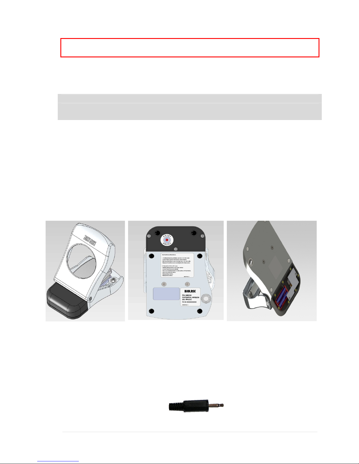
Wireless Footswitch
The EPIC 10 will not emit laser energy until the user presses down on the footswitch in
READY mode. The footswitch is designed to work using wireless technology. Two AAA
batteries are required to power the footswitch (operating voltage – 2 to 3.2 volts).
Figure 3: Footswitch
Remote Interlock
This feature allows the device to be connected to the remote sensor which will prevent
its operation when triggered (e.g., by opening door). The electric cable from this
connector should be wired to the normally closed switch, sensing the opening of a door
and turning the laser OFF when switch is open.
This feature is overridden when the plug is not connected.
Figure 4: Remote Interlock connector

10 | Page 5400321Rev. X: DRAFT
Emergency Stop
Press the red Emergency Laser Stop button to instantly turn off the unit. The error
screen will display an “Emergency Switch Error” message. Press the “√” icon to clear
the error and automatically set the system into STANDBY mode.
Figure 5: Emergency Laser Stop
Functional Display
The System Color Display with Touch Screen and LED indicators on the control panel
show the functional conditions of the system.
Safety Classification
The following safety classifications are applicable to the device:
Laser Radiation – Class 4
Type of protections against electrical shock – Class 1
Degree of protection against electrical shock – Type B Applied Part
Not protected against water ingress – Ordinary Equipment
Not suitable for use in presence of flammable anesthetic mixture
Operation Mode – Continuous Operation
Wireless Footswitch – IPX6

11 | Page 5400321Rev. X: DRAFT
S
ection 3: EQUIPMENT DESCRIPTION
General
The EPIC 10 system consists of three components:
Console
Delivery System
Wireless Footswitch
Base Console
The Console has a Display Panel (Touch Screen and Control Button) in front. It can be
powered by an external mains power supply or an internal replaceablelithium ion battery
pack, 14.8V, 2.9 A/h
Control Panel (See Figure 7)
ITEM # ITEM ITEM DESCRIPTION
1CONTROL BUTTON (a) Turns the controls and display on and off
Places unit into STANDBY or READY mode
2LED INDICATOR (b)
Amber indicates unit is in STANDBY or
READY mode.
Blinking green indicates emission of laser
power.
Blinking blue indicates wireless connection is
active
Figure 7: Control Panel
(a)
(b)
(b)

12 | Page 5400321Rev. X: DRAFT
Main Menu and Procedures Screen (See Figure 8)
ITEM
#ITEM ITEM DESCRIPTION
1HOME Selects procedure categories
2PROCEDURES SCREEN Selects pre-set procedures parameters
Figure 8: Main Menu and Procedures Screen
Figure 9: Left Side View

13 | Page 5400321Rev. X: DRAFT
Figure 10: Right Side View
Figure 10: Back View
Figure 12: Front View
14 | Page 5400321Rev. X: DRAFT
Re-usable Surgical Delivery System
NOTE: All fiber optic cables, handpieces & tips are shipped non-sterile.
The EPIC 10 Re-Useable Delivery System with surgical handpiece consists of:
Re-Useable Fiber Optic Assembly
Surgical Handpiece (Figures 13, 14)
Disposable Tips (See Figures 15, 16, 17)
NOTE: The fiber optic cable is detachable from the console. The Handpiece is a
reusable accessory. The Handpiece will require cleaning and sterilization
prior to each patient treatment. Tips are intended for single-use only and
must be disposed of after each patient use. Proper tip disposal in a
biohazard medical waste sharps container is required. Tips must be
steam sterilized prior to use.
For instructions on cleaning and sterilization of the handpiece and tips
Refer to Section 8.
Fiber Optic Connection
The fiber optic cable is attached to the console by inserting the optical access plug
(Figure 13) into the optical access port (Figure 14).
For storage, the cable can be wound in the fiber storage channel around the base of the
console in either a clockwise or counterclockwise direction (Figure 15).
Figure 13: Optical Access Plug Figure 14: Optical Access Port

15 | Page 5400321Rev. X: DRAFT
Figure 15: Fiber Storage Channel
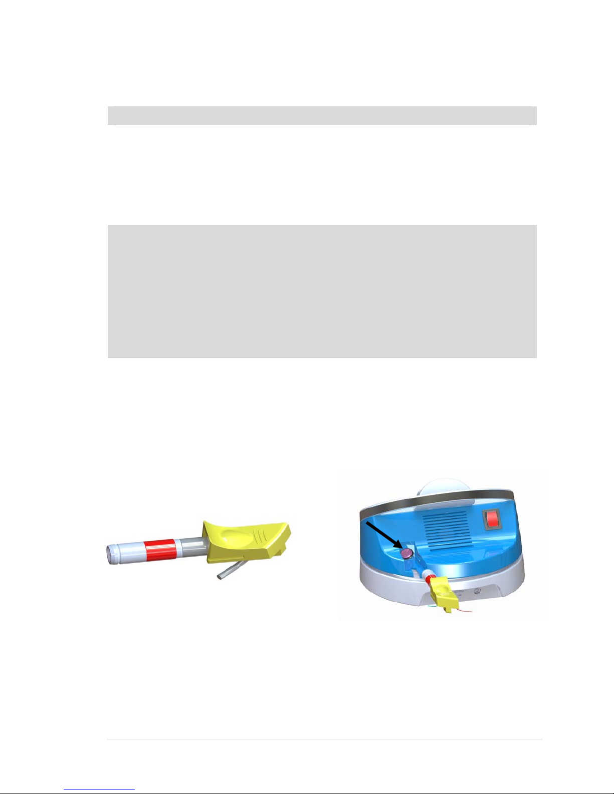
Single-use Tips
The tips are single-use accessories, which are provided in three core diameters:
200m, 300m and 400m and different lengths (see Appendix B).
WARNING: Always autoclave before tip initiation. Do not autoclave more than
once. Tips are single-use only.
To connect the tip, insert it into the handpiece orifice and tighten by turning
clockwise. Bend the metal cannula according to the specific procedure requirements.
NOTE: To provide proper laser operation, do not connect tips when the
handpiece is disconnected.
CAUTION: Do not bend tips with sharp angle - it will break the tip (Figure 17). If the
red aiming beam is not present in READY mode - replace the tip.
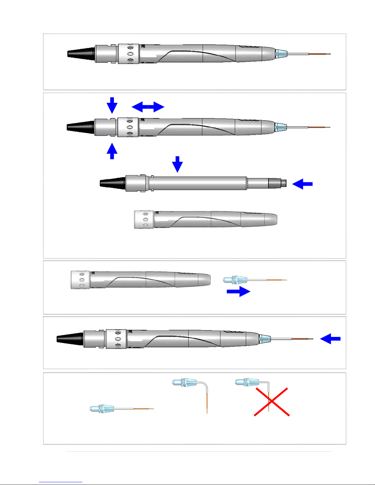
Surgical Handpiece Assembly
To connect the handpiece to the fiber optic assembly, push the handpiece on the
fiber shaft until it clicks on and is secured at connected position.
To disconnect handpiece from fiber optic assembly:
1. Take handpiece body in one hand and the shaft in another (See Figure 14)
2. Push two buttons on the handpiece shaft
3. Pull handpiece with the ring to separate.
16 | Page 5400321Rev. X: DRAFT
Figure 16: Surgical Handpiece Assembly
Fiber Shaft Protective Window
Handpiece
Figure 17: Disconnecting the Handpiece(push both buttons)
Tip assembly
Figure 18: Disconnecting the fiber Tip (twist first counter clockwise)
Figure 19: Tightening the fiber tips twist (only when Handpiece is connected to fiber)
Bend Correct Incorrect
Figure 20: Bending the tip cannula
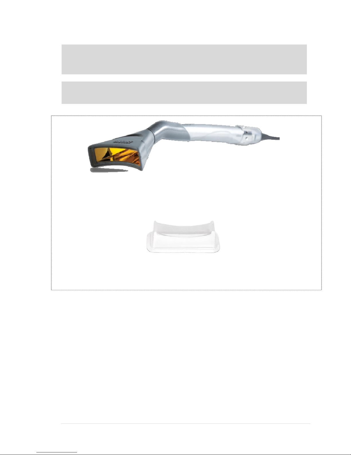
Whitening/Contour Handpiece
17 | Page 5400321Rev. X: DRAFT
NOTE: The handpiece is reusable and equipped with a disposable non-sterile
protective shield for single patient use. The handpiece requires cleaning
before and after each patient treatment. For instructions on cleaning the
the handpiece, refer to section 8.
NOTE: The Whitening/Contour Handpiece is compatible only with the Re-useable
Fiber Optic Cable Assembly. It is not compatible with the Classical
(Feed-Through) Fiber.
Whitening/Contour Handpiece
Disposable Shield
The area of Laser Energy Output is 35mm x 8mm = 2.8cm2Spot Size.
To disconnect the handpiece from the fiber optic assembly:
1. Take the handpiece body in one hand and the shaft in another.
2. Push two buttons on the handpiece shaft.
3. Pull handpiece with the ring to separate.
To connect the Handpiece to the fiber optic cable, push the handpiece on the fiber shaft
until it clicks on and is secured.
Deep Tissue Handpiece (Optional)

18 | Page 5400321Rev. X: DRAFT
NOTE: The handpiece is reusable and equipped with a disposable non-sterile
protective shield for single patient use. The handpiece requires cleaning
before and after each patient treatment. For instructions on cleaning the
the handpiece, refer to section 8.
NOTE: The Deep Tissue Handpiece is compatible only with the Re-useable Fiber
Optic Cable Assembly. It is not compatible with the Classical (Feed-
Through) Fiber.
Deep Tissue Handpiece
1) Remove Red Dust Cover from Deep Tissue Handpiece
2) Slide handpiece over monocoil shaft until it clicks
into place.
3) Place protective cover over the adjustable spacer
4) Loosen the Lock Ring and set the spacer at the desired spot size detent location.
Tighten the Lock Ring.
5) Place handpiece into the handpiece holder.
To remove handpiece, press and hold the buttons on the side of the shaft and pull
handpiece away from shaft.
Classical “Feed-Through” Fiber Handpiece (Optional)
19 | Page 5400321Rev. X: DRAFT
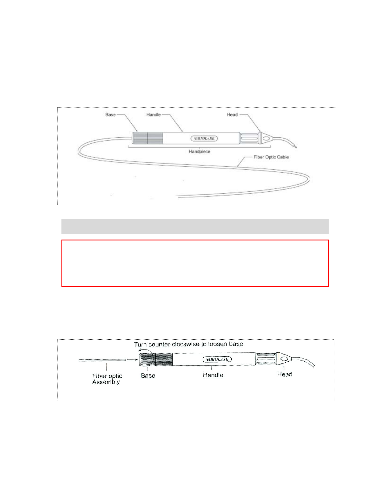
Classical “Feed-Through” Delivery System
The Feed-Through Delivery System with Surgical Handpiece consists of a Fiber Optic
Assembly with the following:
►Handpiece
►Base
►Handle
►Head (30°)
NOTE: The standard fiber optic cable assembly is a 400µm fiber. Other sizes are
available upon request.
WARNING: All fiber optic cables, handpieces, and heads are shipped non-sterile.
These are reusable accessories that require cleaning and sterilization
before and after each patient treatment. For instructions on cleaning
and sterilization of the fiber optic cable, handpiece, and head, refer to
Section 8. Fiber optic cable is not autoclavable unless it is labeled as
“autoclavable.”
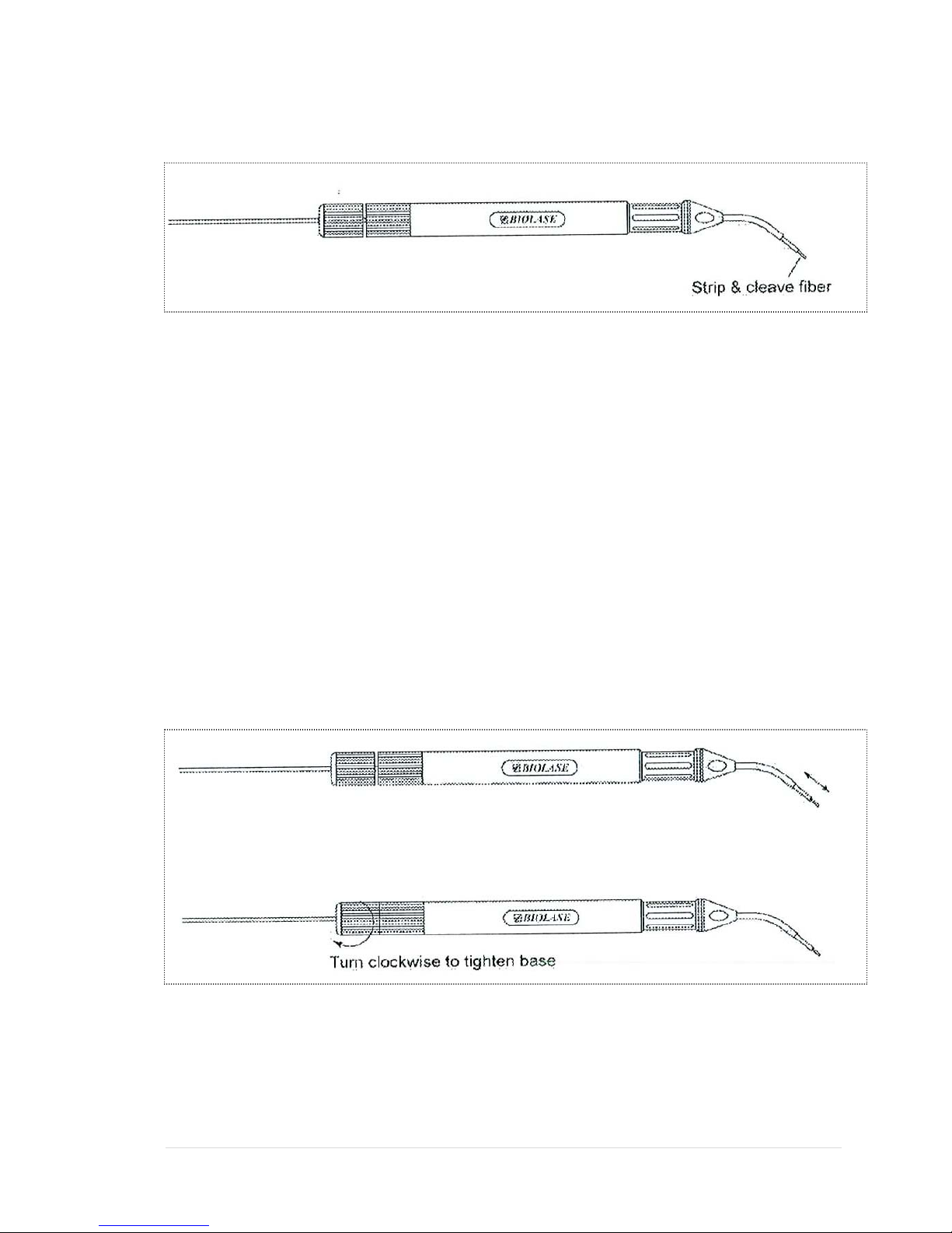
Cleaving the Fiber
The fiber should be cleaved after each procedure.
1) Loosen the proximal end of the handpiece by unscrewing the handpiece base.
2) Pull 2-3 inches of fiber optic cable from the handpiece head through the handpiece.
3) Select a fiber stripper that corresponds to the fiber diameter size.
4) Insert approximately 1 inch of the fiber optic cable into the stripper. Squeeze the
stripper handles to get a firm purchase on the fiber optic cable, and while doing so pull
20 | Page 5400321Rev. X: DRAFT
the stripper away from the handpiece in a smooth motion to ensure that the jacket is
cleanly removed.
5) Use a diamond/carbide cleaver to cut the used end of the fiber. Place the fiber
against a flat surface. Position the edge of the cleaver approximately ¼ inch from the
end of the fiber, and make a scratch around half the circumference of the fiber. Make
sure that the edge of the cleaver is always perpendicular to the fiber during
scratching.
6) Hold the end of the fiber above the scratch between thumb and forefinger and pull the
end of the fiber away until the end section breaks off. If the fiber end is removed
properly by pulling in the direction perpendicular to the end surface of the fiber, the
fiber should end in a flat surface.
7) Verify the cleave quality by aiming the fiber at a flat surface and observing the shape
of the spot created by the visible aiming beam. If the visible spot is a full circle, then
the power output is optimal; if the circle is distorted, then repeat only the cleaving
procedure presented in steps 5 and 6 until you obtain a perfect circle beam.
8) After the fiber is successfully cleaved, pull the fiber back through the handpiece until
just the fiber tip protrudes from the fiber end of the handpiece head. Tighten the
handpiece base until snug. Ensure that the fiber isn’t loose by pulling tightly on the
fiber optic cable at the proximal end.
Tip Initiation: Parameters and procedures
Other manuals for epic 10
3
Table of contents
Other Biolase Medical Equipment manuals


Popular Medical Equipment manuals by other brands


Canta
Canta V Series USER GUIDE AND MAINTENANCE

Abbott
Abbott St. Jude Medical Patient Controller 3875 user guide

Physio Control
Physio Control LIFEPAK 12 Cleaning and sterilization manual

Argon Medical Devices
Argon Medical Devices SKATER manual

human care
human care NSB-400-S user manual

Otto Bock
Otto Bock 17LK3 Series Instructions for use