Bioness bioventus StimRouter Neuromodulation System User manual
LBL-000706
602-00725-001 Rev. A
08/2022
©2022 Bioventus LLC
Bioventus and the Bioventus logo are registered trademarks of Bioventus LLC.
StimRouter and Bioness are trademarks of Bioness Inc. | StimRouter.com
Bioness Inc.
25103 Rye Canyon Loop
Valencia, CA 91355
USA
Telephone: (800) 211-9136 or (661) 362-4850
Website: StimRouter.com
Rx Only
Clinician’s Guide
Labeling LBL-000706 [A] RELEASED
Environmental Policy
Service personnel are advised that when changing any part of the StimRouter system,
care should be taken to dispose of those parts in the correct manner; where applicable,
parts should be recycled. When the life cycle of a StimRouter component has been
completed, the product should be discarded according to the laws and regulations of the local
authority. For more information regarding these recommended procedures, please contact
Customer Service. Bioventus is committed to continuously seeking and implementing the best
possible manufacturing procedures and servicing routines.
Bioness Inc.
25103 Rye Canyon Loop
Valencia, CA 91355 USA
Telephone: (800) 211-9136 or (661) 362-4850
Website: StimRouter.com
Labeling LBL-000706 [A] RELEASED

IV
Table of Contents
Chapter 1: Introduction ........................................................................ 1
Chapter 2: Patient Components .......................................................... 3
StimRouter Lead ............................................................................................... 3
StimRouter External Electric Field Conductor (E-EFC) ...................................... 3
Charging Socket and Charging Light ............................................................ 3
Gel Electrode ..................................................................................................... 4
Chapter 3: StimRouter Clinician Kit .................................................... 7
Chapter 4: Warnings and Cautions .................................................... 9
Indications for Use ............................................................................................. 9
Device Use and Stability..................................................................................... 9
Device Materials................................................................................................. 9
Essential Performance ..................................................................................... 10
Contraindications ............................................................................................ 10
Warnings ......................................................................................................... 10
Magnetic Resonance Imaging (MRI) Safety Information ............................ 11
Pregnancy ....................................................................................................... 11
Programming .................................................................................................. 11
Flammable Fuel, Chemicals or Environment .................................................. 11
Driving and Operating Machinery ................................................................... 11
Electromagnetic Compatibility Warnings ........................................................ 12
Medical Devices/Therapies ........................................................................ 12
Electrosurgery Devices .............................................................................. 12
High-Frequency Surgical Equipment ......................................................... 12
Body-Worn Devices ................................................................................... 13
Security Screening Devices ....................................................................... 13
Cell Phones ................................................................................................ 13
Precautions ..................................................................................................... 13
Post-Operative Care .................................................................................. 13
Known or Suspected Heart Problems ........................................................ 14
Implant Failure ............................................................................................. 14
Postural Changes ....................................................................................... 14
For Single Use Only ................................................................................... 14
Keep Out of Reach of Children .................................................................. 14
List of Symbols
Caution
Warning
Class II Equipment (Double Insulated)
Type BF Applied Part(s)
Non-Ionizing Radiation
Date of Manufacture
Manufacturer
This Product Must Not Be Disposed of with Other Household Waste
Refer to Instruction Manual/Booklet
Consult Instructions for Use
Re-Order Number
Lot Number
Serial Number
Single Patient Multiple Use
MR Conditional
Single Use
Storage Temperature
Humidity Limitation
Atmospheric Pressure Limitation
IP68 Protection Against Ingress of Water
Keep Dry
Use By
Quantity
Prescription Only
MD Medical Device
Labeling LBL-000706 [A] RELEASED

VI
VClinician’s Guide
Skin Abnormalities ..................................................................................... 14
Skin Irritation .............................................................................................. 14
Sensations Caused by Stimulation ............................................................ 15
Gel Electrode Expiration Date .................................................................... 15
Gel Electrode Placement and Stimulation .................................................. 15
Adverse Effects .............................................................................................. 16
Risks Related to the Implant Procedure ..................................................... 16
Risks Related to Stimulation ...................................................................... 16
Additional Risks Related to the StimRouter System .................................. 16
Temperature ................................................................................................... 17
End-Of-Life Waste Management...................................................................... 17
Chapter 5: Environmental Conditions that Affect Use .................... 19
Storage and Handling ..................................................................................... 19
Radio Communication Information ................................................................. 19
Conformity Certification .............................................................................. 20
Chapter 6: Device Description .......................................................... 21
Clinician’s Programmer .................................................................................. 21
Operating Buttons ...................................................................................... 21
Micro SD Slot ............................................................................................ 21
Touchscreen Display .................................................................................. 21
Clinician’s Programmer Micro SD Card ..................................................... 21
Clinician’s Programmer Charger ................................................................ 22
StimRouter Plus Software .............................................................................. 22
Operating Modes ........................................................................................ 22
Online ................................................................................................... 22
Offline ................................................................................................... 22
Information Icon ......................................................................................... 23
Drop-Down Lists ........................................................................................ 24
Menu Bars and Menus ............................................................................... 24
Exit ....................................................................................................... 24
Patients ................................................................................................ 24
Programs .............................................................................................. 24
Tools .................................................................................................... 24
Tabs ........................................................................................................... 24
Navigation Buttons ..................................................................................... 26
Intensity Level Bar ...................................................................................... 27
Program Bar ............................................................................................... 27
Add Program Icon ................................................................................ 27
Delete Program Icon ............................................................................ 27
Program Bar Arrows ............................................................................. 27
Stimulation Parameters .............................................................................. 27
Chapter 7: Clinician’s Programmer Set-up ...................................... 31
Connecting the Clinician’s Programmer ......................................................... 31
Logging into the StimRouter Plus Software .................................................... 32
Connecting E-EFC via Bluetooth .................................................................... 32
Chapter 8: Software Records and History ....................................... 35
Patient Records .............................................................................................. 35
Adding a New Patient ................................................................................. 35
Copying a Record for an Existing Patient to an Unassigned System ........ 36
Adding a Patient with an Assigned System ................................................ 37
Opening a Patient Record .......................................................................... 37
Modifying a Patient Record ........................................................................ 38
Removing a Patient Record ....................................................................... 39
Searching for a Patient Record .................................................................. 39
History ........................................................................................................ 40
View Usage History .................................................................................... 40
Select a Stimulation Program ..................................................................... 40
Select a Time Period .................................................................................. 40
Select Duration ........................................................................................... 41
Select Intensity ........................................................................................... 41
Change Date Ranges ................................................................................. 41
View Sessions History ................................................................................ 42
Save Usage Data ....................................................................................... 42
Chapter 9: Patient Set-Up and Programming Instructions ............. 43
Preparing the Patient’s Skin ........................................................................... 43
Connecting the Gel Electrode and E-EFC ...................................................... 43
Adhering the Gel Electrode to the Skin .......................................................... 44
Confirming Set-Up .......................................................................................... 46
Removing the Gel Electrode ........................................................................... 46
Programming Instructions ............................................................................... 47
Programming Stimulation Settings ............................................................. 47
Programming Time Settings ....................................................................... 48
Labeling LBL-000706 [A] RELEASED

VIII
VII Clinician’s Guide
Guidance and Manufacturer’s Declaration Electromagnetic Emissions ..... 69
Guidance and Manufacturer’s Declaration Electromagnetic Immunity ...... 71
Recommended Separate Distances for Device ......................................... 74
Programs ........................................................................................................ 49
Adding a Program ..................................................................................... 49
Deleting a Program .................................................................................... 49
Chapter 10: Software Tools ............................................................... 51
Resetting the E-EFC ....................................................................................... 51
Restart the E-EFC from the E-EFC Buttons ................................................... 51
User Administration ........................................................................................ 51
Adding a User/Administrator ...................................................................... 52
Removing a User/Administrator ................................................................. 53
Changing a User Password ....................................................................... 53
Clinician’s Programmer Database Backup and Restore ................................ 53
Enabling Automatic Database Backup ....................................................... 54
Manually Backing Up the Database ........................................................... 54
Restoring the Database ............................................................................. 54
Chapter 11: Maintenance and Cleaning ........................................... 57
Replacing Gel Electrode ................................................................................. 57
Cleaning ......................................................................................................... 57
Disinfecting ..................................................................................................... 58
Electronic Components .............................................................................. 58
Chapter 12: Troubleshooting ............................................................ 59
Patient Forgets E-EFC ................................................................................... 59
Patient Loses E-EFC ...................................................................................... 59
Patient Brings New E-EFC ............................................................................. 59
Copying Patient Data to New Components ................................................ 59
Troubleshooting Tables .................................................................................. 60
Incident Reporting ............................................................................................ 61
Chapter 13: Technical Specifications ............................................... 63
E-EFC Charger Specifications ........................................................................ 63
E-EFC Specifications ...................................................................................... 63
Gel Electrode Specifications ........................................................................... 65
System Characteristics..................................................................................... 65
Privacy of StimRouter Wireless Communication ............................................. 66
Chapter 14: Network Safety, Security, and Privacy ........................ 67
Chapter 15: Appendix - EMI Tables .................................................. 69
Electromagnetic Emissions ............................................................................ 69
Labeling LBL-000706 [A] RELEASED

Chapter 1 - Introduction 1
1
IX Clinician’s Guide
Introduction
The StimRouter Neuromodulation System is intended to help relieve chronic pain
of peripheral origin. The StimRouter Neuromodulation System is made up of
implanted components from the StimRouter Implantable Lead and Lead Introducer
Kit (ST2-1000) and external components from the StimRouter User Kit (ST2-
5050). Additional components from the StimRouter Clincian Kit (ST2-4050) are
also referenced in this guide. The StimRouter System consists of the following:
• A StimRouter lead
• A clinician programming system with a Clinician’s Programmer and
charger, Programming software, Programmer Connector Cable, a Tester
and accessories
• A rechargeable External Electric Field Conductor (E-EFC), charger, and
accessories
• A Gel Electrode
This guide describes the clinician programming system components of the StimRouter
Neuromodulation System, which are provided in the StimRouter Clinician Kit. The
clinician programming components are used by trained clinicians to program the
patient’s E-EFC. The E-EFC and other external components are intended to be
operated by patients.
Refer to the StimRouter Procedure Manual for a description of the StimRouter
Implantable Lead and Lead Introducer Kit, package contents, device specifications
and the StimRouter implant procedure.
Refer to the StimRouter User’s Guide for a full description of the StimRouter
User Kit, Gel Electrode, E-EFC, external accessories, package contents, device
specifications, and instructions for use.
Labeling LBL-000706 [A] RELEASED

Chapter 2 - Patient Components 3
2
2Clinician’s Guide
Patient Components
StimRouter Lead
The StimRouter Lead is flexible and approximately 15 cm (6 in.) in length. The
lead has a stimulation end and a receiver end. The lead implantation places the
stimulation end near or at the targeted peripheral nerve. The receiver end of the
StimRouter lead receives the signal from the E-EFC and conducts the stimulation
pulse through the lead to the stimulation end. See Figure 2-1.
Figure 2-1: The StimRouter Lead
StimRouter External Electric Field Conductor (E-EFC)
The StimRouter E-EFC generates the transcutaneous signal and transmits the
signal via the Gel Electrode/Skin interface to the StimRouter lead. The E-EFC
snaps onto the Gel Electrode (See Figure 2-2) and responds to wireless commands
from the StimRouter Plus Mobile Application.
Figure 2-2: The E-EFC attached to the Gel Electrode
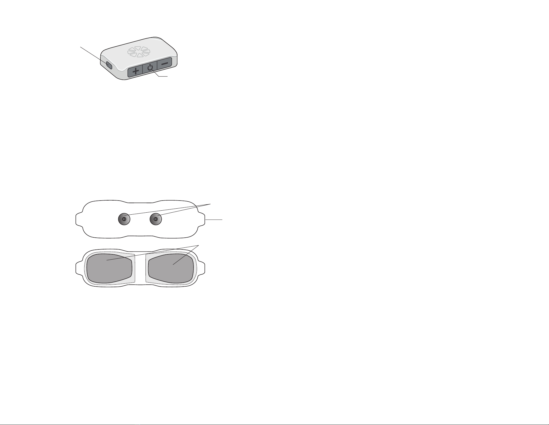
Charging Socket and Charging Light
The E-EFC charging socket is located on the front panel of the E-EFC. When
the E-EFC is charging a green charging light will appear on the side panel of the
E-EFC. See Figure 2-3.
E-EFC
Gel Electrode
Lead
Labeling LBL-000706 [A] RELEASED
Chapter 2 - Patient Components 54 Clinician’s Guide
Figure 2-3: The E-EFC charging socket and charging light location
Gel Electrode
Gel Electrode features: (See Figure 2-4)
• Two gel pads that adhere the Gel Electrode to the skin. The gel pads
also transmit the stimulation signal from the E-EFC to the receiver end of
the lead.
• Two snaps for E-EFC placement.
• Two tabs for removing the Gel Electrode from the skin.
• A liner to protect the gel pads on the back of the Gel Electrode.
Figure 2-4: Gel Electrode (top and bottom views)
The Gel Electrode is disposable and can be reused by the same patient as long
as the gel pads are intact and can fully adhere to the skin or for a maximum of
four days of use.
The typical lifespan of the Gel Electrode is two to four days, depending on:
• The number of hours of use.
• The number of times the Gel Electrode is adhered and removed from the
skin.
• Hygiene and skin care in the area of Gel Electrode placement.
Gel Pads
Snaps
Tabs
E-EFC Charging Socket
Location of Charging Light
Labeling LBL-000706 [A] RELEASED
3
Chapter 3 - StimRouter Clinician Kit 76 Clinician’s Guide
StimRouter Clinician Kit
The StimRouter Clinician Kit includes the following:
• Clinician’s Programmer, Tablet with Software and Stylus
• Clinician’s Programmer Micro SD Card
• Clinician’s Programmer Charger
Clinician’s Programmer
Labeling LBL-000706 [A] RELEASED

4
Chapter 4 - Warnings and Cautions 98 Clinician’s Guide
Warnings and Cautions
Use the StimRouter system only as instructed in the User’s Guide.
Indications for Use
The StimRouter Neuromodulation System is indicated for pain management in
adults who have severe, intractable chronic pain of peripheral nerve origin, as
an adjunct to other modes of therapy (e.g., medications). The StimRouter is not
intended to treat pain in the craniofacial region.
Device Use and Suitability
The StimRouter Neuromodulation System is designed to reduce pain in patients with
chronic pain of peripheral nerve origin. Components of the StimRouter Implantable
Lead and Lead Introducer Kit and StimRouter Clinician Kit are for use by trained
clinicians, and components of the StimRouter User Kit are for use by individual
patients. Additional information, including clinical safety and performance, can be
found at www.StimRouter.com.
The StimRouter Neuromodulation System may not be suitable for treatment of
acute pain, for pain that is not of peripheral nerve origin, or for patients whose
required stimulation parameters cannot be met by the StimRouter Neuromodulation
System. The StimRouter Neuromodulation System implant procedure may be
performed in any sterile surgical setting.
Device Materials
Materials in the StimRouter User Kit that may contact the patient during device
use include:
• Hydrogel
• Plastic
Both materials have been tested to verify biocompatbility.
Labeling LBL-000706 [A] RELEASED

Chapter 4 - Warnings and Cautions 1110 Clinician’s Guide
occur during diathermy treatment whether neurostimulation is turned on
or off. All patients are advised to inform their health-care professionals
that they should not be exposed to diathermy.
• Patients exposed to therapeutic ultrasound.
Magnetic Resonance Imaging (MRI) Safety Information
The StimRouter Neuromodulation System is MR Conditional. A person implanted
with this device can be safely scanned with MRI only under very specific conditions.
Scanning under different conditions may result in severe injury or device malfunction.
Full MRI safety information is available in the MRI Guidelines Manual, which can
be obtained at StimRouter.com or by calling 800-211-9136. An MRI examination
of a patient with a StimRouter Neuromodulation System should not be conducted
until the information in the Clinician’s Guide and MRI Guidelines is read and
understood.
All external components of the StimRouter system, including the Gel Electrode,
E-EFC, Clinician’s Programmer, and Clinician’s Programmer Charger are MR
Unsafe and are contraindicated for the MR environment. Do not bring them into
the MR system room.
Pregnancy
The effects of electrical stimulation on pregnancy are not known. Do not use
electrical stimulation during pregnancy.
Programming
Only a trained clinician should program the StimRouter system.
Flammable Fuel, Chemicals or Environment
The StimRouter is not intended to be used in oxygen-rich environments.
Turn off stimulation when you are near a refueling station, flammable fuel, fumes
or chemicals. If your system is on, it could ignite the chemicals or fumes, causing
severe burns, injury or death.
Driving and Operating Machinery
Turn off stimulation while driving or operating machinery.
Essential Performance
The StimRouter System does not have Essential Performance as there is no
performance necessary (as defined by IEC 60601) to avoid unacceptable risks,
in that all sources of identified risk have been mitigated (through application
of appropriate risk control measures) to the greatest extent possible and to an
acceptable degree. There are no sources of residual risk which outweigh the
benefits accrued from the use of the device and which would thus be deemed
unacceptable.
Contraindications
The StimRouter is contraindicated for:
• Patients who are unable to operate the StimRouter Neuromodulation
System.
• Patients who are poor surgical candidates.
• Patients who have a cancerous lesion present near the target stimulation
point or near to where the Gel Electrode will adhere.
• Patients with bleeding disorders or active anticoagulation that cannot be
stopped for a few days close to the time of the surgical procedure.
• Patients who are unable to remove the E-EFC.
• Patients who are unable to communicate a device malfunction from
device use.
Warnings
• The StimRouter Neuromodulation System may interfere with other
implanted devices such as cardiac pacemakers, defibrillators, and other
implanted stimulators. The effect of other implanted devices, including
but not limited to implanted drug pumps and other stimulation devices on
the StimRouter Neuromodulation System is unknown.
A risk/benefit determination should be performed before using the StimRouter
Neuromodulation System for:
• Patients exposed to diathermy. Shortwave, microwave and/ or
therapeutic ultrasound diathermy should not be used on patients who
have a StimRouter Neuromodulation System. The energy generated
by diathermy can be transferred through the StimRouter system
components, causing tissue damage at the lead site and potentially
resulting in severe injury. Diathermy may also damage the StimRouter
system components, resulting in loss of therapy. Injury or damage can
Labeling LBL-000706 [A] RELEASED

Chapter 4 - Warnings and Cautions 1312 Clinician’s Guide
Body-Worn Devices
Although unlikely, body-worn medical devices may interfere with the RF
communication used in the StimRouter system. Stimulation control may be delayed.
Examples of a body- worn device are a pain pump or an insulin pump and a
monitoring device. To minimize interference, maintain a minimum safe separation
distance of 15 cm (6 in.) between the StimRouter system and all other electronic
devices. See the “Troubleshooting” section for help. See the “Appendix” for more
information.
The StimRouter system’s wireless technology may cause EMI to other body-worn
medical devices. Refer to the instructions for use for those devices for information
on recommended minimum separation distances.
Security Screening Devices
Certain types of security devices may affect stimulation. Examples include those
used at the entrances and exits of public buildings such as libraries, airports and
retail stores. A patient should ask for help to bypass the device. The Medical
Device Identification Card can be shown. If a patient must pass through the device:
• Turn off your StimRouter system.
• Pass through the security screening device quickly.
• Stay as far from the emitter as possible. Walk, for example, in the center
of a pass-through security gate.
Cell Phones
There is potential for interference between electronic devices, including cell
phones. Stimulation control may be delayed. If interference is suspected or
anticipated, distance yourself from the source of interference. To minimize
interference, maintain a minimum safe separation distance of 15 cm (6 in.)
between the StimRouter system and all other electronic devices.
Precautions
Post-Operative Care
After the implant procedure, the incision site should be checked for infection,
possible device rejection or other possible adverse effects.
A patient should contact you immediately if they have:
• Excessive redness or discharge around the incision site.
• Prolonged pain at the incision site.
Electromagnetic Compatibility Warnings
Medical Devices/Therapies
Operation of the StimRouter system in close proximity (e.g., 1 meter or 3 feet) to
shortwave or microwave therapy equipment may produce instability in the E-EFC
output.
The following medical therapies or procedures may turn stimulation off. They may
also permanently damage the StimRouter external components and may cause
injury, particularly if used close to the system components.
• Lithotripsy
• Electrocautery
• External defibrillation
• Ultrasonic scanning
• High-output ultrasound
Electromagnetic interference (EMI) from the following medical procedures is unlikely
to affect the StimRouter system:
• Computerized Axial Tomography (CT or CAT) scans
• Diagnostic ultrasound (e.g., carotid scan, Doppler studies)
• Diagnostic x-rays or fluoroscopy
Note: Turn off stimulation and remove the Gel Electrode before undergoing a
medical procedure.
Electrosurgery Devices
Electrosurgery devices should not be used close to an implanted StimRouter
Neuromodulation System. Contact between an active electrode of the electrosurgery
device and the StimRouter Neuromodulation System can stimulate the receiver
and cause severe injury.
High-Frequency Surgical Equipment
Remove the Gel Electrode before medical treatment. If the patient is connected to
the StimRouter system and high-frequency surgical equipment, they may experience
a skin burn where the Gel Electrodes adhere. Also, the StimRouter E-EFC may
become damaged.
Labeling LBL-000706 [A] RELEASED

Chapter 4 - Warnings and Cautions 1514 Clinician’s Guide
irritation, remove the Gel Electrode every three to four hours for 15 minutes.
Sensations Caused by Stimulation
As with other nerve stimulation devices, the StimRouter Neuromodulation achieves
pain relief by causing different sensations to be felt in the area of treatment. These
sensations (also referred to as “paresthesia”) include tingling and numbness.
While these sensations are normal during StimRouter use, stimulation should not
proceed to the point of being painful.
Gel Electrode Expiration Date
Do not use a Gel Electrode with a “Use by” date that has expired.
Gel Electrode Placement and Stimulation
• Only use Gel Electrodes supplied by Bioventus
• Only the doctor should decide where to place the Gel Electrode.
• Only the doctor should program the StimRouter system.
• Turn off stimulation before adhering, removing or handling the Gel
Electrode.
• Do not adhere the Gel Electrode across the chest or near the heart.
Electrical stimulation of the heart may disturb heart rhythm.
• Avoid placing the Gel Electrode across the head, directly on the eyes,
covering the mouth, or on the front of the neck, (especially the carotid
sinus).
• Do not adhere the Gel Electrode over anything other than skin. Do not
adhere it over an adhesive bandage, for example. The Gel Electrode
must be in full contact with the skin or the stimulation could cause
serious injury.
• Do not place the Gel Electrode over skin folds, scarred tissue, irritated
skin, uneven skin surfaces or broken skin.
• Always check the Gel Electrode gel pads before use. Do not use the Gel
Electrode if the gel appears dry, worn, dirty or irregular.
• Remove the clear protective cover from the Gel Electrode before using.
• Do not handle the Gel Electrode with both hands while stimulation is on.
Serious injury can occur if electrical current passes through the heart.
• Patient must be instructed to not apply the Gel Electrode to anyone else
or any other part of the body than that determined by the doctor.
• Warmth and swelling of the incision site.
• Fever
• Dizziness
• Bleeding
Known or Suspected Heart Problems
Caution should be used when treating patients with suspected or diagnosed heart
problems.
Implant Failure
Implanted receivers may fail at any time. If a StimRouter fails or breaks, then the
StimRouter system may need to be removed or replaced. It is possible that small
fragments of the lead could remain at the implantation site after removal, which
will indefinitely prevent the patient from being eligible for certain procedures, such
as diathermy, therapeutic ultrasound, or MRI in the affected area. A patient should
contact you immediately if implant failure is suspected.
Postural Changes
Changes in posture or abrupt movements may change the stimulation that is felt.
Turn off stimulation before stretching or exercising.
For Single Patient Use Only
Do not adhere the Gel Electrode to any other person.
Keep Out of Reach of Children
Keep all StimRouter components out of the reach of children.
Skin Abnormalities
Do not adhere the Gel Electrode to skin that is swollen, infected or inflamed or to
skin that is broken. Do not adhere the Gel Electrode over veins that are swollen
or inflamed.
Skin Irritation
It is normal for the skin under the Gel Electrode to become red. The redness
should disappear about one hour after the Gel Electrode is removed.
Some people may be allergic or hypersensitive to the electrical stimulation or
the gel on the Gel Electrode. Persistent redness, lesions or blisters are signs of
irritation. Stop using the StimRouter system until the irritation is gone. To avoid
Labeling LBL-000706 [A] RELEASED

Chapter 4 - Warnings and Cautions 1716 Clinician’s Guide
Adverse Effects
In the unlikely event that any of the following occurs, the StimRouter system should
be stopped and the Gel Electrode removed.
Risks Related to the Implant Procedure
If the lead is not placed properly, it may need to be removed or the therapy may
need to be adjusted. Nerve injury is possible, although unlikely. Possible surgical
complications include infection and device rejection. A patient should contact you
immediately if they experience fever, swelling, bleeding or prolonged pain at the
implant site.
Risks Related to Stimulation
• Stimulation of skin and muscles surrounding the lead may cause
increased pain.
• A patient may have undesirable movements during stimulation.
If a patient experiences any discomfort during stimulation, or notice any
skin abnormalities they should:
• Stop stimulation immediately.
• Remove the Gel Electrode.
• Notify you.
Additional Risks Related to the StimRouter System
• If the lead moves, it may change the stimulation effectiveness.
• While very unlikely, the tissue around the lead may react to the
implanted materials.
• External electromagnetic interference (EMI) may cause the StimRouter
components to malfunction. EMI may also affect stimulation.
• Persistent pain may occur at the implant site.
• Although rare, the skin overlying the lead may erode.
• Portable and mobile radio frequency communications equipment can
affect medical electrical equipment.
• The StimRouter external components could overheat if the components
fail. Overheating could cause burning.
Temperature
The StimRouter E-EFC can heat up to 43°C during operation in extremely hot
areas/rooms. If this occurs turn off stimulation, remove E-EFC, and set aside until
temperature is within operational conditions.
End-Of-Life Waste Management
WEEE Regulations place an obligation on distributors to offer consumers a take-
back system where WEEE items can be disposed of free of charge.
Labeling LBL-000706 [A] RELEASED

5
Chapter 5 - Environmental Conditions that Affect Use 1918 Clinician’s Guide
Environmental Conditions
that Affect Use
Storage and Handling
All StimRouter components should be kept dry and protected from extreme changes
in temperature and humidity. Components should not be used or stored where they
could come in contact with water, such as by sinks, bathtubs and shower stalls, or
expose them to weather conditions such as rain or snow. StimRouter components
should not be stored in a car where they can be exposed to extreme hot or cold
temperatures. Temperature extremes can damage the StimRouter components.
To avoid condensation when transporting StimRouter components from hot to
cold temperatures, the components should be placed in an air-tight plastic bag
first and be allowed to adjust slowly (for at least two hours) to the change in
temperature before use.
Radio Communication Information
Several components of the StimRouter system communicate via radio communication
and have been tested and found to comply with the limits for a Class B digital
device, pursuant to Part 15 (Radio Frequency Devices) of the FCC Rules. These
limits are designed to provide reasonable protection against harmful interference
in a residential environment. This equipment generates, uses and can radiate
radio frequency energy and, if not operated and used in accordance with the
instructions, may cause harmful interference to radio communications. However,
there is no guarantee that interference will not occur in a particular environment.
If this equipment does cause harmful interference to radio or television reception,
which can be determined by turning the equipment off and on, then try to correct
the interference by one or more of the following measures:
• Reorient or relocate the receiving antenna.
• Increase the separation between the equipment and receiver.
• Consult the dealer or an experienced radio/television technician for
assistance.
The antenna for each transmitter must not be near to or operating with any other
antenna or transmitter.
Labeling LBL-000706 [A] RELEASED

6
Chapter 6 - Device Description 2120 Clinician’s Guide
Changes or modifications to components not expressly approved by Bioventus
could void the user’s authority to operate the equipment.
Conformity Certification
The StimRouter complies with Part 15 of the FCC Rules. Operation is subject to
the following two conditions:
1. This device may not cause harmful interference
2. This device must accept any interference received, including interference
that may cause undesired operation.
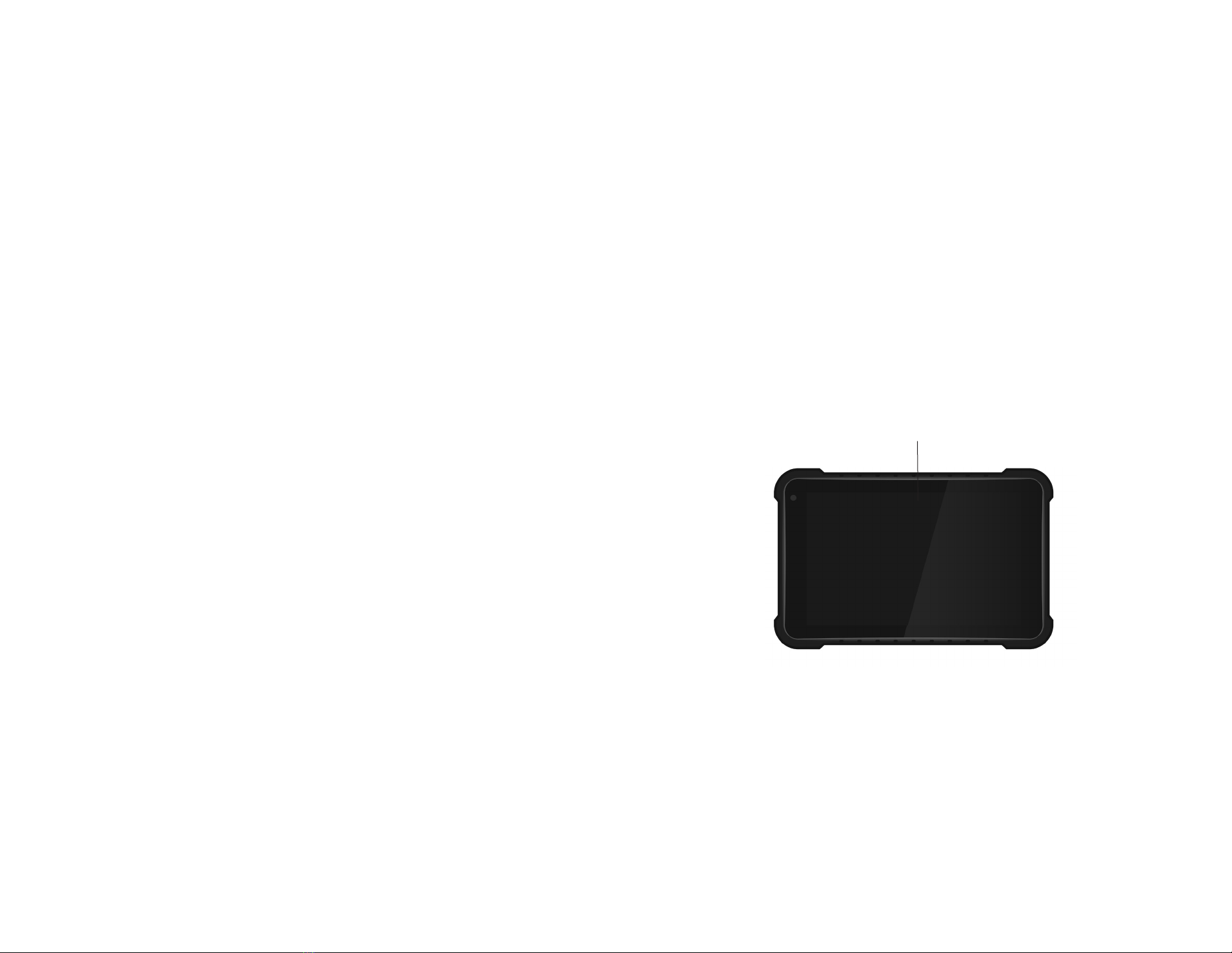
Device Description
Clinician’s Programmer
The StimRouter Clinician’s Programmer is used to program, test and save stimulation
parameters and programs on the StimRouter E-EFC. The Clinician’s Programmer
is a Windows®Tablet PC that comes with the StimRouter Plus software and a
memory card installed. The Clinician’s Programmer can wirelessly communicate
with the StimRouter E-EFC.
Operating Buttons
Buttons Description Function
Power Button Used to turn the Clinician’s
Programmer on and off
Volume Up Button Used to turn the Clinician Programmer
volume up
Volume Down
Button
Used to turn the Clinician Programmer
volume down
Micro SD Slot
Contains the Clinician’s Programmer micro SD card.
Touchscreen Display
Used to navigate the StimRouter Plus software, read status and enter data. Use
the pointed end of the stylus to make contact with the display screen.
Clinician’s Programmer Micro SD Card
Used to back up and restore the Clinician’s Programmer database. The micro SD
card is supplied installed in the SD slot of the Clinician’s Programmer.
Labeling LBL-000706 [A] RELEASED

2322 Clinician’s Guide Chapter 6 - Device Description
Operating Mode Function Descriptions
Online
• Add a new patient.
• Modify a patient name.
• Open a patient record.
• Program stimulation settings.
• Program time settings.
• Add or remove a stimulation program.
• View the system information.
• Reset the E-EFC.
• Back up the database.
• Restore the Clinician’s Programmer database.
• Add a new user.
• Remove a user.
• Change a user password.
Offline
• Add a new patient.
• Open any patient record.
• Remove a patient record.
• View a patient’s programs.
• Back up the Clinician’s Programmer database.
• Restore the Clinician’s Programmer database.
• Add a new user.
• Remove a user.
• Change a user password.
Table 6-1: StimRouter Plus software operating modes and function descriptions
Information Icon
Used to communicate system status, error messages and troubleshooting solutions.
When the icon is RED or YELLOW, press the icon for more information. See
Figure 6-1.
Figure 6-1: Location of the information icon
WARNING: The Clinician’s Programmer should only contain the installed
Windows®operating system and proprietary StimRouter Plus software.
• Do not use the Clinician’s Programmer for any purpose other than that
described in this manual.
• Do not connect the Clinician’s Programmer to Wifi or wired network.
• Do not install any third-party software packages, as they may interfere with
proper operation of the StimRouter components, thus voiding the warranty.
• Do not update the Windows operating system software, unless supplied by
Bioventus.
Clinician’s Programmer Charger
Used to recharge the Clinician’s Programmer.
WARNING: Use only the clinician’s Programmer Charger included in
StimRouter Clinician Kit.
StimRouter Plus Software
The StimRouter Plus software is provided installed on the Clinician’s Programmer.
Operating Modes
The StimRouter Plus software has two operating modes: online and offline.
Online. The StimRouter Clinician’s Programmer is online when connected to an
operational StimRouter E-EFC.
Offline. The StimRouter Clinician’s Programmer is offline when not connected to
an operational StimRouter E-EFC.
Information
Icon
Labeling LBL-000706 [A] RELEASED
2524 Clinician’s Guide Chapter 6 - Device Description
GREEN when the StimRouter is online and connected to an E-EFC;
GRAY when no E-EFC is detected.
FLASHING RED when a E-EFC is connected and a correctable error
has occurred (for example, RF communication failure).
FLASHING YELLOW when the StimRouter E-EFC battery charge level
is low.
Drop-Down Lists
Used to select a value. Press the down arrow to display the values. Select a value.
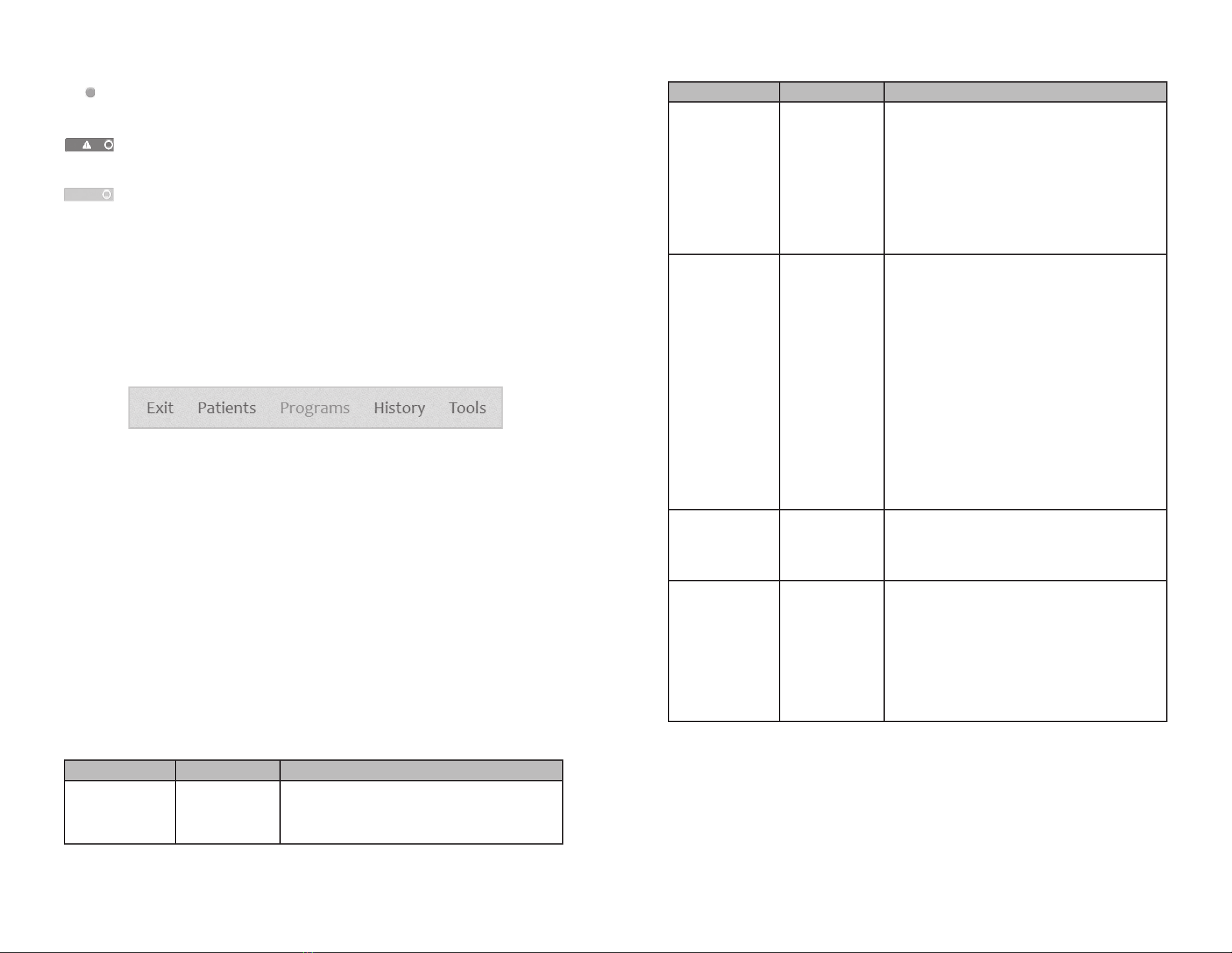
Menu Bar and Menus
The StimRouter Plus software has five navigation menus, which appear on the
menu bar. See Figure 6-2.
Figure 6-2: Menu bar
Exit. Used to exit or logoff the StimRouter Plus software.
Patients. Used to open a patient record, add a new patient, modify a patient
record or remove a patient record.
Programs. Used to program, test and save a set of stimulation and time settings.
(Enabled when a patient record is open.)
Tools. Used to view system information and to reset the E-EFC. Users with
administrator privileges can also add and remove users, change a user password,
and back up and restore the Clinician’s Programmer database.
Tabs
The StimRouter Plus software has eight navigation tabs, or submenus, found
under the five main menus. See Table 6-2.
Menu Tab Function Descriptions
Exit
• Exit the StimRouter Plus software.
• Log off the StimRouter Plus software.
Menu Tab Function Descriptions
Patients
• Open a patient record in online mode.
• Open any patient record in offline
mode.
• Remove a patient record in offline
mode.
• Add a new patient in online mode.
• Modify a patient name in online mode.
Programs Stim Settings • Program, test and save waveform,
phase duration, pulse rate and intensity
settings in online mode.
• Turn on Efficiency Mode feature.
• View stimulation settings for each
program saved.
• Add/delete programs in online mode.
Time
Settings
• Program, test and save time on, time
off, ramp up, total time and intensity
settings in online mode.
• View time settings for each program
saved.
• Add/delete programs in online mode.
Tools Info • View system information in online
mode.
• Reset the E-EFC in online mode.
Users • Add a new user.
• Remove a user.
• Change a user password.
Backup • Back up the Clinician’s Programmer
database.
• Enable/disable database backup.
Labeling LBL-000706 [A] RELEASED

2726 Clinician’s Guide Chapter 6 - Device Description
Intensity Level Bar
Used to adjust stimulation intensity. Can be adjusted while stimulation is on or
off. See Figure 6-3.
Figure 6-3: Intensity level bar
Program Bar
Used to add, delete and view up to eight clinician-set stimulation programs, labeled
A-H. See Figure 6-4.
Figure 6-4: Program bar and icon definitions
Add Program Icon. Used to add a new stimulation program. Enabled in online
mode when fewer than eight programs have been saved.
Delete Program Icon. Used to delete a stimulation program. Enabled in online
mode when more than one program has been saved.
Program Bar Arrows. Used to scroll through the saved programs. Enabled when
more than one program has been saved.
Stimulation Parameters
Patients require tailored stimulation patterns to help control their pain. The
StimRouter system features eight programmable parameters and can store up
to eight stimulation programs on the Clinician’s Programmer and E-EFC. Timing
parameters are specified in Table 6-4. Pulse parameters are specified in Table 6-5.
Menu Tab Function Descriptions
Restore • Restore the Clinician’s Programmer
database from backup.
Table 6-2: StimRouter Plus software navigation menus, navigation tabs
and functions that can be performed from each menu/tab
Navigation Buttons
When pressed, a navigation button will open a new screen or execute a command.
Depending on the operating mode, a button may be enabled or disabled. Disabled
buttons are GRAY. For a list of commonly used buttons, see Table 6-3.
Button Function Descriptions
Change Password • Change a user password (enabled for
administrators only).
Clear • Delete characters in a field.
Exit • Exit the StimRouter Plus software.
Login • Log into the StimRouter Plus software.
Log Off • Log off the StimRouter Plus software.
Modify • Modify an existing patient record.
New • Add a new patient record.
New User • Add a new user
(enabled for administrators only).
Open • Open an existing patient record.
Remove • Remove an existing patient record.
Remove User • Remove a user
(enabled for administrators only).
Reset the E-EFC
• Restore factory settings on the E-EFC. (When
selected, all patient data on the E-EFC is
erased.)
Stop & Save • Stop stimulation and save the stimulation and
time settings.
Test • Test the current stimulation and time settings.
Table 6-3: Selected navigation buttons and their accompanying functions
Increase 1 mA
Level Setting
Decrease 1 mA
Decrease 5 mA Increase 5 mA
Add
Program
Icon
Delete Program IconNext Program ArrowBack Program Arrow
Labeling LBL-000706 [A] RELEASED

2928 Clinician’s Guide Chapter 6 - Device Description
Burst Parameter Specification
Intensity* 0 to 30 mA max and limited by Pulse
Duration and Pulse Rate., 1 mA resolution
Maximum Voltage 130 V
Maximum Output 16.8 mA (RMS)
Maximum Charge 32.5 microcoulombs per burst
Electrode Current Density Less than 1.2 mA (RMS)/per cm2
Positive Phase Duration 100, 200, 300, 400, 500 µs
Typical Load 300 Ω in series with 30 nF
Pulse Repetition Rate**
LED
1, 2, 5, 10, 12, 15, 20, 30, 40, 50, 60, 70,
80, 90, 100, 120, 140, 160, 180, 200 Hz
Green light indication:
• Constant when the battery is charged
• 2Hz blinking at end of battery charge
*Intensity: A measure of strength of the stimulation.
**Pulse repetition rate: The number of times per second a pulse is delivered.
Table 6-5: Pulse parameters
Timing Parameter Definition Specification
Time On Time that stimulation is
applied per cycle
1-60 seconds,
1 second
resolution
Time Off Time that stimulation is
turned off per cycle
1-60 seconds,
1 second
resolution
(0 seconds
= constant
stimulation)
Ramp Up
Ramp Down
Time to increase stimulation
from zero to the set intensity
Time to decrease stimulation
from zero to the set intensity
Note: Ramp up and ramp
down are always identical.
0-10 seconds,
but not more
than “On
Time”/2, with
1 second
resolution
0-10 seconds,
but not more
than “On
Time”/2, with
1 second
resolution
Total Time
Duration from the initiation
to the end of a stimulation
program
10 minutes-
8 hours
Constant Stimulation
Stimulation is constant
when “Constant Stim”
box is checked.
N/A
Table 6- 4: Timing parameters
Labeling LBL-000706 [A] RELEASED
Table of contents
Other Bioness Personal Care Product manuals


Popular Personal Care Product manuals by other brands


drybar
drybar The Single Shot 900-2840-4 Operating instructions & safety guide

Sensica
Sensica Sensismooth manual

Lloydspharmacy
Lloydspharmacy Betterlife user manual

7LS
7LS MD7-1000 Instruction manual and warranty information

Remington
Remington TLG-100 Use and care guide

Herida Healthcare
Herida Healthcare Wiltshire II Instruction Guide & User Manual