Bircher EsGate 2 User manual

When everything is connected correctly:
Status LED lights up green
Mode
Data
1
2
Translation of th original instructions
Saf ty and warning notic s
EsGate 2, EsGate 2.LVAC
«Data» button
V rsion Op rating voltag saf ty dg saf ty dg T st input Output 1 Output 2 Signal output
EsGat 2
EsGat 2.LVAC
+/~
–/~
A1
A2
1
2
3
4
T1
T2
+
14
11
21
24
6
5
➔The electrical connection may only be set up by an electrician. ➔ The arrangement of the components depends on the structural conditions and the
gate design. ➔ Switch off the operating voltage before working on the system. ➔ The switching device monitors pressure-sensitive protective devices
from Bircher Reglomat AG (proper use). ➔ Use of components not supplied by Bircher-Reglomat (including safety edges) will render the guarantee and
liability null and void. ➔Connect all operating and switching voltages to the same fuse. ➔Connect the operating voltage to the same circuit as the indu-
strial door controller. ➔Disconnect device from mains in the event of a fault. ➔Protection max. 10 A
Switching device in combination with safety edges to
avoid dangers at crushing and shearing points
3
El ctrical conn ction and t rminal diagram
1
Op ration Display
2
Dots
flash
Control buttons
on device:
Displays shown when safety edge is actuated: Status LED lights up orange
actuated: actuated:
«Mode» button
Standard op ration
Please keep for future reference!
ENGLISH
Diagnostic m nu
4
Press the «Mode»and «Data»buttons simultaneously for 2 s ➔status LED flashes orange. Press «Mode»buttons briefly to change to the next
mode. Press the «Mode»button for 2 s to exit diagnostic menu.
Mode «r» Resistance
Error display mode
The 5 most recent errors
can be interrogated. Press
The resistances of the
safety edges are dis-
the «Data»key briefly in each
case, and the errors are dis-
played one after the other. End
appears when the «Data»button
is pressed for the 5th time. The
malfunctions are displayed in
chronological order (new ➔ old)
played. Example:
8 = Resistance between
7 and 9 kohm.
1 = safety edge
To access the next safety edge:
Press the «Data»button
12
Output 1
Output 2
Mode
Data
Dots
Configuration mod (for configuration b for starting up, via diagnostic menu, after mode «h»)
5
Please read chapters 5.1 to 5.4 in full before attempting configuration.
Activating configuration m nu
5.1
Status LED flashes orange,
press «Data» button
Press the «Mode» and «Data» buttons
simultaneously for 2 s.
Configuration menu is activated.
Configuration of saf ty dg inputs
5.2
Use the «Data» button to set the configuration
you want for the safety edge inputs
(according to Table 1).
The current setting for the safety
edge inputs is displayed.
Dysplay safety edge safety edge
not configured
001* X X
002 X
003 X
UNC
*) Factory setting
Configuration m nu can be xit d at any time by pressing the «Mode» button (2 s).
«End» is displayed ➔Press «Data» button and release ➔Restart undertaken with new configuration.
Tabl 1
= Symbol for display flashes
Output 1: Press the
«Data»button
The Output 1
is deactivated
The Output 1 is
activated
Press the «Data»
button again
1
1
1
2
2
2
Mode «S» Output 1 Mode «S» Output 2
Both outputs: Press
the «Data» button
Both outputs are
deactivated
Both outputs are
activated
Press the «Data»
button again
12
12
12
12
Mode «I» Test input Mode «C» current
configuration
Mode «C» current configuration
test signal
Mode «h» current
fall-delay time
Modus «S» Simulation test
Display when
test input inactive
Display when
test input active
Displays current configu-
ration of safety edge
inputs, see configuration
table.
Displays current configura-
tion, test signal,
see test pulse table.
Displays current fall-delay
time, see fall-delay time
table.
Configuration ➔ chapter 5 Configuration ➔ chapter 5
Configuration ➔ chapter 5
Active test input:
To access the config. mode:
Proess the «Mode» button
Output 2: Press the
«Data»button
The Output 2
is deactivated
The Output 2 is
activated
Press the «Data»
button again
260279F
08/13

Most important t chnical data
8
Op rating voltag
EsGate 2 24 V AC/DC ± 15%,
EsGate 2.LVAC 100-240 V AC
50/60 z
Pow r consumption max. 3 VA
Saf ty dg s 8,2 kOhm
Display E001 E002 E006 E101/ E102
Error Safety edge malfunct.
Safety edge malfunct.
Mounting ≠config. mode Undervoltage/overvoltage
R m dy Check safety edge
Check safety edge
Check configuration Check supply
12
Error displays
7
If an error is detected then the outputs are deactivated and symbols & and an error code are displayed. The status LED lights up red.
Should other fault messages appear, please contact your supplier.
Configuration fall-d lay tim
5.4
Display Fall-delay time
001 none
002 100 ms
003*200 ms
004 500 ms
005 1000 ms
Use the «Data» button to set the required fall-d lay tim (according to Table 3).
Then briefly press the «Mode» button and End appears.
➔ The system is configured.
➔ Press «Data» button to restart.
*) Factory setting
Tabl 3
Error messages may occur when restarting
after configuration if the inputs do not match
the configuration.
Manufacturer: Bircher Reglomat AG, Wiesengasse 20, C -8222 Beringen
Employee responsible for documentation: Bircher Reglomat Gmb , Dr. Marc Loschonsky, Robert-Bosch-Strasse 3, DE-71088 olzgerlingen
Product: Safety switching device
Models: EsGate 2, EsGate 3
Notified Body: Suva, Bereich Technik, SCESp 008, Kenn-Nr. 1246
Txpe-examination certificate: E 6936, E 6937
Fulfills the essential requirements in acc. with: 2006/42/EG, 1999/5/EG
Following standards were applied: EN ISO 13849-1:2008+AC:2009
Signee: CTO Dr. Marc Loschonsky, COO Daniel Nef
EC D claration of conformity, dat of production
9
Configuration T st input
5.3
Use the «Data» button to set
the required t st signal
(according to Table 2).
Display Test pulse
001
002*
Tabl 2 *) Factory setting
Outputs Semiconductor relay, 24V AC/DC, max. 50mA
T st input 24V AC/DC, 2mA
Not activated = Standard operation, activated = Test
Dim nsions
(W x H x D) 22,5 x 94 x 88 mm
Signal output
6
Signal output closed when both outputs, 1 and 2, are closed. Actuation or fault ➔ signal output open.
EC D claration of conformity
9.1
Dat of production
9.2
See label ➔ week/year, e.g. 12/10 = week 12, 2010
Manufactur r:
Birch r R glomat AG
Wi s ngass 20
CH-8222 B ring n
Switz rland
www.birch r-r glomat.com
Authoris d r pr s ntativ :
Birch r R glomat GmbH
Rob rt-Bosch-Strass 3
D-71088 Holzg rling n
G rmany
www.birch r-r glomat.com
Contact data
10

When everything is connected correctly:
Status LED lights up green
Mode
Data
1
2
Translation of the ori inal instructions
Safety and warnin notices
EsGate 3, EsGate 3.LVAC
«Data» button
Version Operatin volta e safety ed e safety ed e Output 1* Output 2*
Si nal output
EsGate 3
EsGate 3.LVAC
+/~
–/~
A1
A2
1
2
3
4
14
11
21
24
6
5
➔The electrical connection may only be set up by an electrician. ➔ The arrangement of the components depends on the structural conditions and the
gate design. ➔ Switch off the operating voltage before working on the system. ➔ The switching device monitors pressure-sensitive protective devices
from Bircher Reglomat AG (proper use). ➔ Use of components not supplied by Bircher-Reglomat (including safety edges) will render the guarantee and
liability null and void. ➔Connect all operating and switching voltages to the same fuse. ➔Connect the operating voltage to the same circuit as the indu-
strial door controller. ➔Disconnect device from mains in the event of a fault. ➔Protection max. 10 A
Switching device in combination with safety edges to
avoid dangers at crushing and shearing points
3
Electrical connection and terminal dia ram
1
Operation Display
2
Dots
flash
Control buttons
on device:
Displays shown when safety edge is actuated: Status LED lights up orange
actuated: actuated:
«Mode» button
Standard operation
12
Output 1
Output 2
Mode
Data
Dots
Confi uration mode (for confi uration before startin up, via diagnostic menu, after mode «h»)
5
Please read chapters 5.1 to 5.3 in full before attempting configuration.
Activatin confi uration menu
5.1
Status LED flashes orange,
press «Data» button
Press the «Mode» and «Data» buttons
simultaneously for 2 s.
Configuration menu is activated.
Confi uration of safety ed e inputs
5.2
Use the «Data» button to set the confi uration
you want for the safety edge inputs
(according to Table 1).
The current setting for the safety
edge inputs is displayed.
Dysplay safety edge safety edge
not configured
001* X X
002 X
003 X
UNC
*) Factory setting
Confi uration menu can be exited at any time by pressing the «Mode» button (2 s).
«End» is displayed ➔Press «Data» button and release ➔Restart undertaken with new configuration.
Table 1
= Symbol for display flashes
– Output 1 is deactivated
– No current flow ➔ OK
– Current flow ➔error
– Press the «Data» button
– No current flow ➔Error
(consumer missing)
– Output 1 is activated
– Current flow ➔ OK
1
1
1
Dia nostic menu
4
Press the «Mode»and «Data»buttons simultaneously for 2 s ➔status LED flashes orange. Press «Mode»button briefly to change to the next mode.
Press the «Mode»button for 2 s to exit diagnostic menu.
1
– Output 2 is deactivated
– No current flow ➔ OK
– Current flow ➔error
– Press the «Data» button
– No current flow ➔Error
(consumer missing)
– Output 2 is activated
– Current flow ➔ OK
2
2
2
2
Mode «C» current configuration Mode «h» current fall-delay time
Displays current configuration of
safety edge inputs, see configura-
tion table.
Configuration ➔ chapter 5
Displays current fall-delay time,
see fall-delay time table.
Configuration ➔ chapter 5
– Both outputs deactivated
– No current flow ➔OK
– At least 1 output with current flow ➔Error
– Press the «Data» button
– At least 1 output without current flow
➔Consumer missing
– Both outputs are activated
– Current flow ➔OK
12
12
12
Mode «S» Both outputs
12
Mode «r» Resistance Mode «S» Output 1 Mode «S» Output 2
Error display mode
The 5 most recent errors
can be interrogated.
The resistances of the
safety edges are displayed
Press the «Data»key briefly in
each case, and the errors are dis-
played one after the other. End
appears when the «Data»button
is pressed for the 5th time. The
malfunctions are displayed in
chronological order (new ➔ old)
Example:
8 = Resistance between
7 and 9 kohm.
1 = safety edge
To access the next safety edge:
Press the «Data»button
To access the configuration mode:
Press the «Mode» button
* The outputs are monitored ➔need to be connected, otherwise an error code is displayed (E007)!
260316G
08/13
ENGLISH

Most important technical data
8
Operatin volta e
EsGate 3 24 V AC/DC ± 15%,
EsGate 3.LVAC 100-240 V AC
50/60 z
Power consumption max. 3 VA
Safety ed es 8,2 kOhm
12
Error displays
7
If an error is detected then the outputs are deactivated and symbols & and an error code are displayed. The status LED lights up red.
Should other fault messages appear, please contact your supplier.
Confi uration fall-delay time
5.3
Display Fall-delay time
001 none
002 100 ms
003*200 ms
004 500 ms
005 1000 ms
Use the «Data» button to set the required fall-delay time (according to Table 2).
Then briefly press the «Mode» button and End appears.
➔ The system is configured.
➔ Press «Data» button to restart.
*) Factory setting
Table 2
Error messages may occur when restarting
after configuration if the inputs do not match
the configuration.
Manufacturer: Bircher Reglomat AG, Wiesengasse 20, C -8222 Beringen
Employee responsible for documentation: Bircher Reglomat Gmb , Dr. Marc Loschonsky, Robert-Bosch-Strasse 3, DE-71088 olzgerlingen
Product: Safety switching device
Models: EsGate 2, EsGate 3
Notified Body: Suva, Bereich Technik, SCESp 008, Kenn-Nr. 1246
Txpe-examination certificate: E 6936, E 6937
Fulfills the essential requirements in acc. with: 2006/42/EG, 1999/5/EG
Following standards were applied: EN ISO 13849-1:2008+AC:2009
Signee: CTO Dr. Marc Loschonsky, COO Daniel Nef
EC Declaration of conformity, date of production
9
Outputs Semiconductor relay, 24 V DC, max. 50 mA
Dimensions
(W x H x D) 22,5 x 94 x 88 mm
Si nal output
6
Signal output closed when both outputs, 1 and 2, are closed. Actuation or fault ➔ signal output open.
EC Declaration of conformity
9.1
Date of production
9.2
See shield ➔ week/year, e.g. 12/10 = week 12, 2010
Authorised representative & Manufacturer:
Bircher Re lomat AG
Wiesen asse 20
CH-8222 Berin en
Switzerland
www.bircher-re lomat.com
Contact data
10
Display E001 E002 E006 E007 E101/ E102
Error Safety edge malfunct.
Safety edge malfunct.
Mounting ≠config. mode
Outputs not OK
Undervoltage/overvoltage
Remedy Check safety edge
Check safety edge
Check configuration
Check connection for outputs
Check supply
This manual suits for next models
3
Other Bircher Switch manuals
Popular Switch manuals by other brands
ZyXEL Communications
ZyXEL Communications IES-1248-71 user guide
HP
HP A7340A - Surestore FC 1Gb/2Gb Switch 16B Installation and reference guide
ipf
ipf WR-3 instruction manual

Allied Telesis
Allied Telesis AT-RG624 user manual
H3C
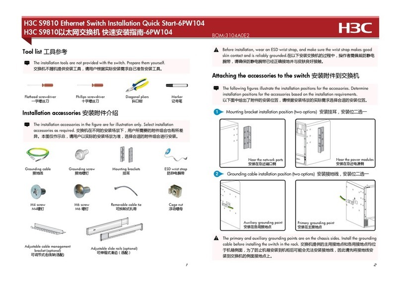
H3C S9810 Hardware Installation Quick Guide
TP-Link
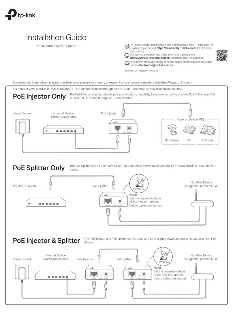
TP-Link TL-POE150S installation guide
