GDZX ZXTX-2025 User manual

ZXTX-2025
Multifunction Process Calibrator
Users Manual
Wuhan GDZX Power Equipment Co., Ltd.

1
Contents
1 Basic Introduction................................................................................. 1
1.1 Function............................................................................................................... 1
1.2 Summary of Source and Measure Functions....................................................... 1
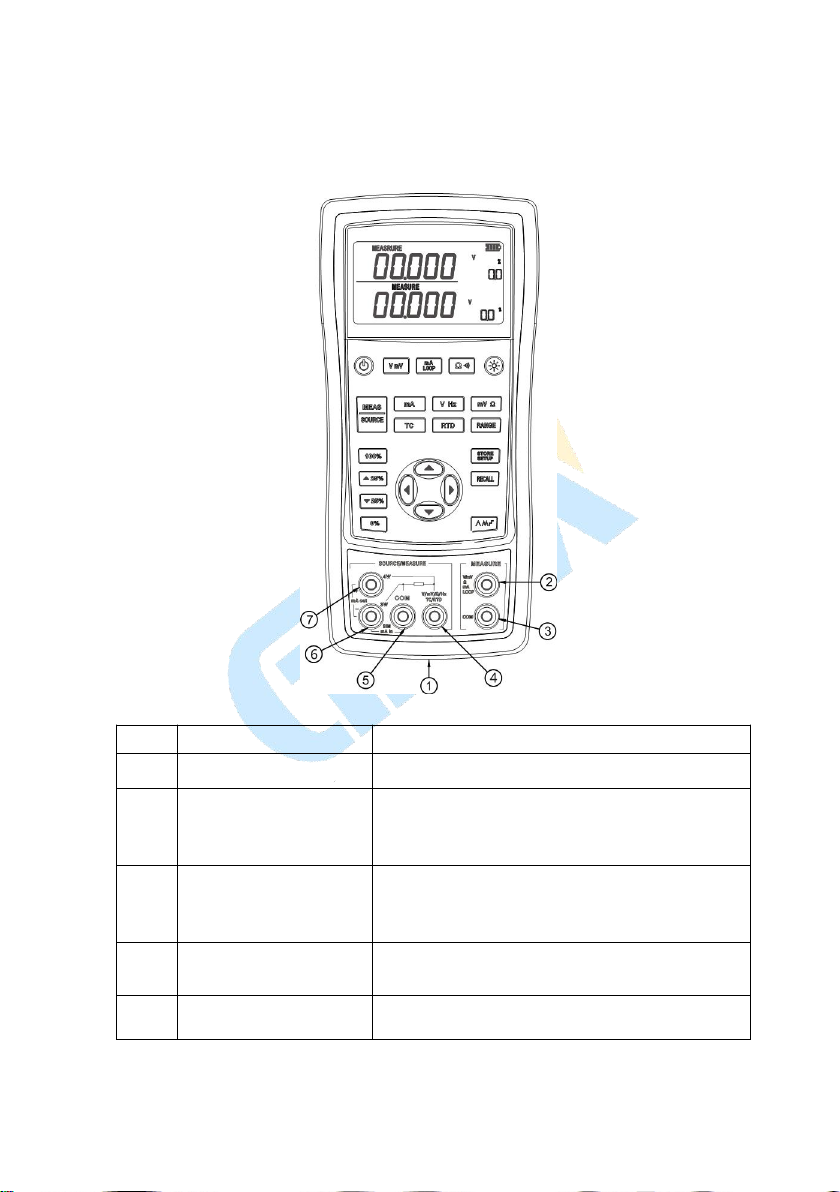
1.3 Terminal Description............................................................................................2
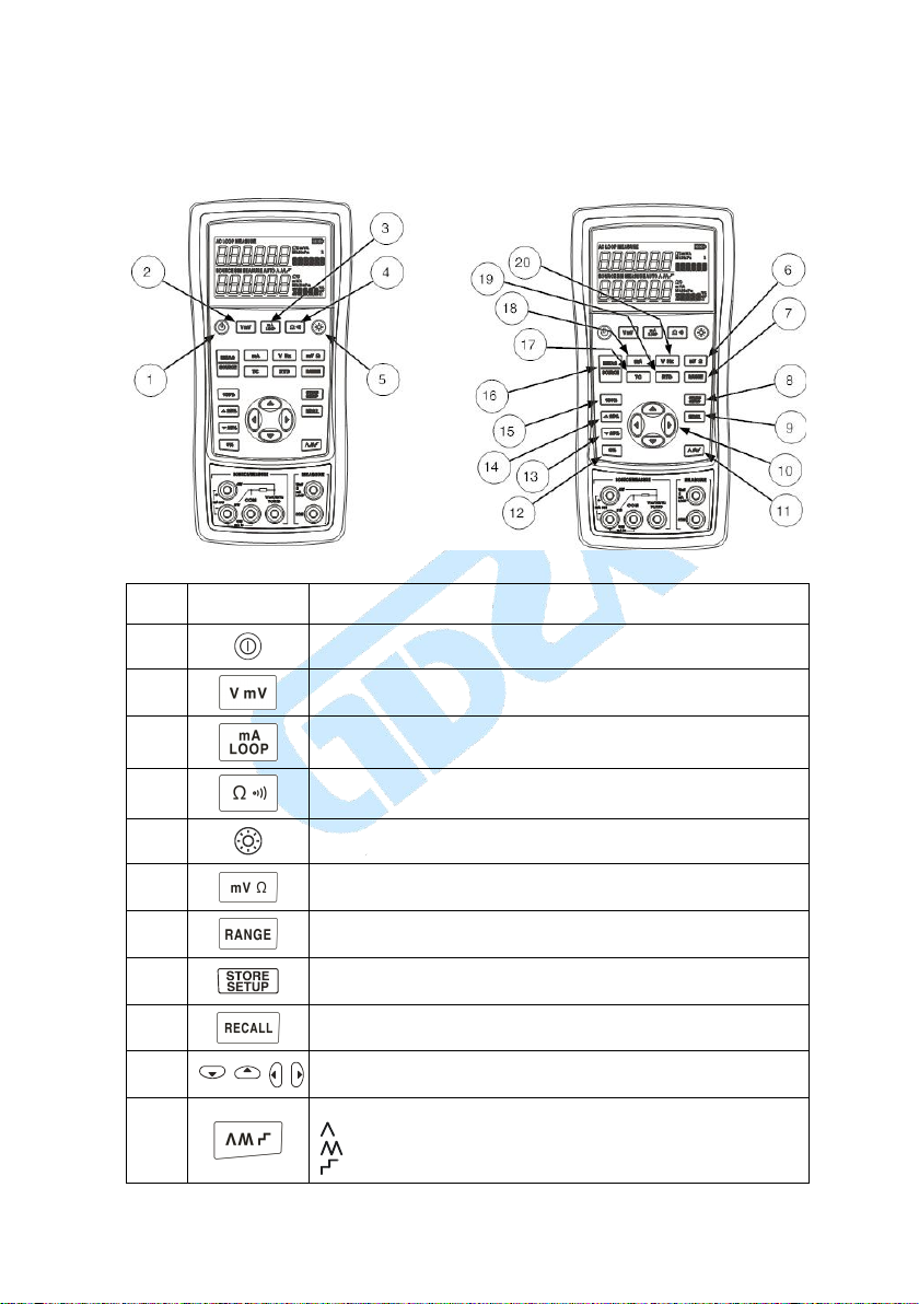
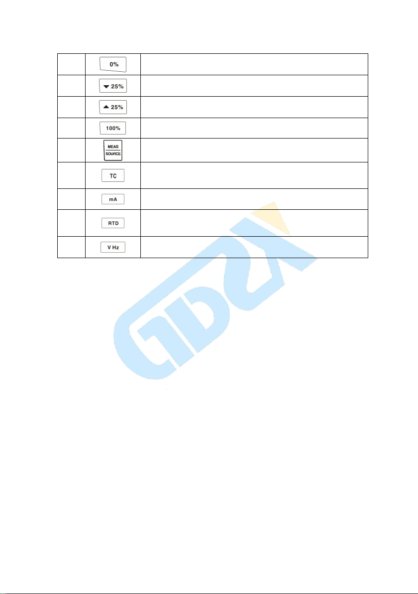
1.4 Keys description...................................................................................................3
2 Basic Operation.....................................................................................5
2.1 Measure and Source............................................................................................. 5
2.2 Shut Down Mode................................................................................................. 7
2.3 Backlight brightness Adjustment......................................................................... 7
3 Functions of Upper Display.................................................................. 9
3.1 DC V and DC mV Measurement......................................................................... 9
3.2 DC mA Measurement...........................................................................................9
3.3 Current Measurement with Loop Power..............................................................9
3.4 Resistance measure and continuity test..............................................................10
4 Functions of Lower Display................................................................11
4.1 Measure and Source of DC V and DC mV........................................................ 11
4. 2 DC mA Measurement........................................................................................11
4.3 DC mA Source(active)..................................................................................12
4.4 Simulating a 4- to 20-mA Transmitter............................................................... 13
4.5 Measure and Source of Resistane...................................................................... 14
4.6 Measure and Source of Frequency.....................................................................15
5 Temperature Measurement..................................................................17
5.1 Using Thermocouples (TC)................................................................................17
5.2 Using Resistance Thermometer Detector (RTD)............................................... 20
6 Simulation of temperature sensor........................................................22
6.1 Simulating Thermocouples................................................................................ 22
6.2 Simulating RTD................................................................................................. 22

2
7 Advanced Application.........................................................................24
7.1 Setting 0 % and 100 % Output Parameters........................................................ 24
7.2 Auto Ramping the Output.................................................................................. 25
7.3 Factory Reset......................................................................................................25
7.4 Calibrating a Transmitter................................................................................... 25
8 Power...................................................................................................27
8.1 Charge................................................................................................................ 27
9 Specifications...................................................................................... 28
9.1 DC Voltage Measurement.......................................................................... 28
9.2 DC Voltage Source.....................................................................................28
9.3 DC mA measurement................................................................................. 29
9.4 DC mA source............................................................................................29
9.5 Resistance Measurement (upper display).................................................. 29
9.6 Resistance measurement (lower display)...................................................30
9.7 Resistance source....................................................................................... 30
9.8 Frequency measurement............................................................................ 31
9.9 Frequency source....................................................................................... 31
9.10 Temperature, thermocouples.................................................................... 31
9.11 Temperature, RTD.................................................................................... 32
10 Product Accessories.......................................................................... 33
10.1 Standard Accessories........................................................................................33
10.2 Optional Accessories........................................................................................33
11 Warning.............................................................................................34

1 Basic Introduction
1.1 Function
A split-screen display. The upper display allows you to measure volts, current
(with loop power), resistance and continuity test. The lower display allows you to
measure and source volts, current, resistance temperature detectors (RTD),
thermocouples (TC), frequency, and ohms.
Calibrates a transmitter using the split-screen.
The measure of thermocouple provides automatic reference junction
Automatic and manual cold end temperature compensation for TC.
Manual stepping and automatic stepping and ramping.
Super-strong protection :The waterproof grade is IP67. Automatic protection
against the signal terminals connect to the 220V.
Support for PC communication
1.2 Summary of Source and Measure
Functions
Function
Measure
Source
DC V
0~50V (the upper display ± 30V)
0~10V
DC mA
0~24mA (the upper display ± 24mA)
0~24mA
Frequency
1.000Hz ~100.00kHz
0.00Hz~20.000kHz
Resistance
0~3200Ω
0~3200Ω
DC mV
0~100mV (the upper display ± 200mV)
0~100mV
RTD
Pt100, Pt1000, Cu50, Cu100
TC
E, J, K, T, B, R, S, N
Others
Loop supply, Step, Ramp, Dual display

1.3 Terminal Description
Figure 1.3-1
No.
Name
Description
①
Communication and
Charging connector
Connect the power adaptor to charge batteries or connect
the calibrator to the computer.
② ③
Measure V, mV, mA, Loop,
Ω and continuity test
terminals
Input terminals for measuring voltage, current, resistance,
and supplying loop power.The two terminals electrical
isolate from the other terminals.
④ ⑤
Measure and Source V, mV,
Hz, Ω, TC and RTD
terminals
Terminals for sourcing or measuring voltage, resistance,
frequency, RTD and TC.
⑤is the common Terminal.
⑤ ⑥
Measure and Source mA ,
and 3W for Ω terminals
Terminals for sourcing or measuring current ,and the
terminal ⑥is also used for the measure of 3W resistance.
⑥ ⑦
Source mA and Measure 4W
Ω terminals
Terminals for sourcing current, or for measuring resistance
of 4W.

1.4 Keys description
Figure 1-3
No.
Key
Description
1
Turns the power on or off
2
Selects DC V or DC mV measurement function in the upper display
3
Selects DC mA or Loop Power measurement function in the upper
display
4
Selects resistance measurement or continuity test function in the upper
display
5
Turns backlight on or off. Turns Contrast Adjust mode on when
powering up.
6
Selects DC mV or resistance measurement function in the lower display
7
Selects the range of source function in the lower display
8
Saves the calibrator setup. Saves Contrast Adjust setup
9
Retrieves a previous calibrator setup from a memory location
10
Increases or decreases the source level
11
Cycles through:
Slow repeating 0 % - 100 % - 0 % ramp
Fast repeating 0 % - 100 % - 0 % ramp
Repeating 0 % - 100 % - 0 % ramp in 25 % steps

12
Set output by 0% of span. Press and hold to store the source value as the
0 % value.
13
Decrements output by 25 % of span.
14
Increments output by 25 % of span.
15
Sets output by 100% of span. Press and hold to store the source value as
the 100 % value.
16
Cycles the calibrator through MEASURE and SOURCE modes in the
lower display.
17
Selects TC (thermocouple) measurement and sourcing function in the
lower display. Repeated pushes cycle through
the thermocouple types.
18
Selects current or transducer (SIM) function.
19
Selects RTD (resistance temperature detector) measurement and
sourcing function in lower display. Repeated pushes
cycle through the RTD types.
20
Selects voltage or frequency function

2 Basic Operation
2.1 Measure and Source
This section acquaints you with some basic operations of ZXTX-2025/ ZXTX-1825.
Proceed as follows to perform a voltage-to-voltage test:
1. Connect the calibrator’s the voltage output to its voltage input as shown in Figure
2.1-1.
Figure 2.1-1
2. Press more than 2 seconds to turn on the calibrator. The screen will display
all the contents for 1 second as shown in Figure 2.1-2.
Figure 2.1-2

3. Then the type of product and automatic shutdown time will be displayed for 2
seconds as shown in Figure 2.1-3.
Figure 2.1-3
4. Then the default interface of boot will be displayed as shown in Figure 2.1-4:
Figure 2.1-4
Attention: The upper and lower default modes are both based on DC voltage during turn on.
5. Press for SOURCE mode (lower screen). The screen will display as
shown in Figure 2.1-5.
Figure 2.1-5
6. Press or to increase or decrease 1 of the number that locates at the line
(the number automatic carry but the position of the line have no change). Press
or to select a digit to change.
7. Press to select 1 V for the output value, and then press and hold
until the buzzer work to enter 1V as the 0% value.
8. Press to select 5 V for the output value, and then press and hold
until the buzzer work to enter 5V as the 100% value.
9. Press and to step between 0 and 100% in 25% step increments.

The screen will display as shown in Figure 2.1-6
Figure 2.1-6
2.2 Shut Down Mode
The calibrator comes with the Shut Down mode enabled for a time duration set to 30
minutes (displayed for about 2 seconds when the calibrator is initially turned on).
When the Shut Down mode is enabled, the calibrator will automatically shut down
after the time duration has elapsed from the time the last key was pressed. To disable
the Shut Down mode, press and simultaneously. To enable the mode, press
and simultaneously. To adjust the time duration, press and
simultaneously, the screen will display as shown in Figure 2.2-1,then press and/or
to adjust the time between 1 and 30 minutes and press to store the new
duration time (Without pressing any key for 5 seconds, the calibrator will exit
automatically).
Figure 2.2-1
2.3 Backlight brightness Adjustment
To adjust the brightness of backlight, proceed as follows:
1. Press and simultaneously until “BRIGHT” is displayed as shown in
Figure 2.3-1.

Figure 2.3-1
2. Press and to adjust the brightness of backlight.
3. Press to save brightness level, will appear and then the calibrator
will enter into the work mode (Without pressing any key for 5 seconds, the
calibrator will exit automatically).

3 Functions of Upper Display
3.1 DC V and DC mV Measurement
The default function of the upper screen is DC V measurement after turn on. Press
to select DC V or DC mV and the connection is shown in Figure 3.1-1.
Figure 3.1-1
3.2 DC mA Measurement
Press to select DC mA(unit: ),the sign should not be displayed and
connection is same to that of DC V measurement.
3.3 Current Measurement with Loop Power
The loop power function activates a 24 V supply in series with the current measuring
circuit, allowing you to test a transmitter when it is disconnected from plant wiring. To
measure current with loop power, proceed as follows:
1. Connect the calibrator to the transmitter current loop terminals as shown in
Figure 3.3-1.
2. Press until and appear simultaneously.

Figure 3.3-1
3.4 Resistance measure and continuity test
Press to select resistance measurement or continuity test function circularly with
the unit of Ω and the connection is the same as DC V measurement. In the continuity
test function, the buzzer works when the measured value less than 50Ω.

4 Functions of Lower Display
The state of the upper display remains unchanged during the operation of the lower
display.
4.1 Measure and Source of DC V and DC
mV
The lower display default function is DC V measurement after trun on. If necessary,
press or to select DC V or DC mV function and press to switch
measure and source mode. The connection is shown in Figure 4.1-1.
Figure 4.1-1
4. 2 DC mA Measurement
Press to select mode, press to select DC mA measuring function
with the unit of . The connection is shown in Figure 4.2-1.

Figure 4.2-1
4.3 DC mA Source(active)
Press to select mode. If necessary, press to select DC mA
source with the unit of and then the calibrator can implement current output. The
connection is shown in Figure 4.3-1.
Figure 4.3-1
When the output load is too heavy, sign will appear in the display as shown
in Figure 4.3-2. and, at the same time, the main value of lower display will flash,
which means that the actual output current cannot reach the set value, so you should

check connection and load accordingly.
Figure 4.3-2
4.4 Simulating a 4- to 20-mA Transmitter
Simulate is a special mode of operation in which the calibrator is connected into a loop
in place of a transmitter and supplies a known, settable test current.
Proceed as follows:
1. Connect the 24 V loop power source as shown in Figure 4.4-1.
2. If necessary, press to select mode.
3. Press until and (simulation) are displayed in the screen.
Figure 4.4-1
Loop
Power
Supply
Display device

4.5 Measure and Source of Resistane
Measure
Press to select mode. If necessary, press to select resistance
function with the unit of . The interface is shown in Figure 4.5-1:
Figure 4.5-1
Attention: Over range indicate when the connection open.
Resistance measurement supports the connection types of two-wire, three-wire and
four-wire. The calibrator can be switched to three-wire or four-wire according to actual
connecting type. The respective connecting types are shown in Figure 4.5-2:
Figure 4.5-2
Press or to select a 2-, 3-, or 4- wire connection and then the calibrator will

not detect the connecting type automatically unless you quit the mode of resistance
measurement and reenter.
Source
Press to select mode. If necessary, press to select resistance
function with the unit of . The connecting type is the same as DC V measurement.
Press to switch resistance output range.(Resistance source includes 400
range and 3200 range, as shown in Figure 4.5-3 and Figure 4.5-4 )
Figure 4.5-3 Figure 4.5-4
Attention: The Figure 4.5-3 is 400 range and the Figure 4.5-4 is 3200 range.
4.6 Measure and Source of Frequency
Measure
Press to select mode, press to select frequency, its unit is .
The connection is same to DC V measurement. The screen will display as shown in
Figure 4.6-1
Figure 4.6-1

Source
Press to select mode. If necessary, press to select frequency, its
unit is . The connection is same to DC V measurement. Press to select
source range. The screen will display as shown in Figure 4.6-2.
Figure 4.6-2
Attention: The left is of 200.00Hz range and the right is of 20.000kHz range.

5 Temperature Measurement
5.1 Using Thermocouples (TC)
The calibrator supports ten standard thermocouples, including type E, N, J, K, T, B, R, S,
L, or U. Lower table summarizes the ranges and characteristics of the supported
thermocouples.
Type
Positive Lead Material
Negative Lead Material
Specified Range(℃)
E
Chromel
Constantan
-200~950
N
Ni-Cr-Si
Ni-Si-Mg
-200~1300
J
Iron
Constantan
-200~1200
K
Chromel
Alumel
-200~1370
T
Copper
Constantan
-200~400
B
Platinum (30% rhodium)
Platinum (6% rhodium)
600~1800
R
Platinum (13% rhodium)
Platinum
-20~1750
S
Platinum (10% rhodium)
Platinum
-20~1750
L
Iron
Constantan
-200~900
U
Copper
Constantan
-200~400
To measure temperature using a thermocouple, proceedas follows:
1. Connect the thermocouple to the calibrator as shown in Figure 5.1-1:
Table of contents
Other GDZX Test Equipment manuals