Bivocom TG453 Series User manual
1/ 53
®
Industrial 5G/4G IoT Gateway
TG453 Series User Guide
Note: interfaces of hardware for different models (5G and 4G version, GNSS) will be different.

2/ 53
Copyright
Copyright © XIAMEN BIVOCOM TECHNOLOGIES CO., LTD.All rights reserved.
Trademark
BIVOCOM logo is a registered trademark of Xiamen Bivocom Technologies Co., Ltd. All
other trademarks belong to their respective vendors or manufactures.
Disclaimer
Product specifications and information in this document are subject to change without
any notice, and BIVOCOM reserves the right to improve and change this user guide at
any time. Users should take full responsibility for their application of products, and
Xiamen Bivocom Technologies Co., Ltd. disclaims all warranties and liability for the
accurateness, completeness of the information published.
Global Technical &Sales Support
Xiamen Bivocom Technologies Co., Ltd.
Addr: Unit 1402-2, No. 39, Xixi Shanwei Road, Software Park #3,
Xiamen, China
Tel.: +86 158 8026 2905
Fax: +86 592 6211727
Email: support@bivocom.com
sales@bivocom.com
www.bivocom.com

3/ 53
About This Guide
Thank you for choosing Bivocom Industrial 5G/4G LTE IoT Gateway TG453 Series.
Please thoroughly read this user guide before you configure and install the device.
This manual is compatible with below models
Model
Description
TG453-NR
Industrial 5G IoT Gateway
TG453-LF
Industrial 4G LTE IoT Gateway
Note: please contact Bivocom team to choose the version of hardware you need for your
IoT application, as different interfaces on hardware will have different part number, such
as, dual sim, with/without GPS/GNSS, etc.

4/ 53
Table of Contents
Copyright .................................................................................................................................2
Trademark...............................................................................................................................2
Disclaimer................................................................................................................................2
About This Guide....................................................................................................................3
Table of Contents....................................................................................................................4
1. Introduction.................................................................................................................................6
1.1 Overview...........................................................................................................................6
1.3 Dimensions:......................................................................................................................7
1.4 Physical Characteristics..................................................................................................7
2. Getting Started...........................................................................................................................7
2.1 Package Checklist...........................................................................................................7
2.2 Installation.........................................................................................................................8
2.2.1 Insert SIM/UIM Card............................................................................................8
2.2.2 Interfaces connection...........................................................................................9
2.2.3 Power Supply......................................................................................................12
2.2.4 Cellular Antenna .................................................................................................12
2.2.5 WIFI Antenna ......................................................................................................13
2.3 LED Indicators................................................................................................................13
3. Configuration and Management............................................................................................14
3.1 View.................................................................................................................................14
3.1.1 System.................................................................................................................14
3.1.2 Network................................................................................................................15
3.1.3 Routes..................................................................................................................16
3.1.4 System Log..........................................................................................................17
3.1.5 VPN Status..........................................................................................................17
3.2 Setup ...............................................................................................................................18
3.2.1 WAN .....................................................................................................................18
3.2.2 LAN.......................................................................................................................20
3.2.3 Wireless...............................................................................................................22
3.2.4 Online Detection.................................................................................................25
3.2.5 Diagnostics..........................................................................................................26
3.3 Secure.............................................................................................................................28
3.3.1 DMZ Host.............................................................................................................28
3.2.2 Port Forwarding..................................................................................................29
3.3.3 Traffic Rules.........................................................................................................29
3.3.4 Custom.................................................................................................................32
3.4 VPN..................................................................................................................................32
3.4.1 PPTP....................................................................................................................32
3.4.2 L2TP.....................................................................................................................35
3.4.3 IPSec....................................................................................................................37

5/ 53
3.4.3 OpenVPN.............................................................................................................39
3.5 Advanced........................................................................................................................40
3.5.1 Static Routing......................................................................................................40
3.5.2 Net Flow...............................................................................................................40
3.5.3 GPS Location(Option)........................................................................................41
3.5.4 DHCP and DNS..................................................................................................42
3.6 Data Collect....................................................................................................................42
3.6.1 Basic Setting.......................................................................................................42
3.6.2 Interface Setting..................................................................................................42
3.6.3 Modbus Rules Setting........................................................................................43
3.6.4 Server Setting.....................................................................................................44
3.7 Administrate....................................................................................................................45
3.7.1 System.................................................................................................................45
3.7.2 Password.............................................................................................................46
3.7.3 Time Setting ........................................................................................................47
3.7.4 Log Settings ........................................................................................................48
3.7.5 Backup and Restore...........................................................................................49
3.7.6 Router Upgrade..................................................................................................50
3.7.7 Remote Configured............................................................................................51
3.7.8 Manual Reboot....................................................................................................53
3.7.9 Schedule Reboot................................................................................................53
3.8 Logout..............................................................................................................................53
6/ 53
1. Introduction
1.1 Overview
The TG453 is a compact 5G NR IoT gateway designed for IoT, M2M, and eMBB
applications requiring higher speed, lower latency data transmission, and capacity of
basic edge computing. It provides OpenWRT based Linux OS embedded environment
that allows developers and engineers to program and install their own application based
on Python, C/C++ to the hardware themselves.
The TG453 gateway has 5-Gigabit ethernet ports, 1-RS232, 2-RS485 to connect to
diverse field equipment and sensors, transferring the data to the cloud server via 5G/4G
LTE cellular network. It comes with industrial protocols, such as MQTT, Modbus
RTU/TCP, JSON, TCP/UDP and VPN to provide you an efficient and secure IoT data
connectivity between field devices and cloud server. The TG453 gateway has option of
dual sim/dual module for failover/load balance, providing robust and reliable wireless and
wired connectivity for your mission-critical industrial applications, such as EV charging
station, solar power, smart pole, smart cities, smart office, smart buildings, smart traffic
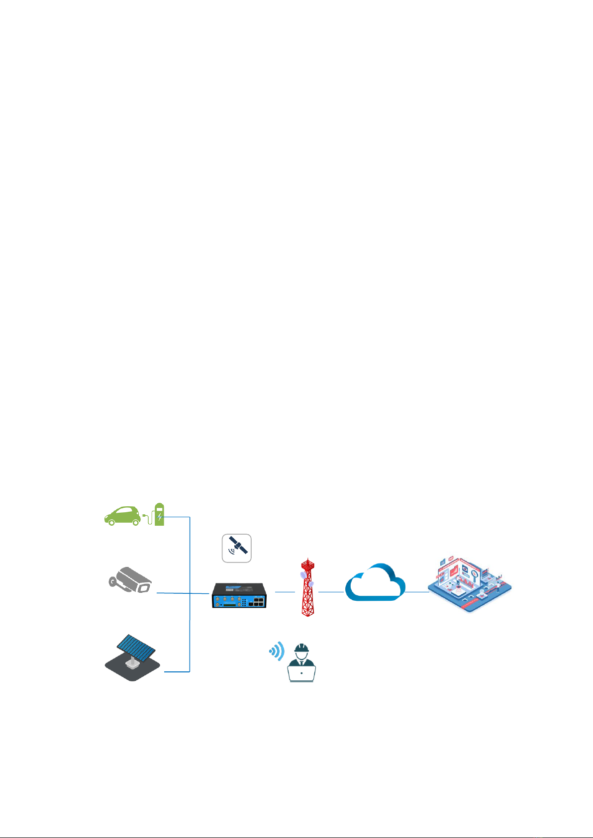
light, digital signage advertising, vending machines,ATM, etc.1.2Applications
TG453 Series IoT Gateways utilizes cellular network to connect your edge devices and
controller devices to your center for remote monitoring and control.
Typical application as below.
Image 1: Diagram of TG453 Applications
Radius WIFI
5G/4G
Data Center
IP Camera
GPS
EV Charger
Solar Panel
Internet
7/ 53
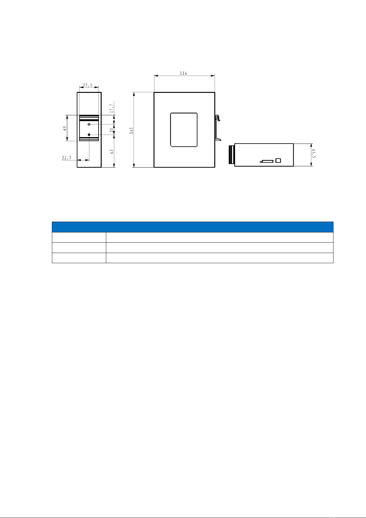
1.3 Dimensions:
i Image 2: dimensions of TG453 of different side views
1.4 Physical Characteristics
Physical Characteristics
Housing
Metal, IP30
Dimensions
145 x 114 x 45mm (5.71 x 4.49 x 1.77in), Antenna and other accessories are not included
Weight
630g(1.39lbs), without accessories
2. Getting Started
2.1 Package Checklist
The following components are included in your standard TG453 package.
Check the list before installation. If you find anything missing, please feel free to contact
Bivocom.
1. TG453 Gateway 1PCS
2. Power Adapter 1PCS
(DC 12V/1.5A, EU/US/UK/AU plug optional)
3. Cellular Antenna
5G version: 4PCS
4G version: 2PCS
4. WIFI Antenna 2PCS
5. RS232 Cable 1PCS
(DB9 Female, 1 meter)
6. Ethernet Cable(1 meter) 1PCS
8/ 53
7. 8-Pin Terminal Block 1PCS
8. 2-Pin Terminal Block 1PCS
9. DIN-Rail Mount Kits 1PCS
2.2 Installation
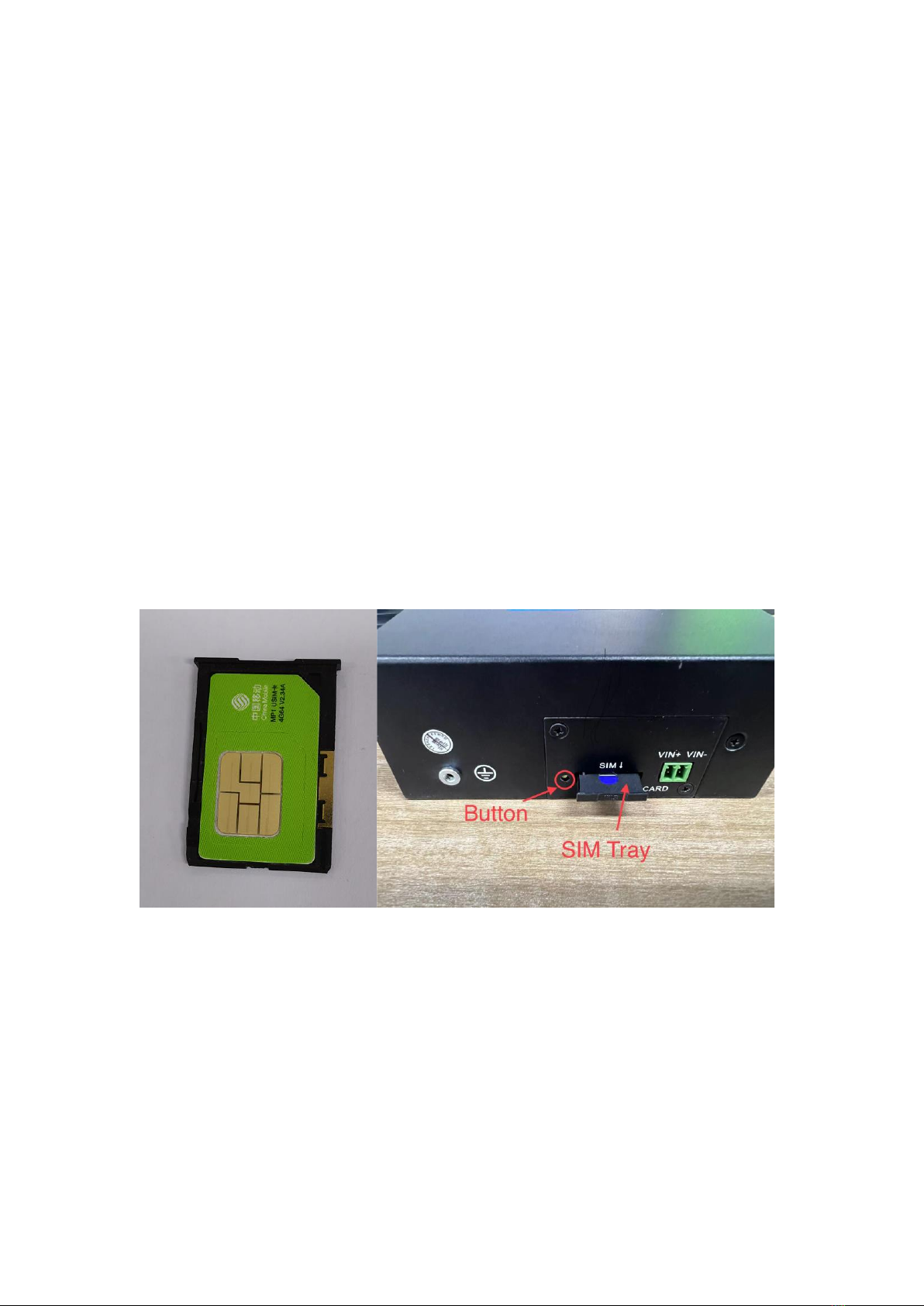
2.2.1 Insert SIM/UIM Card
TG453 supports normal SIM/UIM only, so if you’re using a Micro SIM or Nano SIM card,
you will have to use a Micro SIM or Nano SIM to Normal SIM adapter, which normally
comes with your SIM card package.
Before you insert the SIM card, make sure your router is powered off, then use a needle
object(such as a pen) to push the button near the SIM tray(see page below), it will flick
out immediately. Put the SIM card to SIM tray with chipset upside, insert it to router and
make sure it’s tightly matched.
Image 3: SIM card and SIM tray installation
Warning: DON NOT install and swap SIM/UIM card when router is powered on.

9/ 53
Image 4: Side view of TG453 with single SIM
Image 5: Side view of TG453 with dual SIM
Note: standard package only supports single SIM, dual SIM is an optional feature.
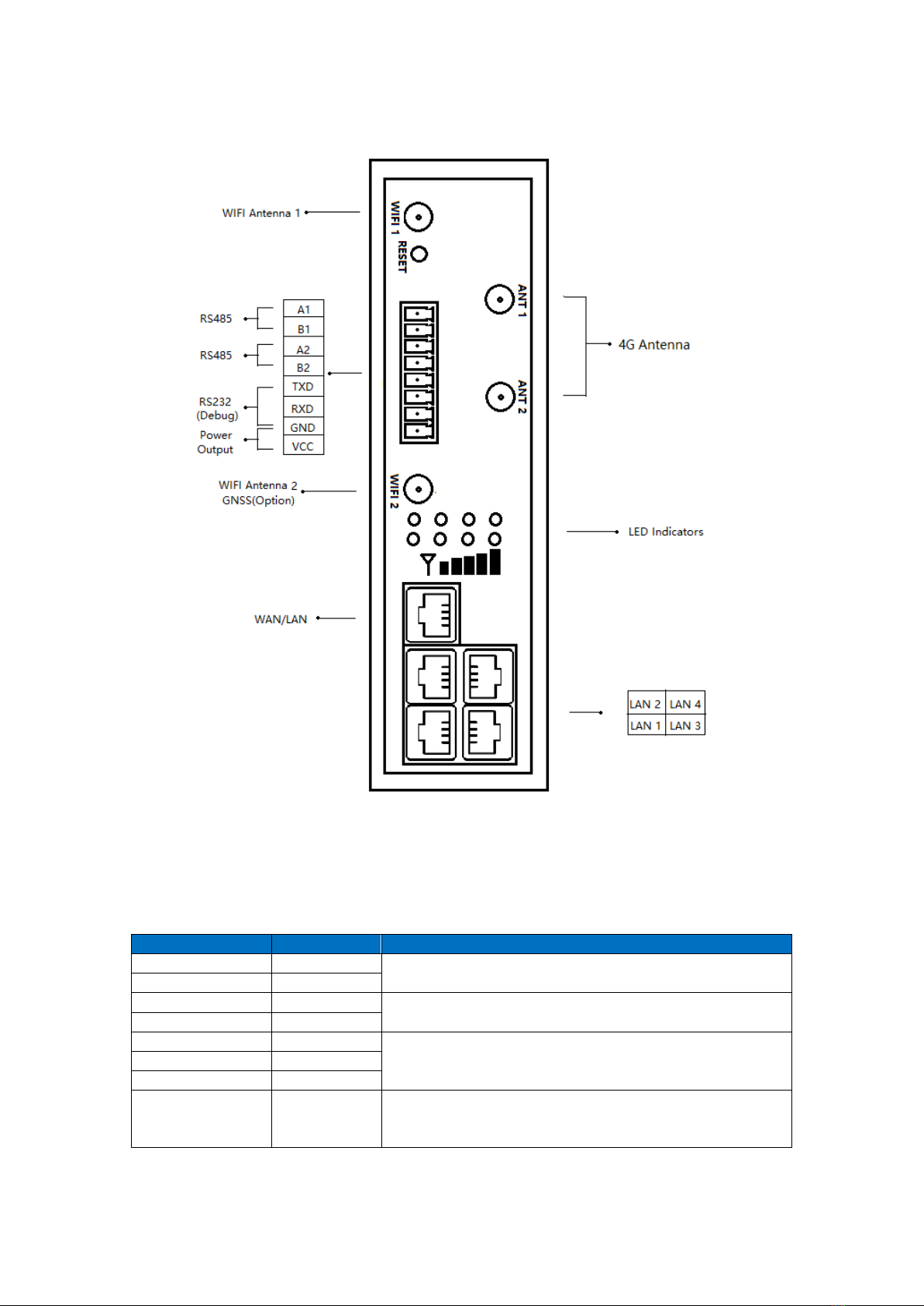
2.2.2 Interfaces connection
Hardware Interfaces Instruction (standard TG453-NR and TG453-LF as an example)
Before we start to install and configure the TG453, let’s have a quick view of the
interfaces of it.(image 6-7 and table 1)

10 / 53
Image 6: TG453-NR 5G version Interfaces
11 / 53
Image 6: TG453-LF 4G version Interfaces
1) Definition for I/O
No.
Item
Description
1
A1
RS485 port, used for connecting to sensors,
controllers
2
B1
3
A2
RS485 port, used for connecting to sensors,
controllers
4
B2
5
TXD1
RS232 port, used for debug
6
RXD1
7
GND
8
VCC1
DC power output(12VDC output, current 1A), Built-in
overcurrent protection, for external devices DC power
input
Table 1: I/O of TG453
12 / 53
TG453 support 1x RS232(Debug only) and 2x RS485 serial ports, which can be used for
IoT sensors/controllers, firmware upgrade, system log checking, debug, etc.
Besides, TG453 also comes with 1x DC power output, which is used to supply DC power
for field sensors.
TG453 designed with industrial terminal block interface, and the RS232 cable in this
package with ends of female connector and stripping cable, the signal of console cable is
defined as below.(Table 2)
RS232 Cable(with DB9 female connector and stripping cable)
Color of cable
Corresponding DB9-Female Pin No.
Corresponding Pin No. of Router
(See I/O 1)
Blue
2(RX)
3(TX)
Brown
3(TX)
4(RX)
Black
5(GND)
5(GND)
Table 2: definition of RS232 cable
RS485 Cable (not included in package)
Table 3: definition of RS485
2.2.3 Power Supply
We suggest you use Bivocom standard power adapter (1.5A/12VDC) from the standard
package mentioned-above. If you have to use your own DC power supply, make sure the
power range is 5-35VDC and it is stable enough(Ripple shall be less than 300mV, and
Instantaneous voltage shall not larger than 35V), meanwhile, power shall over 4W.
2.2.4 Cellular Antenna
TG453 provides 4 cellular antennas(TG453-NR, 5G version), which comes with SMA
male connector, screw the SMA male antenna to TG453(SMA female port, ANT 1-4,
image 6), make sure it is screwed tightly to ensure the strength of signal.
Color of cable
TG453 Router
Red
1(A)
Black
2(B)

13 / 53
2.2.5 WIFI Antenna
TG453 provides 2 WIFI antennas which comes with SMA female connector, screw the
antenna to 2 TG453 WIFI ports(male), make sure it’s screwed tightly to ensure the
strenght of signal.(image 6)
2.3 LED Indicators
TG453 Series Gateway provides 8 LED indicators, as following.
Indicator
Status
Content
Power
On
Powered On
Off
Powered Off
Signal
Strength
1 Lights
Weak signal strength
2 Lights
Middium signal strenght
3 Lights
Strong signal strenght
Online
On
Gateway accesses to Internet
Off
Gateway doesn’t access to Internet
Alarm
On
⚫SIM/UIM Card is not insert corectly or broken
⚫Antenna signal is too weak
1 Blink Per
Second
Cellular module was not registered to Gateway
2 Blinks Per
Second
Gateway can’t access to Internet
Off
Gateway doesn’t have any alarm
WIFI
On
WIFI Enabled
Off
WIFI Disabled
WAN
On
WAN is connected
Off
WAN is not connected
LAN
LAN1 Blink
LAN1 works
LAN2 Blink
LAN2 works
LAN3 Blink
LAN3 works
LAN4 Blink
LAN4 works
14 / 53
Off
LAN is not connected
Table 4: Definition of LED indicators
3. Configuration and Management
To enter into the web config UI, there are 2 ways: Via Ethernet port and WIFI
hotspot.
Use an Ethernet cable to connect the LAN port of TG453 to your laptop, or use your
laptop or mobile phone to connect to WIFI hotspot ‘Bivocom’ of TG453, login with
password of WIFI: admin123, normally your laptop will get an IP address from TG453
DHCP as 192.168.1.xx, otherwise please manually configure your laptop IP to
192.168.1.100.
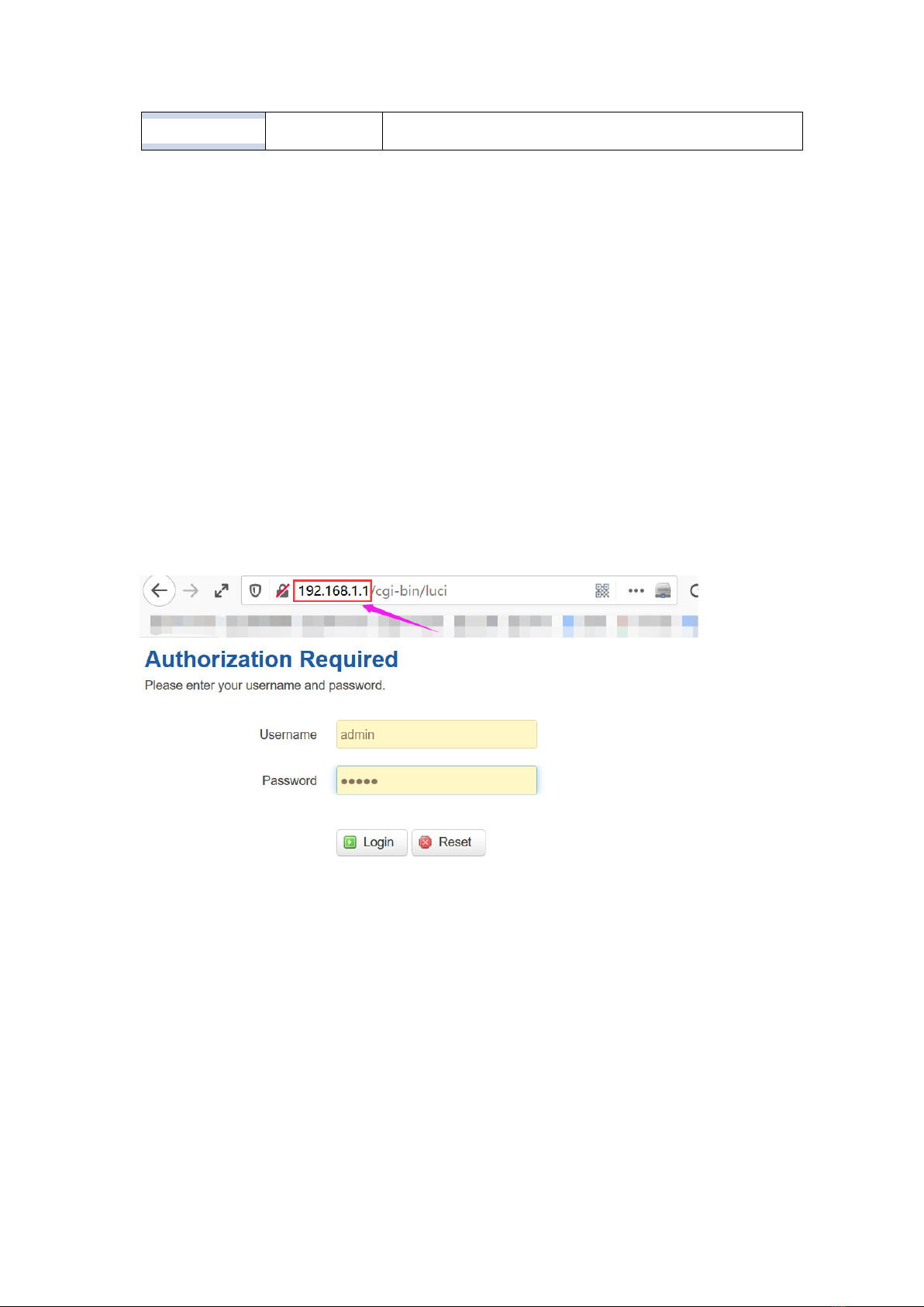
Open the browser, enter 192.168.1.1 to enter into to login page, enter username: admin,
and password: admin, to go to configuration page.
After enter into the web config page, you’ll see a list of menu on left side, as below.
3.1 View
To check the following system information.
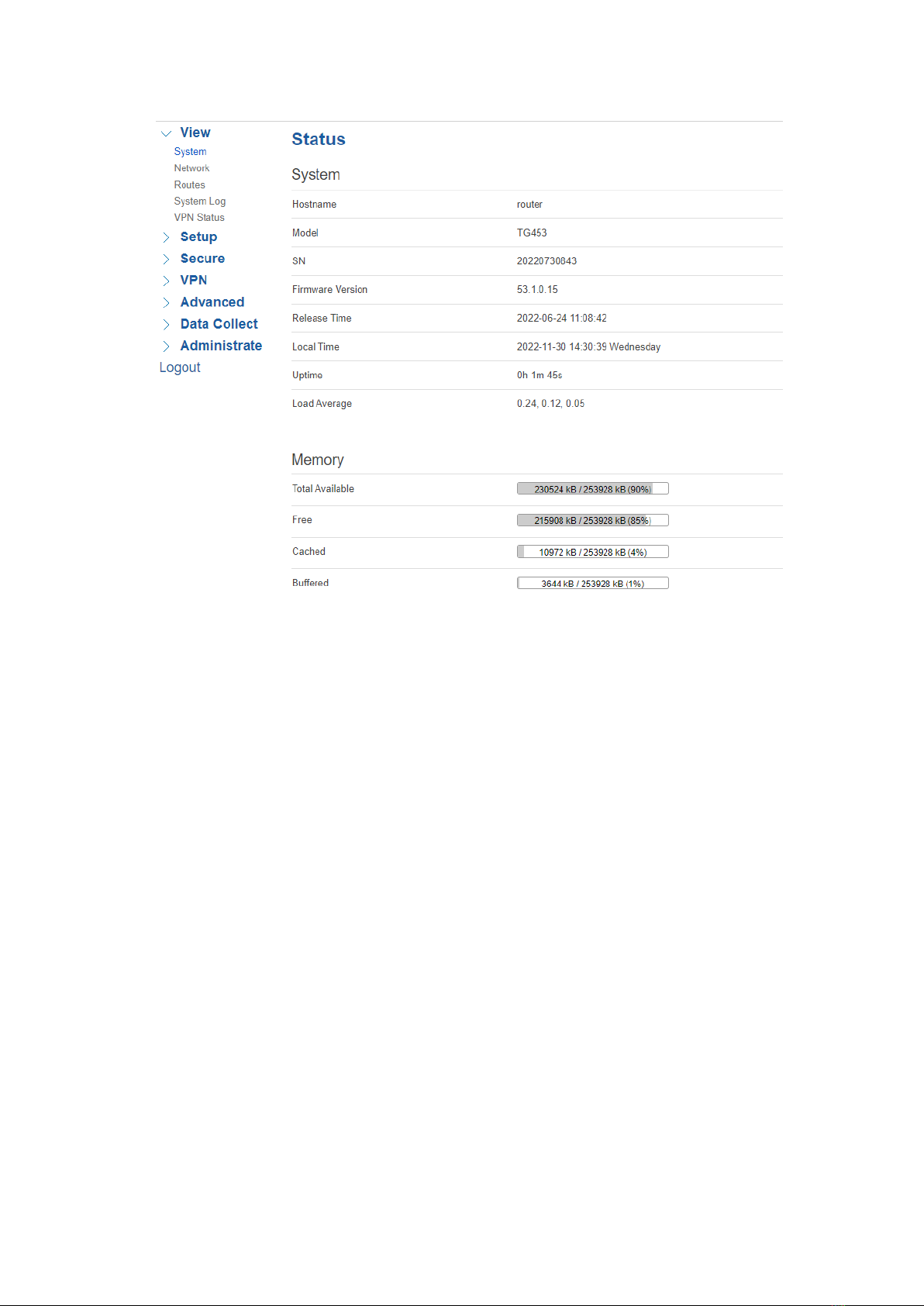
3.1.1 System
Display system related information, such as firmware version, local time, SN, uptime, etc.
15 / 53
3.1.2 Network
Display WAN, LAN, WiFi, DHCP network information.

16 / 53
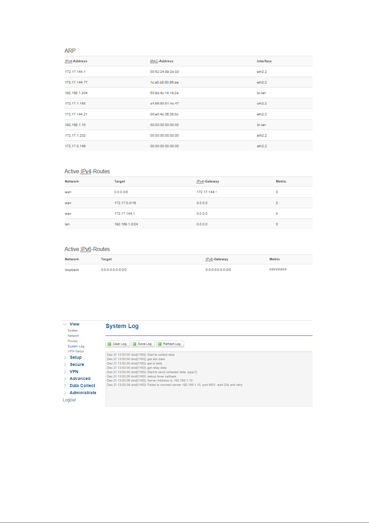
3.1.3 Routes
Display routing tables.
17 / 53
3.1.4 System Log
Display system log.
3.1.5 VPN Status
Display VPN status.
Bivocom TG453 supports IPsec, PPTP, L2TP, OpenVPN, GRE protocols, after it’s
successfully connected to your VPN server, it’ll display some info as below, such as,
Type, Connect Status, Uptime, Subnet Mask, etc.

18 / 53
3.2 Setup
Main menu of this page includes, WAN, LAN, Wireless, Online Detection, Diagnostics.
3.2.1 WAN
1) Connection Type
WAN supports DHCP/Static IP/PPPoE/3G/4G/5G connection type.
Choose the mode you need to configure the related parameters, then you can connect to
the internet.
Let’s take cellular type(5G) as an example.

19 / 53
2) Network Type
Type of network, the default value is AUTO, you can keep it as default or choose your
own preference, such as 5G only, LTE only or 3G only, etc.
3) APN
For standard SIM card, just keep it as blank, while if you’re using SIM card with APN
required, then you have to input the APN from your Telcos, and different Telcos might
have different APN, please ask your Telco if you have no idea of what yourAPN is.
4) PIN
PIN code of SIM card, normally, just keep it as blank, so please use it carefully, or the
SIM card may be locked.
5) PAP/CHAP Username
Only for private network SIM card, if you’re using public network SIM card, just keep it as
blank.
6) PAP/CHAP Password
Only for private network SIM card, if you’re using public network SIM card, just keep it as

20 / 53
blank.
7) Authentication Type
If there have username and password, you need to choose authentication type.
Normally, just keep it as default.
⚫PAP, PlaintextAuthentication
⚫CHAP, Handshake authentication
You need to choose the authentication type according to Telco’s network, or you may fail
to dial up.
8) WAN Used As LAN
When you use 5G/4G/3G/2G cellular network to access internet, you can go to
“Advanced Settings” to change the WAN to act as a LAN port.
3.2.2 LAN
Menu of LAN are mainly for configuring IP address of router, enabling DHCP server, and
assign the IP address.
The meaning of the parameters are as follows.
1) IPv4 Address
To configure IP address of LAN port, default value is 192.168.1.1, which is also the login
IP address when you want to enter into the web config page, so you can change the IP
address of LAN yourself.
This manual suits for next models
2
Table of contents
Other Bivocom Gateway manuals


 Speci?cations")


