BKI Fry Warmer FW-12 User manual
CS-TM-025.01 Revised 3/26/13
Fry Warmer
MODELS FW-12, FW-15, FW-12T, FW-15T, FW-15DTO
Servi e Manual
Serial Numbers 120182 and Higher

CS-TM-025.01 Revised 3/26/13
BKI LIMITED WARRANTY
2812 Grandview Dr. • Simpsonville, SC 29680 • USA
(864 963-3471 • Toll Free: (800 927-6887 • Fax: (864 963-5316
WHAT IS
COVERED
This warranty overs defe ts in material and workmanship under normal use, and applies
only to the original pur haser providing that:
T
he equipment has not been a identally or intentionally damaged, altered or misused;
The equipment is properly installed, adjusted, operated and maintained in a ordan e
with national and lo al odes, and in a ordan e with the installation and operating
instru tions provided with this produ t.
The serial number rating plate affixed to the equipment has not been defa ed or
removed.
WHO IS
COVERED
This
warranty
is
extended
to the original
pur haser
and applies only
to
equipment pur hased
for use in the U.S.A.
COVERAGE PERIOD
Warranty laims must be re eived in writing by BKI within one (1) year from
date of installation or within one (1) year and three (3) months from data of
shipment from the fa tory, whi hever omes first.
COB Models: One (1) Year limited parts and labor.
COM Models: Two (2) Year limited parts and labor. COM onve tion ovens also have
a two (2) year door warranty.
CO1 Models: Two (2) Year limited parts and labor. Five (5) Year limited door
warranty.
BevLes Produ ts: Two (2) Year limited parts and labor.
Warranty period begins the date of dealer invoi e to ustomer or ninety (90) days
after shipment date from BKI, whi hever omes first.
WARRANTY COVERAGE
This
warranty
overs on-site labor, parts and
reasonable
travel
time
and travel
e
xpenses
of the
authorized
servi e
representative
up
to
(100) miles
round
trip and (2)
hours
travel time and
performed
during
regular,
weekday
business
hours.
EXCEPTIONS
Any ex eptions must be pre-approved in advan e and in writing by BKI. The
extended door warranty on onve tion ovens years 3 through 5 is a parts only warranty and
does not in lude labor, travel, mileage or any other harges.
EXCLUSIONS
Negligen e
or a ts of
God,
Thermostat
alibrations
after (30) days
from
equipment
installation
date,
Air and g
as
adjustments,
Light
bulbs,
Glass doors and
door
adjustments,
Fuses,
Adjustments
to
burner
flames and
leaning
of
pilot
burners,
Tightening
of s rews
or
fasteners,
Failures
aused
by errati
voltages
or gas
suppliers,
Unauthorized
repair by
anyone
other
than
a BKI F
a tory
Authorized
Servi e Center,
Damage
in
shipment,
Alteration,
misuse or
improper
installation,
Thermostats
and safety valves with
broken
apillary tubes,
Freight
–
other
than
normal UPS harges,
Ordinary
wear and
tear,
Failure to follow
installation
and/or
operating
instru tions,
Events
beyond
ontrol
of the
ompany.
INSTALLATION
Leveling, as well as
proper
installation
and he k out of all
new
equipment
-
per
appropriate installation
and use materials – is t
he
responsibility of the
dealer
or
installer, not the
manufa turer.
REPLACEMENT PARTS
BKI
genuine
Fa tory OEM parts re eive a (90) day
materials
warranty
effe tive from the
date of
installation
by a BKI F
a tory
Authorized
Servi e
Center.

Fry Warmer Table of Contents
1
Table of Contents
Table of Contents..................................................................................................................................................... 1
Introduction .............................................................................................................................................................. 2
Safety Pre autions................................................................................................................................................. 2
Safety Signs and Messages.............................................................................................................................. 2
Safe Work Pra ti es.......................................................................................................................................... 2
Safety Labels ......................................................................................................................................................... 4
Installation ................................................................................................................................................................ 5
Instru tions For Shipping Damage ........................................................................................................................ 5
Ele tri al Information And Grounding.................................................................................................................... 5
Installation Instru tions .......................................................................................................................................... 5
FW-12 & FW-12T (Side Breather)..................................................................................................................... 5
FW-15 (Side Breather) ...................................................................................................................................... 6
FW-15 (Bottom Breather) .................................................................................................................................. 7
FW-15T/FW-15DTO (Bottom Breather) ............................................................................................................ 9
Maintenance ........................................................................................................................................................... 10
S heduled Maintenan e ...................................................................................................................................... 10
Cleaning .......................................................................................................................................................... 10
Troubleshooting ................................................................................................................................................... 11
Repair .................................................................................................................................................................. 11
Lamp Repla ement ......................................................................................................................................... 11
Replacement Parts................................................................................................................................................. 12
Components ........................................................................................................................................................ 12
FW-12/FW-15 CUF (Side Breather)................................................................................................................ 12
FW-12/FW-15 PASS THRU (Side Breather)................................................................................................... 14
FW-15 CUF (Bottom Breather) ....................................................................................................................... 16
FW-15 PASS THRU (Bottom Breather) .......................................................................................................... 18
FW-12T (Side Breather) .................................................................................................................................. 20
FW-15T (Bottom Breather).............................................................................................................................. 21
FW-15DTO (Bottom Breather) ........................................................................................................................ 22
A essories ......................................................................................................................................................... 24
Wiring Diagrams..................................................................................................................................................... 25
FW-12/FW-15 (Side Breather)............................................................................................................................. 25
FW-12/FW-15 (Bottom Breather) ........................................................................................................................ 26
FW-15 (220V England)........................................................................................................................................ 27
FW-12T/FW-15T.................................................................................................................................................. 28
FW-15DTO (Bottom Breather)............................................................................................................................. 30
Notes ....................................................................................................................................................................... 32

Fry Warmer Introduction
2
Introduction
Congratulations! You have hosen a Fry Warmer that will give you many years of fine servi e from the original
manufa turer, BKI.
The BKI name and trademark on this unit assures you of the finest in design and engineering — that it has been
built with are and dedi ation — using the best materials available. Attention to the operating instru tions
regarding proper installation, operation, and maintenan e will result in long lasting dependability to insure the
highest profitable return on your investment.
PLEASE READ THIS ENTIRE MANUAL BEFORE OPERATING THE UNIT. If you have
any questions, please onta t your BKI Distributor. If they are unable to answer your
questions, onta t the BKI Te hni al Servi e Department, toll free: 1-800-927-6887.
Outside the U.S., all 1-864-963-3471.
This unit must be sealed to the ounter after it is installed to onform to NSF Standard 4,
Item 4.28. (Dow Corning RTV #732 Multi purpose Sealant.)
Safety Precautions
Always follow re ommended safety pre autions listed in this manual. Below is the safety alert symbol. When you
see this symbol on your equipment, be alert to the potential for personal injury or property damage.
Safety Signs and Messages
The following Safety signs and messages are pla ed in this manual to provide instru tions and identify spe ifi
areas where potential hazards exist and spe ial pre autions should be taken. Know and understand the meaning
of these instru tions, signs, and messages. Damage to the equipment, death or serious injury to you or other
persons may result if these messages are not followed.
This message indi ates an imminently hazardous situation that, if not avoided, will result
in death or serious injury.
This message indi ates a potentially hazardous situation, whi h, if not avoided, ould
result in death or serious injury.
This message indi ates a potentially hazardous situation, whi h, if not avoided, may
result in minor or moderate injury. It may also be used to alert against unsafe pra ti es.
This message is used when spe ial information, instru tions or identifi ation are required
relating to pro edures, equipment, tools, apa ities and other spe ial data.
Safe Work Practices
Beware of High Voltage
This equipment uses high voltage. Serious injury an o ur if you or any untrained
or unauthorized person installs, servi es, or repairs this equipment. Always Use an
Authorized Servi e agent to Servi e Your Equipment.

Fry Warmer Introduction
3
Keep this manual with the Equipment
This manual is an important part of your equipment. Always keep it near for easy
a ess. If you need to repla e this manual, onta t:
BKI
Te hni al Servi es Department
2812 Grandview Drive
Simpsonville, S.C. 29680
Or all toll free: 1-800-927-6887
Outside the U.S., all 864-963-3471
Protect Children
Keep hildren away from this equipment. Children may not understand that this
equipment is dangerous for them and others.
NEVER allow hildren to play near or operate your equipment.
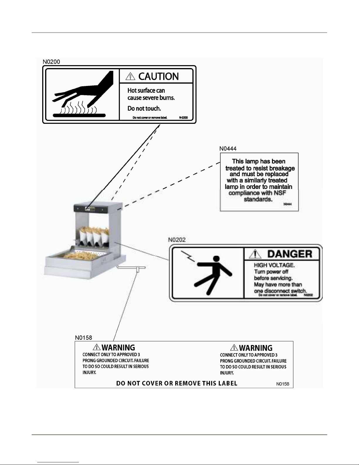
Keep Safety Labels Clean and in Good Condition
Do not remove or over any safety labels on your equipment. Keep all safety labels
lean and in good ondition. Repla e any damaged or missing safety labels. Refer
to the Safety Labels se tion for illustration and lo ation of safety labels on this unit.
If you need a new safety label, obtain the number of the spe ifi label illustrated on
page 4, then onta t:
BKI
Te hni al Servi es Department
2812 Grandview Drive
Simpsonville, S.C. 29680
Or all toll free: 1-800-927-6887
Outside the U.S., all 864-963-3471
Be Prepared for Emergencies
Be prepared for fires, injuries, or other emergen ies.
Keep a first aid kit and a fire extinguisher near the equipment. You must use a 40-
pound Type BC fire extinguisher and keep it within 25 feet of your equipment.
Keep emergen y numbers for do tors, ambulan e servi es, hospitals, and the fire
department near your telephone.
Know your responsibilities as an Employer
• Make ertain your employees know how to operate the equipment.
• Make ertain your employees are aware of the safety pre autions on the
equipment and in this manual.
• Make ertain that you have thoroughly trained your employees about operating
the equipment safely.
• Make ertain the equipment is in proper working ondition. If you make
unauthorized modifi ations to the equipment, you will redu e the fun tion and
safety of the equipment.
Fry Warmer Introduction
4
Safety Labels

Fry Warmer Installation
5
Installation
Serious injury, equipment damage or death ould result if attempting to install this unit
yourself. Ensure that an authorized BKI servi e agent install the oven.
Instructions For Shipping amage
You are responsible for filing all freight laims with the delivering tru k line. Inspe t all artons and rates for
damage when they arrive. If there is damage noted to shipping rates or artons, or, if a shortage is found, note
this on the bill of lading (all opies) before signing.
If damage is dete ted when the equipment is un rated, immediately all the delivering tru k line and follow up the
all with a written report indi ating on ealed damage to your equipment. Ask for an immediate inspe tion of your
on ealed damage item. Crating material MUST be retained to show the inspe tor from the tru k line.
Electrical Information And Grounding
Ele tro ution, equipment failure or property damage ould result if an unli ensed
ele tri ian performs the ele tri al installation. Ensure that a li ensed ele tri ian perform
the ele tri al installation in a ordan e with lo al odes, or in the absen e of lo al odes,
with the National Ele tri al Code, ANSI NFPA 70-20XX.
The FW-15DTO has 2 power supply ords. Ensure that ea h ord is onne ted to a
separate power supply ir uit. Always unplug both power ords before servi ing, moving
or testing the unit.
BKI Fry Warmers are wired for use in a ordan e with all appli able lo al, state, and federal odes. For spe ifi
ele tri al requirements and onne tions refer to the wiring diagram atta hed to the unit or provided in the Servi e
Manual.
Installation Instructions
If a side or ba k panel is removed on the hute, the other two sides must be sealed with
NSF approved sili one. Seal all inside seams greater than 1/32”.
FW-12 & FW-12T (Side Breather
Countertop Adapter (FW-12 only
1. Obtain a suitable ountertop lo ation for the unit that will provide a learan e of 4” from the side louvers.
2. Position the adapter (WN31206400) on the ountertop.
3. Using a 1/8” drill bit, drill holes in the ountertop used to se ure the adapter to the ountertop.
4. Using a 2” hole saw, drill a hole in the ountertop (dire tly under the hole in the adapter) used for the
power ord to pass through.
5. Se ure adapter to ountertop with # 8 sheet metal s rews.
6. Seal adapter to the ountertop to onform to NSF Standard 4, Item 4.28. (Dow Corning RTV #732 Multi
purpose Sealant.)
7. Feed power ord (supplied), up through holes in ountertop and adapter.

Fry Warmer Installation
6
8. Conne t wires of power ord to power entry terminal blo k a ording to the wiring diagram atta hed to
the unit or provided in the Servi e Manual.
9. Position main unit on the adapter and se ure using #8 sheet metal s rews.
10. Fit pan insert to main unit by lifting the open side of pan insert over the two tabs on main unit and lower
the pan insert into the opening in the adapter.
Countertop Cutout (FW-12 & FW-12T
1. Obtain a suitable ountertop lo ation for the unit that will provide a learan e of 4” from the side louvers.
2. Cut a 12” x 20” hole in the ountertop to fit the pan insert.
3. Using a 1/8” drill bit, drill holes in the ountertop used to se ure the main unit to the ountertop.
4. Using a 2” hole saw, drill a hole in the ountertop (under where the main unit will be se ured) for the
power ord to pass through.
5. Feed power ord (supplied), up through hole in ountertop.
6. Conne t wires of power ord to power entry terminal blo k a ording to the wiring diagram atta hed to
the unit or provided in the Servi e Manual.
7. Position main unit on the ountertop and se ure using #8 sheet metal s rews.
8. Seal main unit to the ountertop after it is installed to onform to NSF Standard 4, Item 4.28. (Dow
Corning RTV #732 Multi purpose Sealant.)
9. Fit pan insert to main unit by lifting the open side of pan insert over the two tabs on main unit and lower
the pan insert into the opening in the ountertop.
FW-15 (Side Breather
Countertop Adapter (WN31206500
1. Obtain a suitable ountertop lo ation for the unit that will provide a learan e of 4” from the side louvers.
2. Position the adapter (WN31206500) on the ountertop.
3. Using a 1/8” drill bit, drill holes in the ountertop used to se ure the adapter to the ountertop.
4. Using a 2” hole saw, drill a hole in the ountertop (dire tly under the hole in the adapter) used for the
power ord to pass through.
5. Se ure adapter to ountertop with # 8 sheet metal s rews.
6. Seal adapter to the ountertop to onform to NSF Standard 4, Item 4.28. (Dow Corning RTV #732 Multi
purpose Sealant.)
7. Feed power ord (supplied), up through holes in ountertop and adapter.
8. Conne t wires of power ord to power entry terminal blo k a ording to the wiring diagram atta hed to
the unit or provided in the Servi e Manual.
9. Position main unit on the adapter and se ure using #8 sheet metal s rews.
10. Fit pan insert to main unit by lifting the open side of pan insert over the two tabs on main unit and lower
the pan insert into the opening in the adapter.

Fry Warmer Installation
7
Countertop Cutout
1. Obtain a suitable ountertop lo ation for the unit that will provide a learan e of 4” from the side louvers.
2. Cut a 16” x 18” hole in the ountertop to fit the pan insert.
3. Using a 1/8” drill bit, drill holes in the ountertop used to se ure the main unit to the ountertop.
4. Using a 2” hole saw, drill a hole in the ountertop (under where the main unit will be se ured) for the
power ord to pass through.
5. Feed power ord (supplied), up through hole in ountertop.
6. Conne t wires of power ord to power entry terminal blo k a ording to the wiring diagram atta hed to
the unit or provided in the Servi e Manual.
7. Position main unit on the ountertop and se ure using #8 sheet metal s rews.
8. Seal main unit to the ountertop to onform to NSF Standard 4, Item 4.28. (Dow Corning RTV #732 Multi
purpose Sealant.)
9. Fit pan insert to main unit by lifting the open side of pan insert over the two tabs on main unit and lower
the pan insert into the opening in the ountertop.
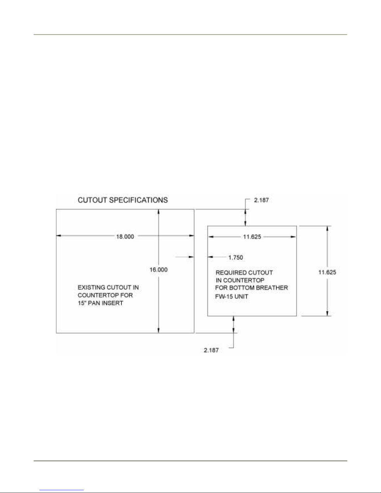
FW-15 (Bottom Breather
Countertop Collar Weldment With Liner Pan (WB31216000
1. Obtain a suitable ountertop lo ation for the unit.
2. Cut holes in the ountertop for the ountertop ollar weldment with liner pan (WB31216000) a ording to
illustration below:
3. Using a 1/8” drill bit, drill holes in the ountertop used to se ure WB31216000 to the ountertop.
Fry Warmer Installation
8
4. Se ure WB31216000 to ountertop with # 8 sheet metal s rews.
5. Seal WB31216000 to the ountertop to onform to NSF Standard 4, Item 4.28. (Dow Corning RTV #732
Multi purpose Sealant.)
6. Feed power ord (supplied), up through holes in WB31216000.
7. Conne t wires of power ord to power entry terminal blo k a ording to the wiring diagram atta hed to
the unit or provided in the Servi e Manual.
8. Position main unit on WB31216000.
9. Fit pan insert to main unit by lifting the open side of pan insert over the two tabs on main unit and lower
the pan insert into the opening in the WB31216000.
Countertop Collar Weldment Without Liner Pan (WB31211900
1. Obtain a suitable ountertop lo ation for the unit.
2. Cut a hole in the ountertop for the ountertop ollar weldment without liner pan (WB31211900)
a ording to illustration below:
3. Using a 1/8” drill bit, drill holes in the ountertop used to se ure WB31211900 to the ountertop.
4. Se ure WB31211900 to ountertop with # 8 sheet metal s rews.
5. Seal WB31211900 to the ountertop to onform to NSF Standard 4, Item 4.28. (Dow Corning RTV #732
Multi purpose Sealant.)
6. Feed power ord (supplied), up through holes in WB31211900.
7. Conne t wires of power ord to power entry terminal blo k a ording to the wiring diagram atta hed to
the unit or provided in the Servi e Manual.

Fry Warmer Installation
9
8. Position main unit on WB31211900.
9. Fit pan insert to main unit by lifting the open side of pan insert over the two tabs on main unit and lower
the pan insert into the opening in the ountertop.
FW-15T/FW-15DTO (Bottom Breather
Countertop Collar Weldment With Liner Pan (WB31217700
1. Obtain a suitable ountertop lo ation for the unit.
2. Cut holes in the ountertop for the ountertop ollar weldment with liner pan (WB31217700) a ording to
illustration below:
3. Using a 1/8” drill bit, drill holes in the ountertop used to se ure WB31217700 to the ountertop.
4. Se ure WB31217700 to ountertop with # 8 sheet metal s rews.
5. Seal WB31217700 to the ountertop to onform to NSF Standard 4, Item 4.28. (Dow Corning RTV #732
Multi purpose Sealant.)
6. Feed power ord (supplied), up through holes in WB31217700.
7. Conne t wires of power ord to power entry terminal blo k a ording to the wiring diagram atta hed to
the unit or provided in the Servi e Manual.
8. Position main unit on WB31217700.
9. Fit pan insert to main unit by lifting the open side of pan insert over the two tabs on main unit and lower
the pan insert into the opening in the WB31217700.

Fry Warmer Maintenance
10
Maintenance
Failure to omply with the maintenan e below ould result in a serious a ident.
Ele tro ution, equipment failure or property damage ould result if an unli ensed
ele tri ian performs ele tri al repair. Ensure that a li ensed ele tri ian perform ele tri al
repair.
Scheduled Maintenance
Cleaning
This unit should be leaned at the end of ea h working day. Use the following pro edure:
Failure to remove power from this unit may ause severe ele tri al sho k. This unit may
have more than one dis onne t swit h.
Never use abrasive leaners that may damage the finish.
Never steam lean the interior.
Avoid getting ex ess water in the interior of the unit.
Do not lean the heater/blower assembly by applying ompressed air.
Do not leave this unit on and unattended after business hours.
1. Turn the unit off and allow it to ool down to room temperature.
2. Remove any food.
3. Remove the pan and tray, and lean around the slotted holes at the air dis harge on the hute. Clean the
pan and tray.
4. Clean the air intakes using a mild soap and water solution. When leaning an FW-15 (Bottom Breather),
tilt unit up and lean the dust off the s reen atta hed to the base.
5. Sponge the inside and outside of the unit with a mild soap and water solution, being sure to lean all
areas. Avoid getting water in the interior of the unit.
6. Wipe the parts and unit dry with a soft, lean loth and repla e the pan and tray.

Fry Warmer Maintenance
11
Troubleshooting
Refer to the table below for troubleshooting information.
Problem Cause Possible Solution
Warmer chute is not
holding heat
Cerami heating
element failure
Conta t an authorized BKI servi e agent for
orre tive a tion.
Noisy fan Fan blade is dirty or fan
bearings are failing
Conta t an authorized BKI servi e agent for
orre tive a tion.
FW-15/FW-15T/FW-15DTO (Bottom Breather
Warmer chute is not
heating and perforated pan
is not heating
No power to unit. Make sure that the ir uit breaker and swit h at the
power supply are supplying power to the unit. If
problem persists, onta t li ensed ele tri ian.
Warmer chute is heating
and the perforated pan is
not heating
Fan has overheated and
ut off
Or
Heating oil has failed
Wipe the dust from the air intake louvers to allow
proper airflow and prevent fan overheating. Turn
the power swit h off. Wait 60 se onds. Turn the
power swit h ba k on.
Conta t an authorized BKI servi e agent for
orre tive a tion.
FW-12/FW-12T/FW-15 (Side Breather
Warmer chute is not
heating and perforated pan
is not heating
No power to unit or main
swit h is off.
Make sure that the ir uit breaker and swit h at the
power supply are supplying power to the unit. If
problem persists, onta t li ensed ele tri ian.
Warmer chute is heating
and the perforated pan is
not heating
Fan has overheated and
ut off or fan has failed
Or
Heating oil has failed
Che k to see if dust or any other obje t is blo king
the air intake. Remove blo kage if ne essary. If
problem persists onta t an authorized BKI servi e
agent for orre tive a tion.
Conta t an authorized BKI servi e agent for
orre tive a tion.
Repair
Before repla ing any parts, make sure the power has been turned off and the unit has
ooled down.
Lamp Replacement
Only use PTFE- oated lamp to prevent glass ontamination.
1. Make sure power to the unit is OFF and the unit has ooled down.
2. Carefully remove the faulty lamp.
3. Repla e with the new lamp.

Fry Warmer Replacement Parts
12
Replacement Parts
Use the information in this se tion to identify repla ement parts. To order repla ement parts, all your lo al BKI
sales and servi e representative. Before alling, please note the serial number on the rating tag affixed to the unit.
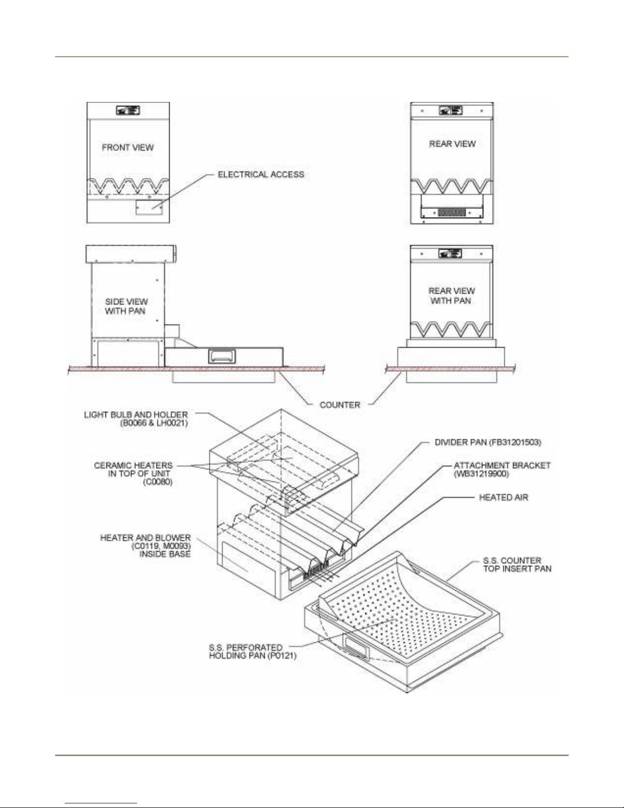
Components
FW-12/FW-15 CUF (Side Breather

Fry Warmer Replacement Parts
13
PART # QTY DESCRIPTION
B0066 1 BULB, 40A15 130V PTFE COATED
C0119 1 CALROD, 120V 1000W 140C C/U SWITCH
C0080 2 CALROD, 120V 400W CERAMIC
CS0024 1 CORD SET, 12/3 SJTO 8' 30"LEAD
FB31204803 1 DIVIDER PAN FW CUF
WB31219900
1
GREASE DEFL.RET.BRKT.WELD FW
LH0021 1 LAMPHOLDER, #62602 HI TEMP
M0093 1 MOTOR BLOWER ASSY 120V
P0129 1 PAN INSERT 12" FW
P0121 1 PAN INSERT 15" FW
S0356 1 SWITCH, ROCKER 16A 250V
Fry Warmer Replacement Parts
14
FW-12/FW-15 PASS THRU (Side Breather

Fry Warmer Replacement Parts
15
PART # QTY DESCRIPTION
B0555* 1 BULB, 150W 240V HALOGEN COATED (220V England)
B0066 1 BULB, 40A15 130V PTFE COATED
C0119 1 CALROD, 120V 1000W 140C C/U SWITCH
C0080 2 CALROD, 120V 400W CERAMIC
C0127* 1 CALROD, 220V 1000W 140C C/U SWITCH (220V England)
C0057* 2 CERAMIC HTR 400W FULL SIZE 220/240V (220V England)
CS0024 1 CORD SET, 12/3 SJTO 8' 30"LEAD
FB31201503 1 DIVIDER PAN, FW15
WB31219900
1
GREASE DEFL.RET.BRKT.WELD FW
LH0021 1 LAMPHOLDER, #62602 HI TEMP
M0093 1 MOTOR BLOWER ASSY 120V
M0091* 1 MOTOR, BLOWER ASSY (220V England)
P0129 1 PAN INSERT 12" FW
P0121 1 PAN INSERT 15" FW
S0356 1 SWITCH, ROCKER 16A 250V
* - These parts are only associated with the 220V England model

Fry Warmer Replacement Parts
16
FW-15 CUF (Bottom Breather

Fry Warmer Replacement Parts
17
PART # QTY DESCRIPTION
B0066 1 BULB, 40A15 130V PTFE COATED
C0119 1 CALROD, 120V 1000W 140C C/U SWITCH
C0080 2 CALROD, 120V 400W CERAMIC
CS0024 1 CORD SET, 12/3 SJTO 8' 30"LEAD
FB31204803 1 DIVIDER PAN FW CUF
WB31219900
1
GREASE DEFL.RET.BRKT.WELD FW
LH0021 1 LAMPHOLDER, #62602 HI TEMP
M0093 1 MOTOR BLOWER ASSY 120V
P0121 1 PAN INSERT 15" FW

Fry Warmer Replacement Parts
18
FW-15 PASS THRU (Bottom Breather
Other manuals for Fry Warmer FW-12
2
This manual suits for next models
4
Table of contents
Other BKI Food Warmer manuals

BKI
BKI Hot Food Deli Cases WDC User manual

BKI
BKI Universal Warmer UW-17 Specification sheet

BKI
BKI Sandwich/Fry Warmer FW-15L User manual

BKI
BKI WS-13 Series User manual

BKI
BKI Fry Warmer FW-12 User manual

BKI
BKI Fry Warmer HFW User manual

BKI
BKI SM Series User manual

BKI
BKI Sandwich/Fry Warmer SFW-72 User manual

BKI
BKI Extra Deep Proofing Cabinet Universal Pan Sizes... User manual

BKI
BKI Fry Warmer FW-12 User manual


