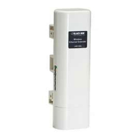
Black Box IC443A User manual
Other Black Box Extender manuals
Black Box
Black Box ACI-2000A User manual
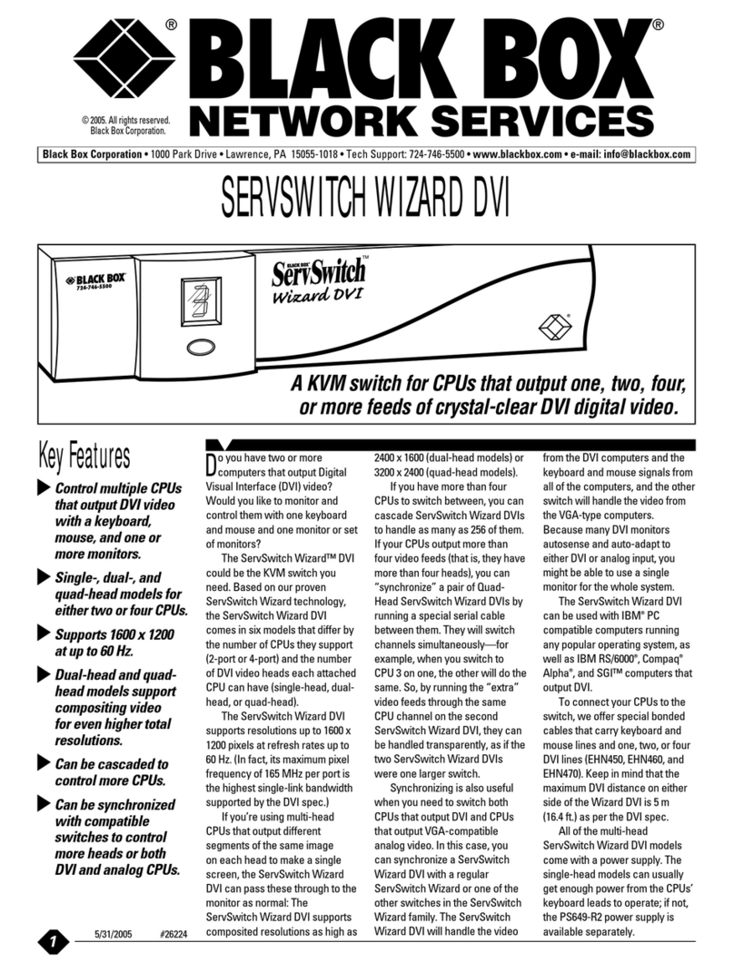
Black Box
Black Box KV1002A-R2 User manual

Black Box
Black Box VX-HDB2-KIT User manual
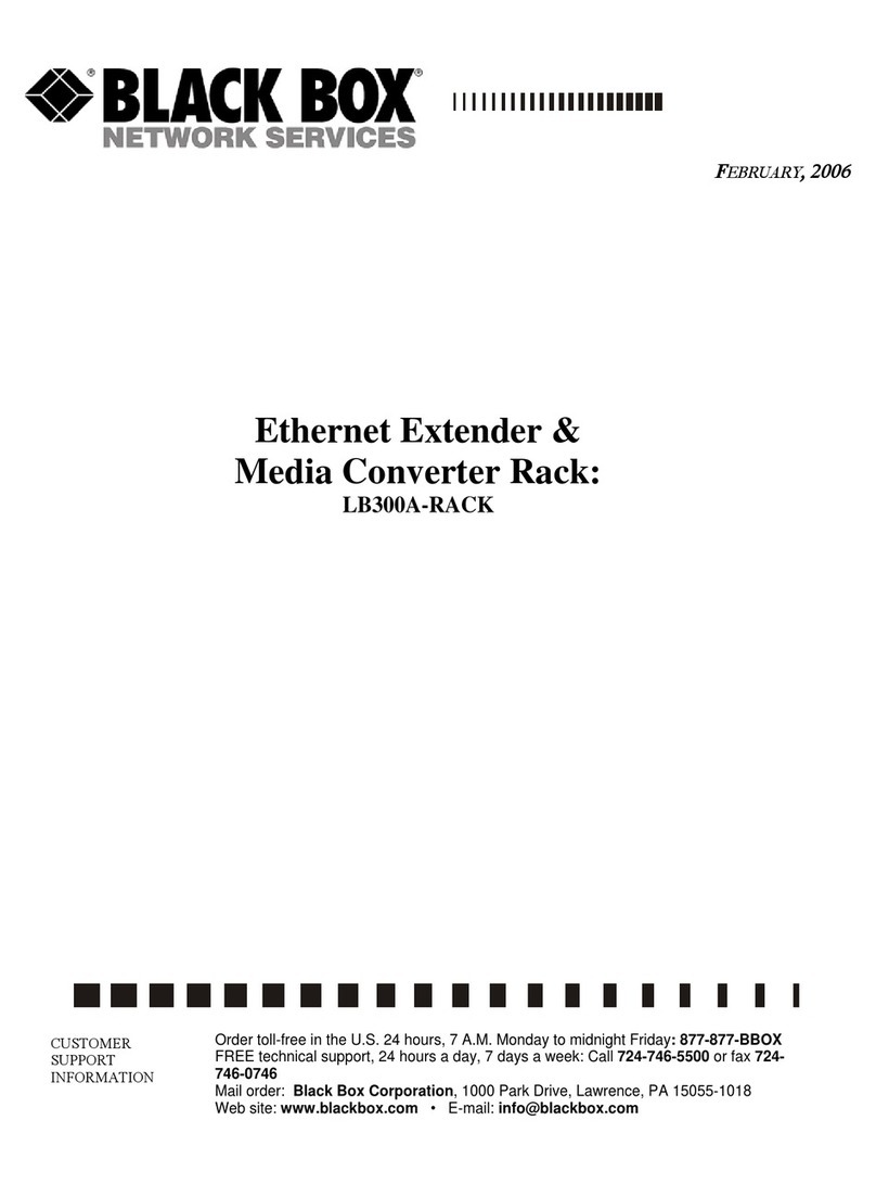
Black Box
Black Box LB300A-RACK User manual
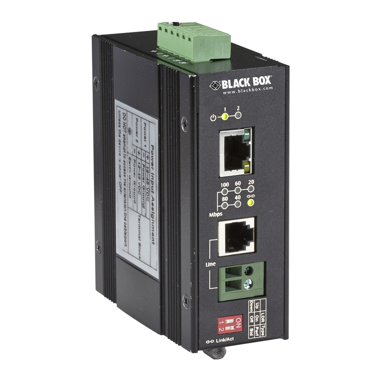
Black Box
Black Box LB323A User manual
Black Box
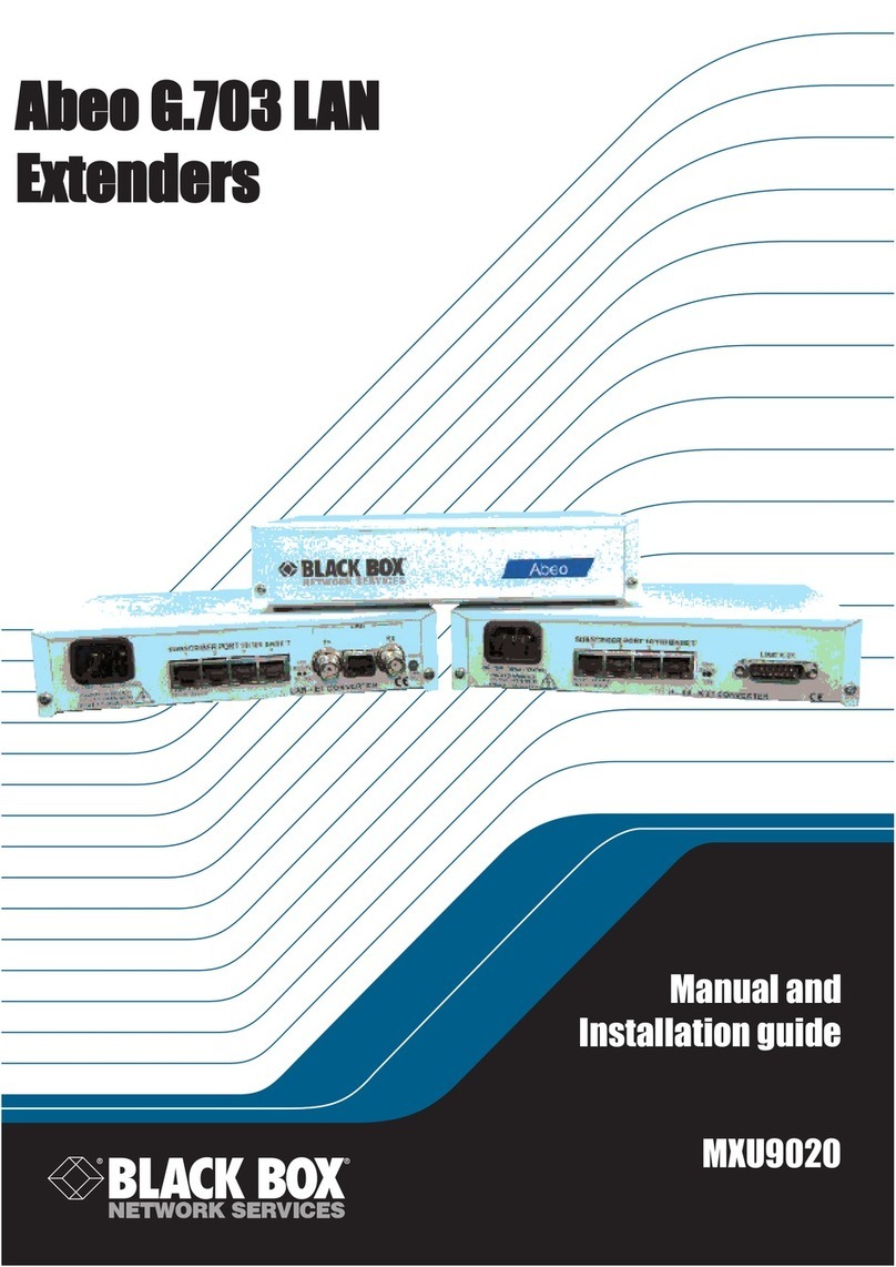
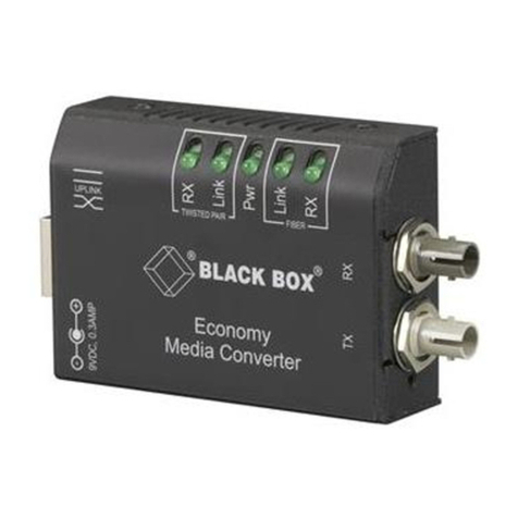
Black Box Abeo G.703 LAN Installation and operating instructions
Black Box
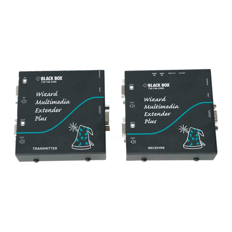
Black Box ACS1009A series User manual
Black Box
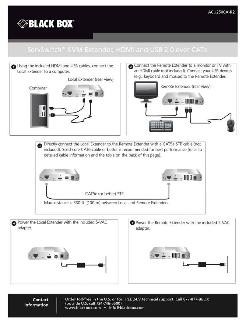
Black Box Wizard MultiMedia Plus User manual
Black Box
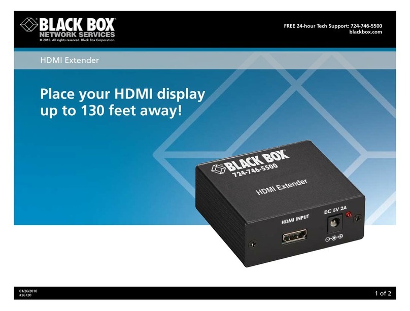
Black Box ACU2500A-R2 User manual
Black Box
Black Box AC550A User manual
Black Box
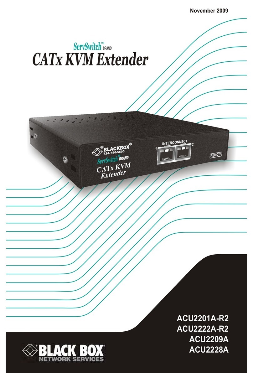
Black Box ServSwitch ACU2 01A-R2 User manual
Black Box
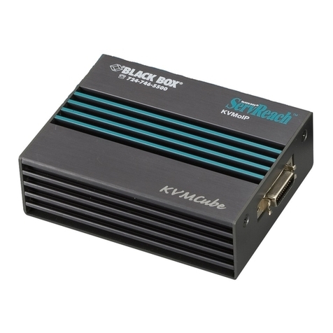
Black Box ServReach KVMCube User manual

Black Box
Black Box MEG201AE User manual
Black Box
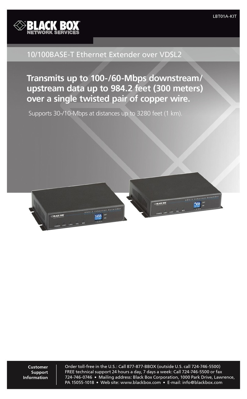
Black Box LBT01A-KIT User manual

Black Box
Black Box ServSwitch ACUDLY User manual
Black Box
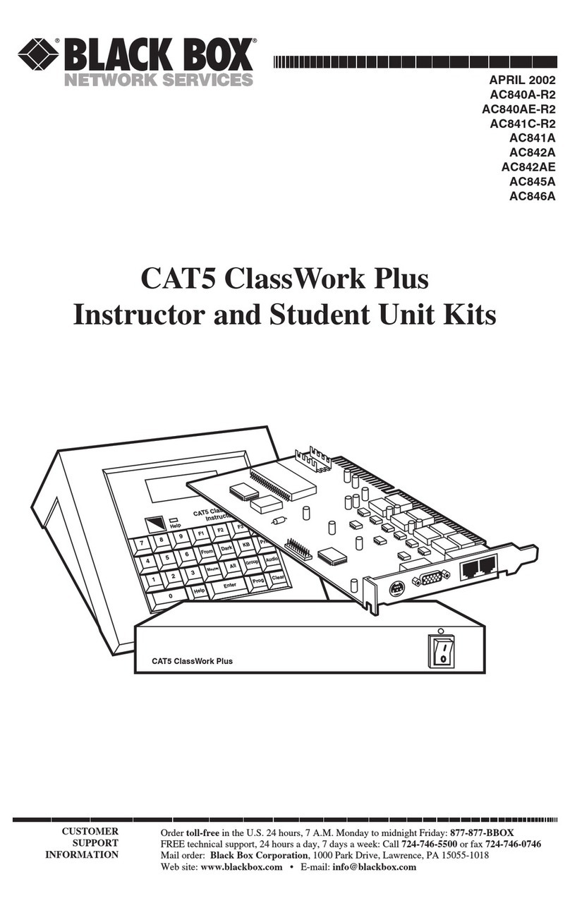
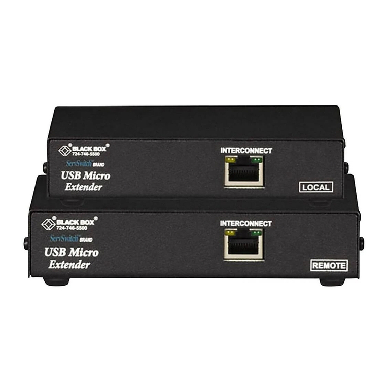
Black Box CAT5 ClassWork Plus Multiloop User manual
Black Box
Black Box ServSwitch ACU4001A User manual
Black Box
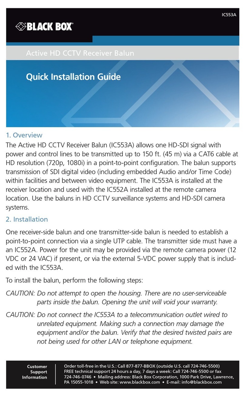
Black Box IC553A User manual

Black Box
Black Box LBLP01A-KIT User manual

Black Box
Black Box ServSwitch ACU1001A User manual
Popular Extender manuals by other brands

foxunhd
foxunhd SX-AEX01 operating instructions

TERK Technologies
TERK Technologies LFIRX2 owner's manual

Devolo
Devolo Audio Extender supplementary guide

Edimax
Edimax EW-7438RPn V2 instructions

Shinybow USA
Shinybow USA SB-6335T5 instruction manual

SECO-LARM
SECO-LARM ENFORCER EVT-PB1-V1TGQ installation manual

