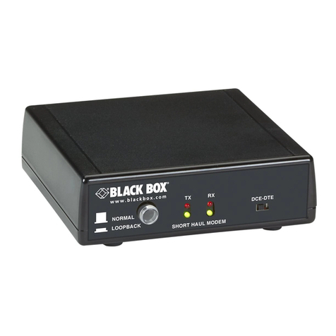
G.703 NTU W/V35
5
CONTENTS
CE Notice .................................................................................................... 2
Radio and TV Interference.......................................................................... 2
FCC Part 68................................................................................................. 3
Trademarks Used In This Manual............................................................... 3
Normas Oficiales Mexicanas (NOM) Electrical Safety Statement............. 3
1. General Information ....................................................................................7
1.1 Features ...............................................................................................7
1.2 Description ......................................................................................... 7
2. Configuration............................................................................................... 8
2.3 DIP switch configuration.................................................................... 8
2.3.1 Switch SW1-1 through SW1-8................................................ 9
2.3.2 Switch SW1-1 line coding: HDB3 (default)............................ 9
2.3.3 SW1-2 Local loop: inactive (default).................................... 10
2.3.4 SW1-6 and SW1-7 clock modes............................................ 10
2.3.5 SW1-8: Enable/disable loop tests from DTE......................... 11
3. Installation................................................................................................. 12
3.4 Connecting the twisted pair (120 Ohm) to the G.703 network ........ 12
3.5 Connecting the V.35 serial port........................................................ 12
3.5.6 Connecting to a “DTE” device.............................................. 13
3.5.7 Connecting to a “DCE” device.............................................. 13
3.6 Power connection ............................................................................. 13
3.6.8 Universal AC power (100–240VAC).................................... 13
4. Operation................................................................................................... 14
4.7 Power-up........................................................................................... 14
4.8 LED status monitors......................................................................... 14
4.9 Local loop diagnostics...................................................................... 15
4.9.9 Operating local loopback (LL) .............................................. 15
A. G.703 specifications.................................................................................. 16
B. Interface pin assignment............................................................................ 17

