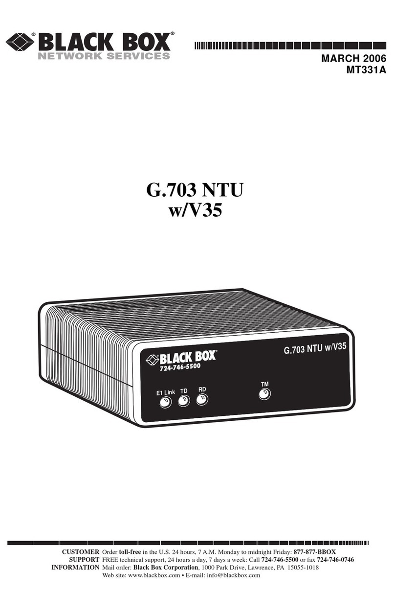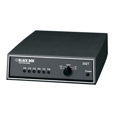
G.703/G.704 NTU W/V35
5
CONTENTS
CE Notice .................................................................................................... 2
Radio and TV Interference.......................................................................... 2
FCC Part 68................................................................................................. 3
Trademarks Used In This Manual............................................................... 3
Normas Oficiales Mexicanas (NOM) Electrical Safety Statement............. 3
1. General Information ....................................................................................7
1.1 Features ...............................................................................................7
1.2 Description ......................................................................................... 7
2. Configuration............................................................................................... 8
2.3 DIP Switch Configuration.................................................................. 8
2.3.1 Switch SW1-1 through SW1-5................................................ 9
2.3.2 SW1-6 and SW1-7 Clock Modes .......................................... 10
2.3.3 SW1-8: Enable/Disable Loop Tests from DTE..................... 11
2.3.4 Switch SW2-1 Line Coding: HDB3 (default) ....................... 11
2.3.5 Switch SW2-2: CRC-4 Multiframe....................................... 12
2.3.6 Switch SW2-3 Data Inversion............................................... 12
2.3.7 Switch SW2-4: Remote Digital Loopback Type................... 13
2.3.8 Switch SW2-5 Front Panel Switches..................................... 13
2.3.9 Switch SW2-6: V.54 Response Disabled (default)................ 13
3. Installation................................................................................................. 14
3.4 Connecting to the G.703 Network.................................................... 14
3.4.10 Opening the Case.................................................................. 14
3.4.11 Connecting the Twisted Pair (120 ohm) to the
G.703 Network ...................................................................... 15
3.5 Connecting the Serial Port................................................................ 15
3.5.12 Connecting to a “DTE” Device............................................ 15
3.5.13 Connecting to a “DCE” Device............................................ 15
3.6 Power Connection ............................................................................ 16
4. Operation................................................................................................... 17
4.7 Power-up........................................................................................... 17
4.8 LED Status Monitors........................................................................ 17
4.9 Loop (V.54 & Telco) Diagnostics.................................................... 18
4.9.14 Operating Local Loopback (LL) .......................................... 18
4.9.15 Operating Remote Digital Loopback (RL)........................... 19
4.9.16 CSU Loop............................................................................. 20

