Blankom A-PALIOS-IPM4CI 5113.81 User manual

Professional Headend Solutions
Device manual
A-PALIOS-IPM4CI
Part No: 5113.81
5113.83
8-fold IP-/ ASI-TV Modulator
IP/ SFP/ ASI (H.264/ AVC, MPEG2) →ATV (8x AM)

2
8-fold IP-/ ASI-TV Modulator
IP/ SFP/ ASI (H.264/ AVC, MPEG2) →4x CI → ATV (8x AM)
A-PALIOS-IPM4CI
Part No: 5113.81 / 5113.83
Content
1. Safety and operating instructions ........................................................................................................... 3
2. Device variants ... ....................................................................................................................................3
3. Software options .....................................................................................................................................3
4. General ................................................................................................................................................... 3
5. Main features .......................................................................................................................................... 3
6. Functional description ............................................................................................................................3
7. Explanation of the operating elements ................................................................................................... 4
7.1 Front view .......................................................................................................................................4
7.2 Meaning of the status LED‘s .......................................................................................................... 4
7.3 Rear view .... ................................................................................................................................... 4
7.4 Meaning of the LED‘s on rear......................................................................................................... 5
7.4.1 LED’s at the 10/ 100/ 1000 Mbit stream port 1........................................................................ 5
7.4.2 LED’s at the 10/ 100/ 1000 Mbit stream port 2 ....................................................................... 5
7.4.3 Status LED at the ASI socket .................................................................................................. 5
7.4.4 Status LED at the output coupler ............................................................................................ 5
7.4.5 LED‘s at the 10/ 100 Mbit control port .................................................................................... 5
8. Settings by web interface........................................................................................................................ 6
8.1 Network connection to the computer ............................................................................................. 6
8.2 Setting of individual parameters..................................................................................................... 7
8.2.1 Menu ”Overview”.....................................................................................................................8
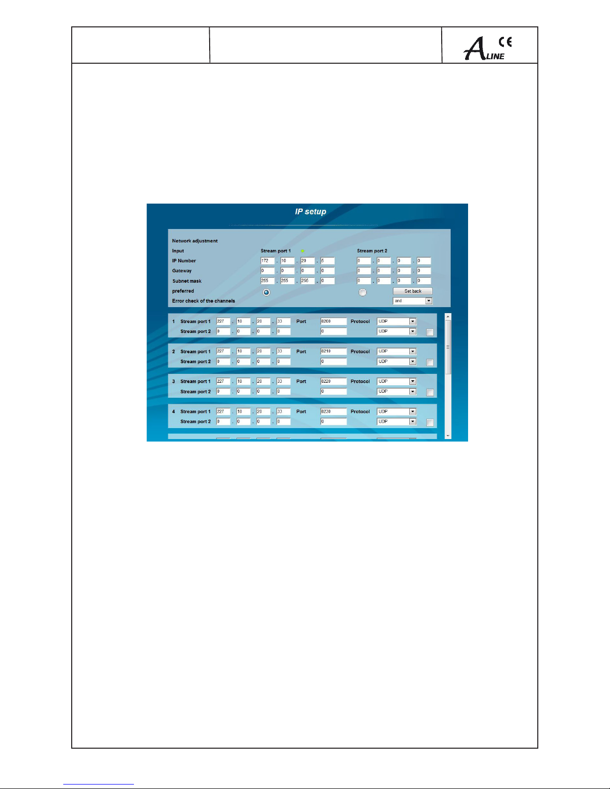
8.2.2 Menu “IP input” .......................................................................................................................9
8.2.2.1 SFP option................................................................................................................. 10
8.2.3 Menu ”CI setup” .................................................................................................................... 11
8.2.4 Menu ”Routing” ..................................................................................................................... 13
8.2.5 Menu ”Program”.................................................................................................................... 14
8.2.6 Menu ”Settings”..................................................................................................................... 14
8.2.7 Menu ”Language” ................................................................................................................. 17
8.2.8 Menu ”Setup” ........................................................................................................................ 17
8.2.9 Menu ”Service”...................................................................................................................... 22
8.2.10 Menu ”Level” ....................................................................................................................... 22
8.2.11 Menu ”Status”...................................................................................................................... 23
8.2.12Menu„Amplier“.................................................................................................................. 23
9. Factory settings ................................................................................................................................... 24
10. Block diagram ................................................................................................................................... 25
11. Application example ........................................................................................................................... 25
12. Technical data .. .................................................................................................................................. 25
13. Glossary ........... .................................................................................................................................. 26
14. Bibliography ................................................................................................................................... 27
15. Notes on the device software ............................................................................................................. 27
16. Document history................................................................................................................................ 27
Declaration of conformity................................................................................................................... 28

3
8-fold IP-/ ASI-TV Modulator
IP/ SFP/ ASI (H.264/ AVC, MPEG2) →4x CI → ATV (8x AM)
A-PALIOS-IPM4CI
Part No: 5113.81 / 5113.83
1. Safety and operating instructions
Wheninstalling,starting-upandadjustingthedevices,itisnecessarytoconsiderthesystemspecicreferencesin
the instruction manual.
The devices may only be installed and started up by authorized technical personnel.
When installing the devices into the receiving points, the adherence of the EMC regulations is to be ensured.
The installing and wiring have to be done without voltage.
With all work the defaults of the DIN EN 50083 have to be considered. It is especially important to follow DIN EN 60728-11[2].
If installed in mounting cabinets adequate air circulation must be guaranteed. The mounting in closed cabinets without
sufcientairowisnot allowed.
ThedevicesareratedprotectionclassicationI.Thereforeitisabsolutelynecessarytoinsertthemainsplugintoasocket
with protective contact.
2. Device variants
A-PALIOS-IPM4CI 5113.81 IP/SFP/ASI(H.264/AVC,MPEG2)→4xCI→ ATV (8x AM)
A-PALIOS-IPM4CI 5113.83 IP/SFP/ASI(H.264/AVC,MPEG2)→4xCI→ ATV(8xAM)incl.amplierand2xPSU
3. Software options
CKB 201 5100.51 activation test lines
CKB 202 5100.52 activation subtitles
CKB 207 5100.57 activation BISS-Function
CKB 210 5100.60 activation SFP-Port
CKB 211 5100.61 activation ASI-Port
CKB 216 5100.65 activation AC3/ Dolby Digital
CKB 227 5100.67 activation marquee
4. General
The SAT-TV Transmodulator A-PALIOS-IPM4CI is a device of the head end system A-LINE, which is conceived as a complete system
for big and middle sized networks.
The A-PALIOS-IPM4CI selects eight programs from up to eight fed-in IP transport streams or from an ASI transport stream and converts
these into analogue TV signals to transmit it in cable networks. In this case, a maximum of eight analogue television channels is
generated from the available H.264/ AVC or MPEG2 transport streams.
5. Main features
•8xIPSPTS/MPTSinput
•IPstreamingviaRJ45orSFPwithredundancy
•1xASIinput
•4xCommonInterfaceaccordingPCMCIAstandard,cascadable,multidecryptioncapable
•MPEG2/4HD/SDdecoding
•multi-standardPALmodulator
•IEdgesignalprocessing
•RFoutputswitchableassingleorwithloop
•controlofthedeviceviaHTMLorSNMP
6. Functional description
The device receives a data stream via Gigabit Ethernet. It can receive up to eight transport streams from the included IP encapsulated
transport streams. The eight transport streams are further processed in eight H.264/ AVC & MPEG2 decoders. A high-performance
FPGA does the analogue TV modulation and the freely adjustable up-conversion into the cable network range (45 ... 862 MHz). 2
Common Interface slots enables the use of 4 CA modules, which are cascadable, for the reception of scrambled signals/ programms.1
The eightfold modulator is adjacent channel compatible. A high-speed digital→analogue converter (DAC) is responsible for the excellent
outputsignal.Afteramplicationandsumleveladjustment,thecablesignaliscoupledthroughadirectionalcouplertotheoutputjacks.
1The design of the Common interface of this module is done according to DVB standards. Because of the dependencies in interaction of the DVB
signals, CA modules and smart cards we can not assure a general functional capability for all application possibilities. Please contact our servic
department for further assistance.
2Dolby - registered trademark of Dolby Laboratories, Inc.
WEEE-Reg.-Nr. DE 50389067

4
8-fold IP-/ ASI-TV Modulator
IP/ SFP/ ASI (H.264/ AVC, MPEG2) →4x CI → ATV (8x AM)
A-PALIOS-IPM4CI
Part No: 5113.81 / 5113.83
7. Explanation of the operating elements
7.1 Front view
7.2 Meaning of the status LED‘s
Designation Color Status Meaning of display
POWER green permanently on device is on
amber permanently on device is in standby
off device is off, operating voltage is not applied
SYSTEM green permanently on device is ready
ashing software update is running
amber permanently on temperature is high, fan is activated
ashing temperature is critical, the device will no longer work or is forced to shut down
off device is not ready
CH 1 ... CH 8 green permanently on channel operates without error
amber permanently on error warnings, depending on signal:
- input and/ or output without sync
- input sync, but in bad quality (eg. mosaic effect in the TV picture)
ashing hardware is faulty
off channel is off
7.3 Rear view
Status LED “SYSTEM“
Status LED “POWER“
Status LED‘s channel 1, 3, 5, 7
Status LED‘s channel 2, 4, 6, 8
2 only available in device variant 5113.83
1only available in device variant 5113.83
Ground
terminal
Stream port 2
(SFP)
Output coupler
„Input“ „Output“
ASI LED
„Status“
Control-Port
incl. LED‘s
Stream port 1
(RJ45)+LED‘s
POWER
(Redundancy)
ASI input Reset buttonStatus LED
„LOOP“ at the
output coupler
Stream port 2
LED‘s
„Link/Trafc“+„1G“
RF output
amplier2
RF input
amplier2
Fan
CIslot1+2 CIslot3+4
Test (- 20 dB) 1CAS port (for future use)

5
8-fold IP-/ ASI-TV Modulator
IP/ SFP/ ASI (H.264/ AVC, MPEG2) →4x CI → ATV (8x AM)
A-PALIOS-IPM4CI
Part No: 5113.81 / 5113.83
7.4 Meaning of the LED‘s on rear
7.4.1 LED’s at the 10/ 100/ 1000 Mbit stream port 1
Designation, color Status Meaning of display
GbE connect LED,
green
permanently on only illuminated when the connection is a GbE connection (does not light up at a
10/ 100 Mbit connection)
off no GbE connection
Connect/ data LED
yellow
permanently on cable connection is established
ashing data is received
off no cable connection
7.4.2 LED’s at the 10/ 100/ 1000 Mbit stream port 2
Designation Color Status Meaning of display
1G green permanently on only illuminated when the cable connection is a GbE connection (does not light
up at a 10/ 100 Mbit connection)
off no GbE connection
LINK/
TRAFFIC
amber permanently on cable connection is established
ashing data is received
off no cable connection or option is not enabled
7.4.3 Status LED at the ASI socket
Designation Color Status Meaning of display
STATUS green permanently on ASI transport stream is present
ashing no ASI transport stream
off option is not enabled
7.4.4 Status LED at the output coupler
Designation Color Status Meaning of display
LOOP green permanently on loop active, i.e. nominal level range 64 ... 82 dBµV
off no loop, i.e. nominal level range 76 ... 94 dBµV
7.4.5 LED‘s at the 10/ 100 Mbit control port
Designation, color Status Meaning of display
Connect LED, yellow permanently on network cable is connected
off no cable connection
Data LED, green ashing data is exchanged
off no data exchange

6
8-fold IP-/ ASI-TV Modulator
IP/ SFP/ ASI (H.264/ AVC, MPEG2) →4x CI → ATV (8x AM)
A-PALIOS-IPM4CI
Part No: 5113.81 / 5113.83
8. Settings by web interface
To use all functions of the device activate Java Script in your browser settings.
Settings via checkbox are applied immediatelly, but not stored in memory! So they would be lost on a possible restart of the
device. To save these settings the “send“ button must be pressed.
Please send and store your settings by pressing the „send“ button after each change.
8.1 Network connection to the computer
System requirements:
- PC/ laptop with 10/ 100 Mbit Ethernet interface
-Internetbrowser(e.g.WindowsInternetExplorer),capableJAVAscript
Setup the connection:
The A-PALIOS-IPM4CI has to be connected to PC network using an Ethernet cable. The default IP address of the device is 192.168.1.100.
In order to access the web interface of the A-PALIOS-IPM4CI from a PC, the PC has to be in the same subnet (192.168.1.XXX; subnet
mask 255.255.255.0), where XXX is not used by any other device in this subnet.
If multiple A-PALIOS-IPM4CI are connected to the same network each device must be set to its own unique IP address to avoid address
conicts.
After these settings, the IP address of the PC has to be adjusted to match the network. Now the devices can be accessed via browser
with the new IP address.
Ifactivated(Setup→GUISettings→Activateuserandkeywordcheck)theuserhastologinnow(»chapter8.2.8).
After successful registration or a connection establishment without password (default setting) the start page of the device is displayed
(»chapter8.2.1).

7
8-fold IP-/ ASI-TV Modulator
IP/ SFP/ ASI (H.264/ AVC, MPEG2) →4x CI → ATV (8x AM)
A-PALIOS-IPM4CI
Part No: 5113.81 / 5113.83
8.2 Setting of individual parameters
Hereyoucansetcertainparametersofthedeviceorperformcongurations.Thevarioussettingmenuscanbeselectedinthenavigation
tree on the left side. The setting is supported by an online help. If you mouse over a parameter explanations of this parameter are
displayedinanorangecoloredtextboxinthelowerpartofthescreen.Bysettinginthe“Setup“menu(»chapter8.2.8)canbeselected
so that the help is displayed in the status bar of your browser. If appropriate setting changes in the browser options are necessary.
By default status information for the device are displayed below the navigation tree. An option to move it on the right side instead is
available(»chapter8.2.8).
All eight channels are listed individually. A green LED symbol in front of “channel 1 ... 8“ means that input and output are synchronized
and that the channel operates without error. An orange colored symbol indicates that an error has occurred in that channel. An overview
of the status of various parameters of the channel is obtained by clicking the corresponding channel. A transparent LED symbol means
thatthechannelisnotconguredortheRFoutputisturnedoff.
If you click on the channels an overview window is displayed. The pop-up window closes after 20 seconds or by cklicking in its lower
part.
The „Power“ LED indicates the connection status between the network interface and the device. The „System“ LED gives an overview
over the status of system parameters of the device.
In all menus it‘s possible to switch the language between German and English on the top of the right side.

8
8-fold IP-/ ASI-TV Modulator
IP/ SFP/ ASI (H.264/ AVC, MPEG2) →4x CI → ATV (8x AM)
A-PALIOS-IPM4CI
Part No: 5113.81 / 5113.83
8.2.1 Menu ”Overview”
This page provides a status overview of the eight channels. If a channel is working without errors, “SYNC“ is displayed. If the RF power
is turned off, the display “Off“ appears behind the respective channel.
Below the staus window all devices belonging to the headend are listed (»Setup chapter 8.2.8). Functions across devices like the NIT
exchange between devices of the QAMOS group can be done on all listed devices.
The individual components of a headend are listed with their IP address. The IP address is a link, so you can switch to the next device.
Ifnoheadendwascongured,a“Search“ button is displayed. It opens the “Setup“ menu and scans the network for other A-LINE-SBL
and SBL devices. Then all available devices are listed. They can be selected and added to the headend.
By clicking the “Logout“ button the user is logged out and the login window is displayed.

9
8-fold IP-/ ASI-TV Modulator
IP/ SFP/ ASI (H.264/ AVC, MPEG2) →4x CI → ATV (8x AM)
A-PALIOS-IPM4CI
Part No: 5113.81 / 5113.83
8.2.2 Menu “IP input”
ThisisthemenuforthenetworkcongurationofthestreamingportandtheeightIPtransportstreams,fromwhichtheeightdesired
programs for transmitting can be selected.
Firstthecongurationoptionsforthetwostreamportsaredisplayed.Streamport2isonlyavailableafterenablingthesoftwareoption
(»chapter8.2.8).TheIPaddress,subnetmaskandgatewayisconguredforeachport.
ThenextstepistocongurethesetupparametersoftheeightIPinputtransportstreams(IPinputchannels).Again,IPaddress,portand
transportprotocol(UDPorRTP)havetobeenteredforeachIPchannel.Pressthe“send“ button to save the settings.
UnusedportsaredisabledbyenteringtheIPaddress0.0.0.0.
Identical settings within these 8 IP channels are not allowed and automatically marked red.
Note:
Someswitchesapplycongurationchangesforthemulticastgroupafterthesetqueryintervalhasexpired.
Some switches ignore unsolicited IGMP join message. If the querier in the switch is set to a longer interval, the switch might ignore the
emittedIGMPmessageandthusthesrtreamisnottransmittedinstantlyafterthecongurationchanged.Uponexpirationofthequery
interval, the switch checks its membership in multicast groups. The device responds. The response is accepted by the switch, which
then transmits the stream to the device.

10
8-fold IP-/ ASI-TV Modulator
IP/ SFP/ ASI (H.264/ AVC, MPEG2) →4x CI → ATV (8x AM)
A-PALIOS-IPM4CI
Part No: 5113.81 / 5113.83
8.2.2.1 SFP option
The SFP option allows the connection of different devices to the IP input. Depending on the SFP device various management and media
types can be connected to the A-PALIOS-IPM4CI. So the IP input can be expanded by another IP data source. The SFP device requires
stream port 2, with the result that either “Stream port 1“ or “Stream port 2“ can be used as an IP input.
OneofthetwoIPinputscanbedenedasthepreferredsourceandtheotherIPinputasredundancysource.IfanIPdatasourcefails,
it‘llswitchtotheotherdatasource.Individualrulescanbedened.FirstyouhavetodecidewhetheranIPinputchannelisincludedin
the monitoring. In addition, you have to choose when to switch: either when one input channel fails or when all monitored channels are
failing. The switching will occur even no signal is present on the redundancy input.
The switch back to the preferred IP input is not automatically. It has to be done manually via the user interface. Note that an
automaticswitchbasedonthedenedruleswillnotoccuruntildatawasreceivedonthemonitoredchannelsonce.
In the mask of the network settings the option of selecting the preferred IP input is displayed. The selection is done by pressing the
respective option button.
Select the line „error check of the channels“ as described above. Choose „or“ to perform the redundancy switchover if any one of the
monitored channels is failing. Choose „and“ to perform the redundancy switchover if all monitored channels fail.
The checkbox on the right side marks if the channel is included in the monitoring.

11
8-fold IP-/ ASI-TV Modulator
IP/ SFP/ ASI (H.264/ AVC, MPEG2) →4x CI → ATV (8x AM)
A-PALIOS-IPM4CI
Part No: 5113.81 / 5113.83
8.2.3 Menu ”CI setup”
Conguratethewebinterfaceofthedevicehere.TheA-PALIOS-IPM4CIhas2double-CIslotsforuptoof4CAmodules.Themodules
canbecascaded.Onetransportstreamcanberoutedthroughupto4modulesfordecryptionofservices.Firstyouhavetocongurate
the decryption, i.e. you determine which transport stream is passed through the corresponding module.
Set the transponders with the services to be decrypted on the channels 1...4. Only these can be routed through the CA modules. First
you select the pathway of transport streams of the 4 channels. There are some possibilities for routing:
First route: channel 1 →module 1, ... , channel 4 →module 4
Second route: channel 1 through device 1 and after this through module 2, channel 3 through device 3, channel 4 through
device 4, channel 2 through no device
Correspondingly are the other possibilities. For better illustration of the signal path it is displayed on the right side of the select box
graphically.
Conrmyoursettingsbypressingthe“Send“ button thereby you can continue for each module.
After these settings the multi-decryption setting can be made for each signal path. Therefor the “Multidec“ button leads to the following
menu:

12
8-fold IP-/ ASI-TV Modulator
IP/ SFP/ ASI (H.264/ AVC, MPEG2) →4x CI → ATV (8x AM)
A-PALIOS-IPM4CI
Part No: 5113.81 / 5113.83
ThismenulistsallservicesoftheadjustedtranspondersandtheirCAstatus.Ifyouwanttomakesettingsorchangesrstthe“Refresh“
button must be pressed to get the current transponder allocation. Select the services for decryption. For each of this selected services
you can determine, which streams or PID‘s have to be decrypted. That‘s important because the maximum number of the decryptable
PID‘s is limited. This limit has a different size per CA module.
In the selection boxes “MPEG 1/ 2 Audio Streams“ respective “Subtitling Streams“ you can choose if all, none or individual streams
are selectable.
If you would like to select more than one but not all, select ”all“. Then enter in the column “PID block list“ all PID‘s that shall not be
decrypted.*
The column “PID block list“ lists all PID‘s that shall not be decrypted. The PID‘s can be entered in decimal or hexadecimal format and
have to be separated by a semicolon. The maximum number of PID‘s is 10.** If “Settings all equal“ is activated, only one service for
PID selection is offered and the taken settings are automatically transferred to all other services to be decrypted.
By clicking the “Test“ button the CA module will be initialized and all services, which are saved in the CA-service-list, will be tested for
the current decryption status. Has the test ended, the result is displayed on right side. A green check mark means that the test was
successful. A red cross means that the test was not successful and the requirements for this service must be corrected, e.g. too much
PID‘s were selected.
*“Other Audio Streams“ includes all AC3-, DTS- and AAC-Streams. “Private Streams“ selects all streams which are not captured by the other selection
elds.
** Particularly PID‘s can be given here, which are active only at times and no authorisation for decryption is available for them.
Tableediting(SDT,PMT,EIT)isperformedbydefaullt.TheCAdescriptor0x09willbereplacedinthePMTthroughtheuser-dened
descriptor 0xFE. If this descriptor is already used by the service provider enable in “Setup→GUI settings→Tag selection (for decoded
pid)“ ( »section 8.2.8). Thus, the option “DVB tag (decoded TS)“ is also displayed in multidecryption menu at each service. A user-
deneddescriptorfromtherangeof0x00to0xFFwillbeselected.Itshouldbenotedthatthisdescriptorshouldnotalreadybeused
in the service.
Afterthesesettingseachofthe4CAmodulescanbecongured.Eachslotdisplaysifthemoduleisinitialized,ifitisreadyandwhich
type of module it is.
Initialize each CA moule before setting the CA services. For this purpose select the box “Reset slot“.
Set the mode of the CA PMT update in the next line. You can choose between CA PMT list or CA PMT entry. please note, that CA PMT
entry is not supported by all CAM‘s.
Some CA modules require the resource “Date & Time“ for initializing. Disable this checkbox for all ll other modules.
The CA menu shows the implemented menus. These can be selected individually or sequentially accessed in order to make settings
or to retrieve information.
By changes in the channel (e.g. transponder switching, CA module change or removal) the menu has to be passed through completely
forupdatingtheinternaltables. Forthispurpose,asdescribedabove, rst determine thechangesinthesignalpath and then call
the multidecryption menu for the affected channels. Reload the channel list again by pressing the “Refresh“ button. Then make the
appropriate stream selection. This is also necessary if a module has been removed and a free transponder has to be transmitted in this
channel. Press the “Send“ button in the „CI setup“ menu to save and send your settings.

13
8-fold IP-/ ASI-TV Modulator
IP/ SFP/ ASI (H.264/ AVC, MPEG2) →4x CI → ATV (8x AM)
A-PALIOS-IPM4CI
Part No: 5113.81 / 5113.83
8.2.4 Menu ”Routing”
In this menu you can make very clear the channel assignment of the inputs and 8 outputs. For each channel, there are two switching
options:therst(leftintheGUI)attheinputandthesecond(ontherightintheGUI)attheoutput.Thesettingisdonebyusingthe„▲“
or „▼“ button. Both on the input side as well as on the output side the assignment can be freely selected, i.e. on input side per channel
the source (IP stream 1...8, ASI TS, player) can be freely selected for further processing, on the output side, however, it can be chosen
freely, from which tuner input or media player, the transport stream including the desired TV program comes. Because this matrix of the
output channel assignment is after the CA processing, it is thus possible to distribute several decrypted channels of a transponder (if
the CA module and card support it) to various output channels.

14
8-fold IP-/ ASI-TV Modulator
IP/ SFP/ ASI (H.264/ AVC, MPEG2) →4x CI → ATV (8x AM)
A-PALIOS-IPM4CI
Part No: 5113.81 / 5113.83
8.2.5 Menu ”Program”
This is menu for the program selection of the output channels. The current channel allocation of the A-PALIOS-IPM4CI device is listed.
The following settings per channel are available:
•columnInput - Select the transponder
•columnProgram - Select the preferred program of the transponder
If the program is available in multiple languages, specify language and subtitle in the next two colums.
•columnOutput frequency - Set the channel for the selected program
Double allocation of the eight output channels is checked automatically.
Usethecheckbox“RF“ to set the RF output to “on“ or “off“.
Press the button Program search to read the list again.
8.2.6 Menu ”Settings”
Each channel can be set to your individual needs. The channels is selected by either clicking left in the navigation tree or by clicking on
the tabs above the setup tables.

15
8-fold IP-/ ASI-TV Modulator
IP/ SFP/ ASI (H.264/ AVC, MPEG2) →4x CI → ATV (8x AM)
A-PALIOS-IPM4CI
Part No: 5113.81 / 5113.83
The following parameters are adjustable:
Program list (Transponder)
If “Program selection with select box“ in Setup →GUI settings is deactivated
( »chapter 8.2.8), the screen at the left for program selection is displayed. All
programs of the selected transponder are listed with name and service ID. The
selection of the program is done by marking the respective select box. The
program name and the other parameters of the program are applied automatically.
In this case the program name in the menu “Selected program“, variant 1 is not
selectable.
Input input parameters of the channel
Input name e.g. name of the program, editable
Input selection: IP input channels 1 ... 8, ASI input
Selected program variant 1: program selection menu
Program name selection of the program from the program list of
the transponder of the selected IP TS
Service ID displays the service ID of the selected program
Load reloads the program list
Type displays the type of the program
Language selection of the available language
Direct input selection menu, manual input (see below)
Selected program variant 2: manual input
Program name displays the name of the program, which was
selected in the input menu
Load reloads the program list
Service ID service ID of the requested program,
range: 0...65535
Type selection of the program type: TV, Radio
Language language number, range: 0 ... 255
Output output parameters of the channel
Frequency input selection: channel, frequency1
Output frequency selection from channel table/ input in kHz1
Output level offset level offset2 display
RF signal selection: On, Off (Off at Time control „off“)
Sound deviation selection: 30, 50 kHz3
Sound carrier 2 adjustable in Setup menu for all channels
1If frequency input “channel“ is selected, the output frequency can be chosen from a pre-
selected channel ( » GUI settings chapter 8.2.8). If “frequency“ is selected, then the output
frequency is selectable in kHz steps.
2 Adjustment of the offset of each channel to the basic level ( » GUI settings chapter 8.2.8)
3Only selectable, if sound carrier 2 is set to “Off“. If sound carrier 2 is set to “On“, the sound
deviation is permanently 30 kHz
Video setting of the video parameters
Video output selection: On, auto Off, auto color bar
Color bar selection: On, Off
Color system adjustable in Setup menu for all channels
Video format selection: 4/3, 16/9
Scaling method selection: none, pillar or letter box, fullscreen
center (cut out)

16
8-fold IP-/ ASI-TV Modulator
IP/ SFP/ ASI (H.264/ AVC, MPEG2) →4x CI → ATV (8x AM)
A-PALIOS-IPM4CI
Part No: 5113.81 / 5113.83
Audio setting of the audio parameters
Audio gain adjustmentrange:+6...-20dB
Audio mode selection 1: mono L, mono R, dual, dual invers, stereo, auto1
selection2:monoL,monoR,monoL+R,auto2
1if sound carrier 2 is set to “On“ ( » GUI settings chapter 8.2.8)
2 if sound carrier 2 is set to “Off“ ( » GUI settings chapter 8.2.8)
VPS setting of the VPS parameters
CNI code adjustment range: 0x000…0xFFF (hexadec.)
Source PIL selection: A056(PDC), A056, PDC,
TimerControlCode
Subtitling3adjustment of the subtitle
Mode selection: Off, Teletext, DVB
Settings DVB subtitling
DVB language index adjustment range: 0...255
Use extended ID‘s selection: yes, no
Settings teletext subtitling
Teletext page adjustment range: 0..65535
Language mode selection: West, East, Russian, Arabic, Farsi
3 only available, if “Subtitling“ option is enabled ( »chapter 8.2.8)
Test lines4
The A-PALIOS-IPM4CI offers the opportunity to output test signals on up to 4 image
lines from the following selection: Off, CCIR 17, CCIR 18, CCIR 330, CCIR 331,
Sin(x)/ x, Ramp. As a default, the image lines 17, 18, 330 and 331 are selected. The
image lines selection is editable, i.e. the test lines can be output on each image line
in the range 1..625.
4 only available, if “Test line“ option is enabled ( »chapter 8.2.8)
Decryption settings5
BISS key input of the 12-digit code in BISS mode 1 or of the
16-digit code in BISS mode E
BISS-E injected ID input of the 14-digit code in BISS mode E, no
input in BISS mode 1
5only available, if “BISS“ option is enabled ( »chapter 8.2.8)
Time Control6
click the check box, to (de-)activate the functions
Switch ON select the weekday mode (Mo, Tu, ... Su);
Mo to Fr; Mo to Sa; Sa to Su and daily and start time
Switch OFF select the shutdown date and time
Marquee7
Use the checkbox (de-)activates the marquee
Position positions the text between 5 ... 100% of the
vertical position on the screen
Text color available in black or white
Background color color setting of the font background, based on the
selected font color or transparent
Text the content of the marquee
Speed set how fast the text is displayed
7only available, if “Marquee“ option is enabled ( »chapter 8.2.8)

17
8-fold IP-/ ASI-TV Modulator
IP/ SFP/ ASI (H.264/ AVC, MPEG2) →4x CI → ATV (8x AM)
A-PALIOS-IPM4CI
Part No: 5113.81 / 5113.83
8.2.7 Menu ”Language”
In this menu the user interface language can be set. You can choose between German and English. The adjustment can be made either
in the navigation tree at the point “language“ or on the top right via the language selection box.
8.2.8 Menu ”Setup”
In this menu, various administrative and system settings can be made.

18
8-fold IP-/ ASI-TV Modulator
IP/ SFP/ ASI (H.264/ AVC, MPEG2) →4x CI → ATV (8x AM)
A-PALIOS-IPM4CI
Part No: 5113.81 / 5113.83
Specically,thefollowingcanbecongured:
GUI settings
help information within the status line of the browser
By default, the online help is displayed in an orange colored text box at the bottom
of the page. If this option is selected, the help texts are displayed in the status bar
of your browser instead (must be allowed in the browser settings).
Display all system les
By default “System administration→Backup“allsystemlesareup-/downloaded
asasinglele.Byselecting„displayallsystemles“allsystemlesaredisplayed.
Nowspeciclescanbeselectedforup-/download.
Display tabs
Bydefault,thetabsareshownintheupperpartoftheuserinterface.Unselectthis
option to remove them.
Display status on the right side
By clicking the box, the status of the channels and the system is shifted to the right
of the user interface.
Optimization for low-speed data connectivity
Selecting this option reduces the image size to accodate a low-speed data
connection (GSM).
Output frequency raster
Availabe options are: B/G, D/K, M and L raster. In case of D/K1 the sound carriers
are at 6,5/ 6,25 MHz, D/K2 at 6,5/ 5,74 MHz and D/K3 at 6,5/ 6,74 MHz, the raster
forMisat6MHzandforLat8MHz.Basedonthisselectionthegroupdelaylter
is set for standard B/G, D/K, M or L raster.
Color System
You can choose between PAL, SECAM and NTSC.
Sound carrier 1 and 2 level attenuation
The setting for the audio carrier 1 is -10 ... -19 dB, for the sound carrier 2 is -17 ...
-26 dB. Sound carrier 2 can be switched on or off in the drop-down menu.
Dolby Mode
Only available if the software option „Dolby mode“ is enabled (»enabling of).
Choose beween:
Auto - automatic setting Stereo / Pro Logic Mode 1
L t/Rt - Pro Logic Mode 2
L 0/R0 - Stereo
Carrier mode
Unmodulatedsignalfortesting.
Fan mode
Available settings are Auto to ON.
Program selection with select box
If is deactivated, the program selection is done via program list in the adjustment
menu. Otherwise the program selection is done in the eld “Selected program“
(»chapter 8.2.6).
Activate user and password check
This option can only be deactivated by the administrator. If disabled, no login is
required ( »chapter 8.1).
SBL headend
Lists all A-LINE-SBL and SBL devices, which are found in the same network. By
pressing the “Search“ button the list is updated. All marked devices belong to the
headend and are displayed on the “Overview“ page.

19
8-fold IP-/ ASI-TV Modulator
IP/ SFP/ ASI (H.264/ AVC, MPEG2) →4x CI → ATV (8x AM)
A-PALIOS-IPM4CI
Part No: 5113.81 / 5113.83
System administration
Thedefaultistosaveorloadthecompleteconguration(seerstpicture).
Backup
Herethesystemlescanbeloadedorsavedasapackage(exceptlogbook.txtand
status.xml).Thus,itispossibletocopythesystemlesfromaA-PALIOS-IPM4CI
device to another. If under GUI setup→Display all system les is selected, the
systemlescanalsobeloadedorsavedseparately(seegurebelow).Additional
systemlescanbeadded.
Update
Click the „Load“-Button to load a software update.
The button “View logbook“ leads to an overview, in which all the processes have
been documented since the start of the GUI. Each operation is listed by date,
time and description. If operations have been executed, the logged on user, who
initiated the action, is saved too. By pressing of the “Erase“ button all entries are
deleted, only possible by the administrator.
System
Location
InthiseldanamefortheA-PALIOS-IPM4CIcanbeenteredtoidentifythedevice
easily. The name will appear on the top right of the website below the language
selection box. It is provided via SNMP: Iso(1)org(3).dod(6).internet(1).mgmt(2).
mib.2(1).system(1).sysLocation(6).
Logout
restarts the user interface
Default
reset to factory default
Reboot
restart of the A-PALIOS-IPM4CI device
Enabling of
Possible software options for the A-PALIOS-IPM4CI device can be enabled. The
registrationcodemustbeenteredintheinputeld and by pressing the “Send“
button. Activated options are displayed in black, inactive are grayed out.

20
8-fold IP-/ ASI-TV Modulator
IP/ SFP/ ASI (H.264/ AVC, MPEG2) →4x CI → ATV (8x AM)
A-PALIOS-IPM4CI
Part No: 5113.81 / 5113.83
Date and time
Clicking the “Set“ button, the date and time will be set to that of the PC.
Webserver
The A-PALIOS-IPM4CI supports the DHCP functionality. DHCP-Client is factory
default. Note, that after each factory reset the A-PALIOS-IPM4CI is set to “DHCP-
Client“.
If the DHCP functionality is set to “Off“,theappropriateeldsforIPnumber,
subnetmaskandgatewaycanbesetmanuallytotthenetwork.
If the device is set as “DHCP-Client“, it automatically obtains an IP address from
the DHCP server on the network. The manual network settings are disabled.
By pressing the “Info“buttontheautomaticallyassignednetworkconguration
of
the device is displayed. Close the window by clicking in its lower area or wait
20 seconds.
Please note: if the device is set as “DHCP-Server“, the IP address 192.168.1.100
must not be set. If you select this address an error message will be displayed.
InadditiontotheIPsettings,youcanconguretheDHCPrangefromwhichthe
connected client IP addresses are assigned. The address range has to match
the IP address and subnet mask of the server and should not be too small. The
default is 192.168.1.1 to 192.168.1.99.
Along with the DHCP server a local DNS (Domain Name Server) will be set up.
TouseitinfullextentaconnectedPC/laptopmustbeconguredasaDHCP
client. Note that, using Windows, not only the IP address but also the DNS
server address has to be obtained automatically.
IfthedeviceisconguredasaDHCPserverorclientandtheclienthasreceived
an IP address successfully, the device can be accessed via a web browser using
itsname.Thisnameiscomposedoftheprex“sbl“andthedevicenumberthat
is printed on the back of the device and on the packaging. For example, the
device with the number 0123456 can be found under “sbl0123456“. It might be
necessarytoaddthedomainname.Incasethatthedevicewasconguredas
a server, the name of the domain is “sbl0123456.sbl“. If another DHCP server is
used, ask your administrator for the domain name.
Anexampleforthesimplicationofthecongurationoroperationoftheheadend
viaDHCPis,thatanA-LINE-SBLdeviceisconguredasaserver,theremaining
devicesandtheconnectedPC/laptopareconguredasaclient.
By calling “dhcp.sbl“ in the browser the GUI of the server device is loaded.
Now the headend can be read. So all connected components are found and
listed. The headend can now be stored in the Setup→System administration. By
selecting the respective devices link in the headend overview, you can switch to
the other devices user interface quickly.
This manual suits for next models
1
Table of contents
Other Blankom Modulator manuals

Blankom
Blankom SAT-TV User manual

Blankom
Blankom HDC 6012 User manual

Blankom
Blankom 5105.82 User manual

Blankom
Blankom AMB 307 User manual

Blankom
Blankom AMA 299 Application guide

Blankom
Blankom A-QAMOS-4CI Application guide

Blankom
Blankom PALIOS-IPM4 5105.10 User manual

Blankom
Blankom QAMOS-CT Application guide

Blankom
Blankom HDC 7016 Instruction Manual

Blankom
Blankom HDC 6008CI User manual