4
STB 016
Part No: 9710.02
SAT-TV Transmodulator
DVB-S/ S2→DVB-C/ ITU-T J.83 Annex B, C
LINE
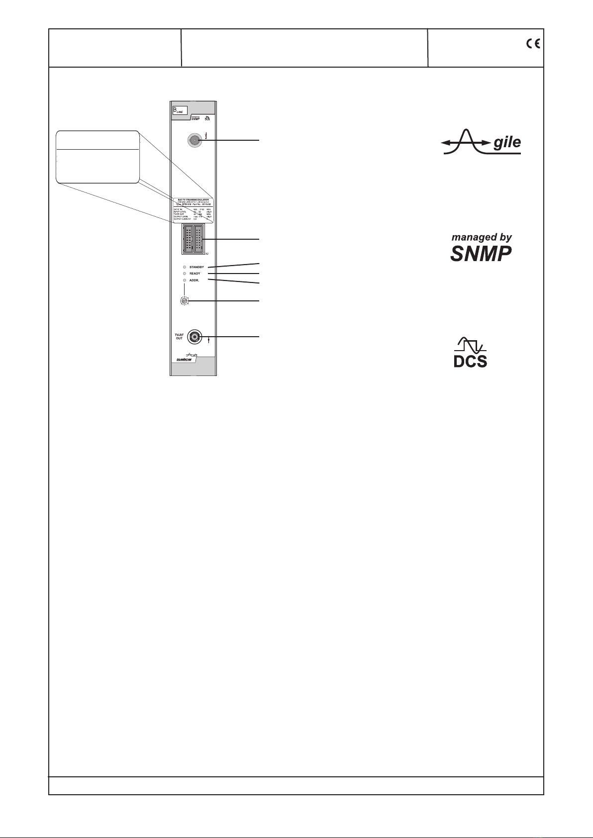
7. Meaning of status LED`s on front panel
Designation (Colour)) Status Meaning of display
STANDBY (red) permanently illuminated Module is on standby
flashing Module faulty (hardware) or level error
READY (green) permanently illuminated Module working, everything ok
flashing Dysfunction depending in signal:
Tuner not sync (e.g. in case of missing input signal)
no input on the QAM modulator
buffer overflow in the QAM modulator
QAM overflow (input data rate on the QAM modulator too large)
off RF output is deactivated
ADDR. (yellow) illuminated or flashing Remote control making contact/ data transmission
8. Programming by web server *
8.1 Main menu
Name of device, item number, module address in head end
Description module name (max. 30 characters)
Input
SAT-IF adjustment range: 950 ... 2150 MHz
Symbol rate adjustment range: 2000 ... 45000 MSps
Status display wether SYNChronization or
noSYNChronisation with input
Output
Channel channel selection accord. QAM standard:
DVB-C/ Annex A: 2 ... 69, standard B/G
Annex B, C: 2 ... 134, standard M
Dämpfung adjustment range: 0 ... 31.5 dB
QAM-Symbol rate selection: 6995, 6900, 6875, 6111, 6000,
3450, 1750 kSps
QAM-Modulation
mode selection: 16, 32, 64, 128, 256 QAM
RF-Signal selection: On/ Off
Status
Operating mode
QAM-Modulator according adjustment menu 1
QAM-Standard DVB-C (Annex A)/ ITU-T J.83B (Annex B)/
ITU-T J 83C acc. adjustment menu 1
NIT-Processing On/Off according adjustment menu 1
CAT-Processing On/Off according adjustment menu 1
Change TS-Identif. On/Off according adjustment menu 1
Program filter On/Off according adjustment menu 1
Operating status selection: On/ Off/ Reset
SNMP trap message selection: On/Off,if SNMP option in HCBx00
enabled, otherwise „locked“ display
Level monitoring On/Off
Factory settings setting the default values (see menu 7)
Routing to the appropriate adjustment menu
Extended settings see menu 1
NIT table see menu 2
Program filter see menu 3
Data rate overview see menu 4
Software overview see menu 5
Status see menu 6
* Further details on this are to be found in the HCB manual