manuals.online logo
Brands
  1. Home
  2. •
  3. Brands
  4. •
  5. Blaupunkt
  6. •
  7. Car Navigation System
  8. •
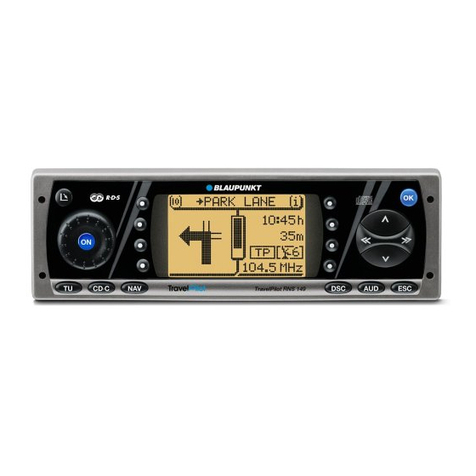
  9. Blaupunkt TravelPilot RNS 149 Service manual

Blaupunkt TravelPilot RNS 149 Service manual

NAVIGATION
Schaltbild • Circuit diagram
8 622 402 077 WG-KN 10/99
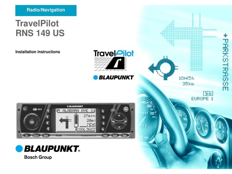
TravelPilot RNS 149
7 612 001 327
TravelPilot RNS 149 US
7 612 001 387
VORSICHT!
Das Gerät beinhaltet eine Laserkomponente!
Im Servicefall nachfolgende Hinweise
beachten:
• Das Gerät arbeitet mit unsichtbarem Laserstrahl.
Bei geöffnetem Gerät tritt im Bereich des Plattenfaches
Laserstrahlung aus.
• Nicht in den Strahl blicken.
• Unbeteiligte Personen vom Arbeitsplatz fernhalten.
• Der Betrachtungsabstand darf 13cm nicht unterschreiten.
Kann dies nicht eingehalten werden, muß eine geeignete
Laserschutzbrille getragen werden.
CAUTION!
This unit contains a laser component!
For service observe the following important
instructions:
• The unit operates with an invisible laser beam.
When the cover is removed, near the disc compartment, invisible
laser beams are apparent.
• Avoid direct eye contact with these beams.
• Keep other people away from the working place.
• The viewing distance should not be less than 13cm.
If this distance cannot be ensured, use suitable laser safety
goggles.
D GB
CLASS 1
LASER PRODUCT
UNSICHTBARE LASERSTRAHLUNG
NICHT DEM STRAHL AUSSETZEN
LASERKLASSE 3B
Block diagram ........................................................3
Circuit diagram Connector board 0529 A03.........40
Circuit diagram GPS board 8887 A04 V01 ...44 - 46
Circuit diagram Gyro board 0585 A02..................43
Circuit diagram Key board 0530 A05............47 - 48
Circuit diagram Main board 0531 A05
Connections.................................................7 - 9
MCM modul .............................................10 - 12
CO processor / TIM..................................13 - 14
Digital IC..................................................15 - 16
AF............................................................17 - 18
Interface..........................................................19
Power supply...................................................20
Circuit diagram Power board 0277 A13 ...............51
Circuit diagram Processor board 0849 A01
CPU.........................................................31 - 33
Memory modul.........................................34 - 36
NAVI voice.......................................................37
Interface..........................................................38
CD-ROM mechanism control...................39 - 40
Circuit diagram RF board 0276 A04 .............26 - 27
Layout Connector board 0529 A03......................29
Layout GPS board 8887 A04 V01........................46
Layout Gyro board 0585 A02...............................43
Layout Key board 0530 A05 .........................49 - 50
Layout Main board 0531 A05........................21 - 25
Layout Power board 0277 A13.............................52
Layout Processor board 0849 A01 ...............41 - 42
Layout RF board 0276 A04..................................28
Limiting value.........................................................4
Power supply (diagram) .........................................5
SPI-Bus (diagram)..................................................6
Blockschaltbild .......................................................3
Grenzwerte ............................................................4
Layout Anschlußplatte 0529 A03.........................29
Layout GPS-Platte 8887 A04 V01........................46
Layout Gyro-Platte 0585 A02...............................43
Layout Hauptplatte 0531 A05 .......................21 - 25
Layout HF-Platte 0276 A04..................................28
Layout Netzteil 0277 A13.....................................52
Layout Prozessorplatte 0849 A01.................41 - 42
Layout Schalterplatte 0530 A05....................49 - 50
Schaltbild Anschlußplatte 0529 A03 ....................40
Schaltbild GPS-Platte 8887 A04 V01............44 - 46
Schaltbild Gyro-Platte 0585 A02..........................43
Schaltbild Hauptplatte 0531 A05
CO-Prozessor / TIM.................................13 - 14
Digital-IC..................................................15 - 16
Interface..........................................................19
MCM-Modul.............................................10 - 12
NF............................................................17 - 18
Spannungsversorgung....................................20
Verbindungen ..............................................7 - 9
Schaltbild HF-Platte 0276 A04......................26 - 27
Schaltbild Netzteil 0277 A13................................51
Schaltbild Prozessorplatte 0849 A01
CPU.........................................................31 - 33
Interface..........................................................38
NAVI-Sprache .................................................37
Speicher-Modul........................................34 - 36
Steuerung CD-ROM-Laufwerk.................39 - 40
Schaltbild Schalterplatte 0530 A05...............47 - 48
Spannungsversorgung (Diagramm).......................5
SPI-Bus (Diagramm)..............................................6
Inhaltsverzeichnis / Table of contents
- 2 -
- 3 -
Tel.-NF
Tuner
AM / FM
D1 Digital-IC
D150
12-15
Vorstufe
D1610 NF-Endstufe
D1600
NAVI
Steller
Co-Prozessor
D800 Main-Prozessor
D820
RB-CAN
SPISPI
SPI
NAVI
LINE OUT
Anzeige
Schalterplatte CDC
Interface
TIM
ON
NAVI
C9
Laufwerk
GPS
Gyro
Rad-Sensor
CD-Audio
18-21
Data
8 Bit
Digitale Audio Info
4-Kanäle
R
L
Analoge CDC-NF
Spannungs-
versorgung
- 4 -
Grenzwerte
Meßpunkt Nennwert Toleranz Umin Umax Zu messen wennSpannung
MP111-12 10 V 4% 9.6 10.4 Gerät einU10
Gerät ein
Gerät ein
Gerät ein, AM-
Gerät ein, FM-
Gerät ein
Gerät ein
Gerät ein
Gerät ein
Gerät ein
Gerät ein
Gerät ein
Gerät ein
Dauerspannung
Dauerspannung
UPLL
U85
UAM
UFM
U85L
U12L
U12S
U5
U5_MCM
U55
U5_NAV
U5_TIM
U52
U53
U8_MOT
U12
U51T
U51
MP_UPLL
MP_U85
MP_U_A
MP_U_F
MPU85L
MPU12L
MPU12S
MPU5
MPU54
MPU55
MPU5NA
MPU5TIM
MP_U52
MP_U53
MP111-17
MPU12
MPU51T
MPU51
9.7 V
8.5 V
8.5 V
5 V
5 V
5 V
5 V
5 V
5 V
5 V
8 V
5 V
5 V
8.5 V
-1%, +2%
2%
2%
9.3
8.40
8.40
8.40
U85/2
U12S/
U12-
4.90
4.90
4.85
4.90
4.90
4.85
4.80
7.70
U14-
4.90
4.90
8.7
8.7
8.7
5.1
8.30
5.1
5.1
Versorgungsspannungen
Folgende Tabelle gibt Auskunft, welche Spannungen, in welchenToleranzbreietn und zu welchen Betriebsbedingungen
gemessen werden müssen.
Stromaufnahme / mA KommentarBetriebszustand
< 3 Gerät muß vorher einmal an gewesen sein,
damit CAN-Tranceiver initialisiert wird.
Gerät aus
Bei Erstkontaktierung mit eingelegter NAV-CD.
NAV-CD im Gerät aber Laufwerk steht.
Radiobetrieb (FM).
Audio-CD im Gerät und läuft. Audio-CD-Betrieb.
30 Min.
1000 bis 1100
ca. 900
ca. 880
< 330
+ 70 (max.)
Gerät ein
Gerät ein
Gerät ein
NAVI-Nachlauf
Lüfter an Wenn Lüfter voll läuft erhöht sich die
Stromaufnahme des Gerätes um max. 70 mA.
Stromaufnahme
Zur Strommessung des Gerätes sind die Pins 4 (Kl.30) und 8 (Masse) der Kammer A des Anschlußkastens zu
beschalten.
- 5 -
UBATT
U141
U14P
U12SU14 U12
R6646
L2000
L1600
V2007 BC807
D2040
Power-Modul
U5
LCD
U5
NAV
U5
GPS
U5
TIM *
U5
MCM
V2700
L2002
CD-ROM Dauerplus R1574
L804
U55
V2009
V2013
V2008
U53
U52
UPLL
UAM
UFM
U85L
U12L
U85D2001
U10
D2002
U51
D2003D2000
U51TU5U8MOT 8V
beide nicht
gleichzeitig
8V
8V
Konstantstromquelle
für Abstimmspannung
D150
D150
U5
CAN
L2003
Tasten
analog
D1670
* Nicht im RNS 149
Spannungsversorgung
- 6 -
RNS 149 SPI-BUS (Serial Periphery Interface)
21
20
19
18
14
15
13
12
1
10
3
2
4
11
63
62
64
68
67
69
58/70
30
32
31
38
1
4
11
2
10
3
6.6 9
6.6
3.9
3.8
3.13
2
6
1
5
EEProm
D810
TIM*
D2200
CO µC
D800D150D1 D816
Master
MCM D820D815
CS_D1
D800/80 CS_D150
D800/81 CS_CC535
D800/13 CS_EEProm
D800/66
TX
RD
CLK SPI CLK
MOSI
MISO SO_2IC
SI_2IC
CLK2IC
SSC_REC1
SSC_CLK1
SSC_TRANS1
CS_CO1
SSC_REC
SSC_CLK
SSC_TRANS
CS_CO
* nur im VW Trendline
Alle Pfeile beziehen sich auf die Leitungsbezeichnung!
- 7 - - 8 - - 9 -
TravelPilot RNS 149
Hauptplatte (2) / Main board (2)
0531 A05
- 10 - - 11 - - 12 -
TravelPilot RNS 149
Hauptplatte (3) / Main board (3)
0531 A05
- 13 - - 14 -

TravelPilot RNS 149
Hauptplatte (1) / Main board (1)
0531 A05
- 15 - - 16 -
TravelPilot RNS 149
Hauptplatte (4) / Main board (4)
0531 A05
- 17 - - 18 -
TravelPilot RNS 149
Hauptplatte (5) / Main board (5)
0531 A05
- 19 - - 20 -
TravelPilot RNS 149
Hauptplatte (7) / Main board (7)
0531 A05
TravelPilot RNS 149
Hauptplatte (6) / Main board (6)
0531 A05
- 21 - - 22 - - 23 - - 24 - - 25 -
Hauptplatte
Main board
PL 0531 A05
Hauptplatte
Main board
PL 0531 A05
Chip-O
Hauptplatte
Main board
PL 0531 A05
Chip-U + BU
- 28 - - 29 - - 30 -- 27 -- 26 -
TravelPilot RNS 149
HF-Platte / RF board
0276 A04
HF-Platte
RF board
PL 0276 A04
HF-Platte
RF board
PL 0276 A04
Chip
TravelPilot RNS 149
Anschlußplatte / Connector board
0529 A03
Anschlußplatte
Connector board
PL 0529 A03
Anschlußplatte
Connector board
PL 0529 A03
Chip
Anschlußplatte
Connector board
PL 0529 A03
Chip
HF-Platte
RF board
PL 0276 A04
Chip
- 31 - - 32 - - 33 -
TravelPilot RNS 149
Prozessorplatte (2) / Processor board (2)
0849 A01
- 34 - - 35 - - 36 -
TravelPilot RNS 149
Prozessorplatte (3) / Processor board (3)
0849 A01
- 37 - - 38 -
TravelPilot RNS 149
Prozessorplatte (1) / Processor board (1)
0849 A01
TravelPilot RNS 149
Prozessorplatte (4) / Processor board (4)
0849 A01
- 39 - - 40 -
TravelPilot RNS 149
Prozessorplatte (5) / Processor board (5)
0849 A01
- 41 - - 42 - - 43 -
TravelPilot RNS 149
Gyro-Platte / Gyro board
0585 A02
Prozessor-Platte
Processor board
PL 0849 A01
Chip
Prozessor-Platte
Processor board
PL 0849 A01
Chip
Gyro-Platte
Gyro board
PL 0585 A02
Gyro-Platte
Gyro board
PL 0585 A02
Chip
- 44 - - 45 - - 46 -
TravelPilot RNS 149
GPS-Platte / GPS board
8887 A04 V01
GPS-Platte
GPS board
PL 8887 A04V01
Chip
GPS-Platte
GPS board
PL 8887 A04V01
Chip

Other manuals for TravelPilot RNS 149

3

This manual suits for next models

1

Other Blaupunkt Car Navigation System manuals

Blaupunkt PALM SPRINGS 800 Assembly instructions

Blaupunkt

Blaupunkt PALM SPRINGS 800 Assembly instructions

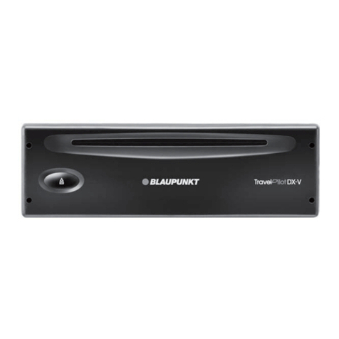
Blaupunkt TravelPilot DX-V User manual

Blaupunkt

Blaupunkt TravelPilot DX-V User manual

Blaupunkt PHILADELPHIA 865 User manual

Blaupunkt

Blaupunkt PHILADELPHIA 865 User manual

Blaupunkt BikePilot2 User manual

Blaupunkt

Blaupunkt BikePilot2 User manual

Blaupunkt TravelPilot RGS 08 User manual

Blaupunkt

Blaupunkt TravelPilot RGS 08 User manual

Blaupunkt TravelPilot RNS 3 User manual

Blaupunkt

Blaupunkt TravelPilot RNS 3 User manual

Blaupunkt New York 830 User manual

Blaupunkt

Blaupunkt New York 830 User manual

Blaupunkt TravelPilot Lucca 5.2 User manual

Blaupunkt

Blaupunkt TravelPilot Lucca 5.2 User manual

Blaupunkt TravelPilot 700 User manual

Blaupunkt

Blaupunkt TravelPilot 700 User manual

Blaupunkt SERIES 840 User manual

Blaupunkt

Blaupunkt SERIES 840 User manual

Blaupunkt TravelPilot 100 User manual

Blaupunkt

Blaupunkt TravelPilot 100 User manual

Blaupunkt NEW YORK 800 User manual

Blaupunkt

Blaupunkt NEW YORK 800 User manual

Blaupunkt CAPE TOWN 945 User manual

Blaupunkt

Blaupunkt CAPE TOWN 945 User manual

Blaupunkt TravelPilot RGN 08 User manual

Blaupunkt

Blaupunkt TravelPilot RGN 08 User manual

Blaupunkt ATLANTIS 945 User manual

Blaupunkt

Blaupunkt ATLANTIS 945 User manual

Blaupunkt TravelPilot Lucca 3.5 User manual

Blaupunkt

Blaupunkt TravelPilot Lucca 3.5 User manual

Blaupunkt TravelPilot 300 User manual

Blaupunkt

Blaupunkt TravelPilot 300 User manual

Blaupunkt TRAVELPILOT LUCCA 3.3 User manual

Blaupunkt

Blaupunkt TRAVELPILOT LUCCA 3.3 User manual

Blaupunkt TravelPilot DX-N User manual

Blaupunkt

Blaupunkt TravelPilot DX-N User manual

Blaupunkt TravelPilot 700 User manual

Blaupunkt

Blaupunkt TravelPilot 700 User manual

Blaupunkt TravelPilot User manual

Blaupunkt

Blaupunkt TravelPilot User manual

Blaupunkt TravelPilot RGN 08 Quick start guide

Blaupunkt

Blaupunkt TravelPilot RGN 08 Quick start guide

Blaupunkt DX-R52 User manual

Blaupunkt

Blaupunkt DX-R52 User manual

Blaupunkt 945 Series User manual

Blaupunkt

Blaupunkt 945 Series User manual

Popular Car Navigation System manuals by other brands

TomTom PRO 2020 user manual

TomTom

TomTom PRO 2020 user manual

Advanced ICE HD-G2 Update instructions

Advanced ICE

Advanced ICE HD-G2 Update instructions

PEUGEOT RT6 user manual

PEUGEOT

PEUGEOT RT6 user manual

Uniden Maptrax GPS352 user guide

Uniden

Uniden Maptrax GPS352 user guide

Mio Digiwalker C710 user manual

Mio

Mio Digiwalker C710 user manual

TomTom GO reference guide

TomTom

TomTom GO reference guide

Aceinna INS401 user manual

Aceinna

Aceinna INS401 user manual

Magellan 750NAV user manual

Magellan

Magellan 750NAV user manual

Subaru Navigation System owner's manual

Subaru

Subaru Navigation System owner's manual

Toyota DRG installation instructions

Toyota

Toyota DRG installation instructions

Pioneer CA-R-CG.001 manual

Pioneer

Pioneer CA-R-CG.001 manual

Pioneer AVIC-F30BT Important information for the user

Pioneer

Pioneer AVIC-F30BT Important information for the user

Hyundai IX35 owner's manual

Hyundai

Hyundai IX35 owner's manual

Glopex Networks GPS G53 user manual

Glopex Networks

Glopex Networks GPS G53 user manual

Volvo 31285222 installation instructions

Volvo

Volvo 31285222 installation instructions

Boss Audio Systems BV9382NV user manual

Boss Audio Systems

Boss Audio Systems BV9382NV user manual

GMC 2012 Terrain manual

GMC

GMC 2012 Terrain manual

Beyond FlipScreen owner's manual

Beyond

Beyond FlipScreen owner's manual

manuals.online logo
manuals.online logoBrands
  • About & Mission
  • Contact us
  • Privacy Policy
  • Terms and Conditions

Copyright 2025 Manuals.Online. All Rights Reserved.