manuals.online logo
Brands
  1. Home
  2. •
  3. Brands
  4. •
  5. Blaupunkt
  6. •
  7. Radio
  8. •
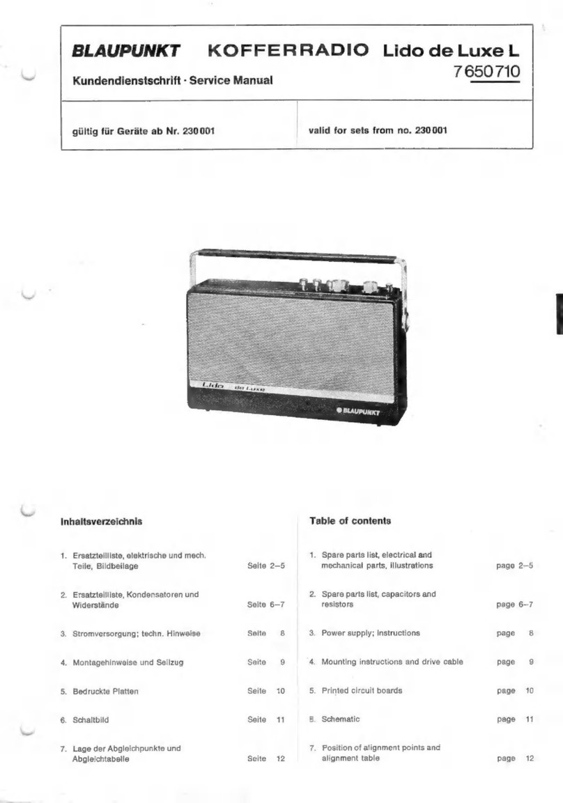
  9. Blaupunkt KOFFERRADIO Marimba User manual

Blaupunkt KOFFERRADIO Marimba User manual

Kundendienstschrift
-
Service
Manual
BLAUPUNKT
KOFFERRADIO
Marimba
7659500
gültig
für
Geräte
ab
Nr.
440001
valid
for
sets
from
No.
440
001
Inhaltsverzeichnis
1.
Ersatzteilliste,
elektrische
und
mechanische
Teile,
Abbildungen
Seite
2-
6
2.
Ersatzteilliste,
Kondensatoren
und
Widerstände
Seite
6-
8
3.
Technische
Hinweise
Seite
9-10
4.
Seilzug
Seite
10
5.
Lage
der
Abgleichpunkte
Seite
11
6.
Abgleichtabelle
Seite
11
7.
Gedruckte
Platten
Seite
12
8.
Schaltbild
Seite
13-14
Table
of
Contents
1.
Spare
parts
list,
electrical
and
mechanical
parts,
illustrations
page
2-
6
2.
Spare
parts
list,
capacitors
and
resistors
page
6-
8
3.
Technical
advice
page
9-10
4.
Drive
cable
page
10
5.
Position
of
alignment
points
page
11
6.
Alignment
table
page
11
7.
Printed
boards
page
12
8.
Schematic
page
13-14
Ersatzteilliste
Spare
Parts
List
Pos.
i.
Prels-
Bestell-Nr.
Schaltbild
gruppe
Bestellbezeichnung
Prici
Part
No.
Pos.
i.
`
schematic
group
Gehäuseteile
Housing
Parts
1
Gehäuse
ohne
Tragbügel,
Housing
without
carrying
handle,
8
655
220
061
V
ohne
Verp.
without
packing
2
|
Tragbügel
Carrying
handle
8
657
414
001
J
3
Skala
Dial
8
651
160
011
K
4
Führungsschiene
für
Skala
Guiding
strap
for
dial
8657
418
011
D
4a|
Führungsschiene
für
Zeiger
Guiding
strap
for
indicator
8
651
060
015
N
%
5
|
Markierungszeiger
Indicator
8
621
368
026
Mila
6
Firmenzeichen
Letters
8
671
115
043
B
7
|
Fußgleiter
Foot
slide
8
677
416
007
M
%
8
Batteriehalter
Battery
container
8
650
690
001
k
Gehàuseeinsatz
vollst.
Housing
set
compl.
8065
270371
`
Zusammen
M
Drehknopf,
klein
Knob,
small
8622090520
|
bestellen
B
Knopfhalter
Knob
holder
8631212023
f
order
F
%
Filzscheibe
Felt
washer
8630
150 487
`
together
E%
Drehknopf
für
Abstimmung
Knob
for
tuning
8622090580
|
zusammen
B
Knopfhalter
Knob
holder
8631
212023.
y
Bestellen
F
%
Filzscheibe
Felt
washer
8630
150 488
"order
G%
Lagerplatte
für
Klappe
Bearing
plate
for
flap
8651060000
together
Mile
Lagerbuchse
für
Klappe
Bearing
sleeve
for
flap
8
650
360
000
L%o
Verschlußführung
Locking
guide
8
657
462
001
Po
Verschlußstück
Locking
piece
8
657
462
011
Po
Druckfeder
Pression
spring
8
634
630 047
D%
Einlage
für
Verpackung
Interior
packing
for
packing
8
655 460
001
W
%
Verpackung
Packing
8
655 430
001
D
Bestückte
Gedruckte
Platten
Equipped
Printed
Circuit
Boards
HF/ZF/NF-Platte
RF/IF/AF
board
8
658
300
011
2
UKW-Platte
FM
board
8
658
300
041
Q
Trafo-Platte
Transformer
board
8
658
300
031
N
Potentiometer-Platte
Potentiometer
board
8
658 300
021
N
Drucktastensatz
Pushbutton
Switch
Miniaturflachtaste
8-teilig
Miniature
flat
button
8
parts
8
658 840
001
M
Kontaktschieber,
M,
L,
TA,
U,
Contact
slide,
M,
L,
PU,
U,
AFC
8
624
301
432
A
AFC
Kontaktschieber
Test
Contact
slide
Test
8
624
301
503
A
Kontaktschieber
Batt./Netz
Contact
slide
Batt./mains
8
624
301 431
A
Kontaktschieber
49
m
Contact
slide
49
m
8
624
301
434
A
Kontaktbriicke
mit
Feder
Contact
bridge
with
spring
8
624
300
101
M%
Druckfeder
für
Kontaktschieber
Pression
spring
for
contact
8
624
600
213
H
%
slide
Formfeder
fiir
Sicherungs-
Flat
spring
for
locking
slide
8
621
200 007
Po
schieber
Blattfeder
fúr
Arretierstift
Flat
spring
for
fixing
pin
8
621
200
005
G%o
Sicherungsblech
Locking
plate
8
621
300
518
N
%o
Halteblech
für
Blattfeder
Mounting
plate
for
flat
spring
8
620
100
205
co
Arretierstift
Fixing
pin
8
623 104
001
E
%
Tastenknopf
Pushbutton
8
622
090
091
A
Antriebsteile
Driving
Parts
Seilrolle
Idler
8
626
660
093
N
%
Seilrolle
klein
auf
Hebel
Idler,
small,
on
lever
8
626 610 013
N
9%
Antriebsrolle
auf
der
Abstimm-
Drive
pulley
on
tuning
shaft
8
626
660
101
Mile
achse
Antriebsrolle
auf
Drehko
Drive
pulley
on
variable
capacitor
8
626 660
105
Poo
Antriebsschnur
Drive
cord
6
766
111
016
Polo
Zeiger
Pointer
8
651
398
001
W
%
69
68
159
Pos.
i.
Prels-
Bestell-Nr.
Schaltbild
gruppe
Part
No.
Pos.
I.
Eros
schematic
group
Bestellbezelchnung
80
81
82
86
87
88
89
95
97
99
100
101
102
103
104
105
106
107
108
109
110
111
112
113
Antennen
Teleskopantenne
Ferritantenne
Antennenträger
LW-Spule
MW-Spule
Ferritstab
Netztell
Transformator
Sicherung
63mA
Sicherung
400
mA
Skalenlampe
7
V,
0,1
A
Lampenfassung
Kabelkasten
Spannungswähler
Sicherungshalter
Deckel
Netzkabel
mit
Stecker
Anzeigeinstrument
Halter
für
Anzeigeinstrument
Reflektor
(Lichtführung)
Abstimmtelle
UKW-Teil
vollst.
Drehkondensator
Puffer
Befestigungsschraube
Potentlometer
und
Einstellregler
Lautstärkeregler
200
ku
Höhenregler
250
k2
BaBregler
250
2
1,5
kQ
+
20—30
°/o
250
Q
Lautsprecher
Lautsprecher
Trinsistoren
AF
126
gelb
BF
341
BF
342
BF
343
BC
168
C
BC
262B
AC
187
K,
AC
188
K
paarig
AC
153
KT
AF
106
AF
121
Dioden
AA
112
AA
119
paarig
(Satz)
SFD
037
v20C2
2,8
ST
10
2,1
ST
10
BA
124
BYX
36/50
B
30
C
300
Antennas
Telescopic
antenna
Ferrite
antenna
Antenna
support
LW
coil
MW
coil
Ferrite
rod
Malns
Unit
Transformer
Fuse
63
mA
Fuse
400
mA
Dial
lamp
7
V,
0.1
A
Lamp
socket
Cable
container
Voltage
selector
Fuse
support
Cover
Mains
cord
with
plug
Indicator
Support
for
indicator
Reflector
(charging
guide)
Tuning
Parts
FM
unit,
compl.
Variable
capacitor
Cushion
Mounting
screw
Potentiometers
and
Adjusters
Volume
control
200
ku
Balance
control
250
kQ
Bass
control
250
Q
1.5
kQ
+
20-30
%o
250
2
Speaker
Speaker
Transistors
AF
126
yellow
BF
341
BF
342
BF
343
BC
168
C
BC
262
B
AC
187
K,
AC
188
K
by
pairs
AC
153
KT
AF
106
AF
121
Diodes
AA
112
AA
119
by
pairs
(set)
SFD
037
v20C2
2.8
ST
10
2.1
ST
10
BA
124
BYX
36/50
B
30
C
300
8
628 120
044
8
658
190
003
8
621
390
081
8
624
220
034
8
624 220
058
8
908
313
970
8
627
210
263
1
904
522719
1
904
522729
1
907
575
300
8
650
690
011
8
658
020
041
8
908
023
120
8
908
553 103
8
658
060
021
8
624
420
011
8
628
870
001
8
650
660
011
8
655
310
001
8
658
410
001
8
903
976 270
8
620
360
008
8
623
410
037
8
901
410
102
8
901
450
074
8
901
417
088
8
901
509
160
8
901
535
232
8
637
620
071
8
905
606
154
8
905
706
112
8
905
706
114
8
905
706
113
8
905
707
266
8
905
706
289
8
905 613
160
8
905
605
268
8
905
606
001
8
905
606
105
8
905
305
004
8
905
313 017
8
905
305
056
8
905
011
889
8
905 020
014
-8
905
020
013
8
905
405
063
8
905
405
801
8
905
013
174
T
181
Si
201,
202
Si203
LP
201
C
63,
64
R
175
R173
R
201
R
131
R
157
V
101
V
102
V
103
V
104
V
105
V
106
V
107,
108
V
109
v7i
V72
X71,
102
X
103,
104
X
105
X
106
X
101
X72
X73
X
181
X
182
ogwoun
r
NN
NNTIN
MOON
NNTN>
UNNN
115
116
117
118
119
120
121
122
123
124
125
126
127
128
129
130
131
132
133
134
135
136
137
|
138
139
140
141
142
143
144
145
146
147
148
149
150
151
152
155
156
157
158
159
160
Bestellbezeichnung
Spulen
und
Drosseln
KW-Vorkreisspule
Abstimmkern
KW-Oszillatorspule
Abstimmkern
MW-Oszillatorspule
Abstimmkern
UKW-Antennenspule
UKW-Zwischenkreisspule
Abstimmkern
UKW-Oszillatorspule
Abstimmkern
1.
FM/ZF-Filter
(Kollektorkreis)
Abstimmkern
1.
FM/ZF-Filter
(Basiskreis)
Abstimmkern
2.
FM/ZF-Filter
Abstimmkern
3.
FM/ZF-Filter
Abstimmkern
Ratiodetektor
Abstimmkern
Abstimmkern
Abstimmkern
1.
und
2.
AM/ZF-Filter
(Basiskreis)
Abstimmkern
2.
AM/ZF-Filter
(Kollektorkreis)
Abstimmkern
AM/ZF-Demodulator
Abstimmkern
Drossel
Emitterdrossel
Tiefpaßspule
Emitterdrossel
Drossel
Siebdrossel
Ferritperle
Ferritperle
Buchsen
und
Stecker
Lautsprecherbuchse
5-polige
Steckdose
TA/TB
Stecker
für
Lautsprecher
Stecker
5-polig
Antennenbuchse
mit
Träger
Trimmer
Trimmer
3......
9pF
Trimmer
4,5
Trimmer
10
.
AM/FZ-Filter
(Kollektorkreis)
Part
Coils
and
Chokes
SW
precircuit
coil
Iron
core
SW
oscillator
coil
Iron
core
MW
oscillator
coil
Iron
core
FM
antenna
coil
FM
intermediate
circuit
coil
Iron
core
FM
oscillator
coil
Iron
core
1.
FM/IF
transformer
(collector
circuit)
Iron
core
1.
FM/IF
transformer
(base
eircuit)
Iron
core
2.
FM/IF
transformer
Iron
core
3.
FM/IF
transformer
Iron
core
Ratio
detector
Iron
core
Iron
core
1.
AM/IF
transformer
(collector
eircuit)
Iron
core
1.
and
2.
AM/IF
transformer
(base
circuit)
Iron
core
2.
AM/IF
transformer
(collector
circuit)
Iron
core
AM/IF
demodulator
Iron
core
Choke
Emitter
choke
Low-pass
choke
Emitter
choke
Choke
Filter
choke
Ferrite
bead
Ferrite
bead
Jacks
and
Plugs
Speaker
jack
Wall-socket
PU/TR,
5-pole
Plug
for
speaker
Plug
5-pole
Antenna
jack
Trimmers
Trimmer
3......
9
pF
Trimmer
4.5
Trimmer
10
Bestell-Nr.
Part
No.
8
624 240 225
8
908 323
146
8
634
290 849
8
908 323
145
8
634
240
256
8
908 343 545
8
674
210
265
8
624 240
218
8
908 323
142
8
624
240
219
8
908
323
142
8
634
241
132
8
908 323
140
8
634 290 886
8
908 323
140
8
634
290
732
8
908
323
140
8
634
290 733
8
908
323
140
8
634
290
750
8
908
323
140
8
908
323
146
8
634 240
255
8
908 343 545
8
634
240 249
8
908 343
545
8
634
240
251
8
908 343
545
8
634
240 239
8
908
343 545
8
634
210
155
8
634
240 732
8
634
241 341
8
634
210
154
8
674
210 228
8
634
210
155
8
908 313
122
8
908 313
140
8
908
613
458
8
908 613
604
8
908 603 253
8
908 603 400
8
658 020
031
8
903
913
102
8
903
913
001
8
903 910 003
Pos.
i.
Preis-
Schaltbild
gruppe
Pos.
i.
Price
schematic
group
L1-L3
E
N
%o
L5-7
D
N
%
LI1-13
D
U
%
D71
Po
L71
B
N
%o
|
A
N
%
L73
A
N
%
L
15,
16
D
N
%
L
31-33
G
N
%
L
45—47
G
N
%
L
55—57
G
für
L
55
N
%
für
L
57
N
%
1521.22
D
U
%
L
26,
41
E
U
Die
L
35,
36
E
U
%
L
51,52
E
U
%
D
101
Ké
D
102
B
D
103
F
D72
Too
D
104
P
%
D
73
X
%
L
74
Je
L
201,
202
K%
Wie
X%o
vo
A
Cc
C
75,87
A
C8:
A
CA
V
Bestellbezeichnung
Bestell-Nr.
Pos.
i.
Schaltbild
Preisgruppe
Part
Part
No.
Pos.
i.
schematic
Price
group
Elektrolytkondensatoren
Electrolytic
Capacitors
2
uF
+
100—20
%
8
903 400
605
C
116,
122
2,2
uF
+
50-20
%
8
903
700 510
C
139
10
uF
+
50-20
%
8
903
700
215
C
150
10
uF
+
100-20
°/o
8
903
400
309
C
152
100
uF
+
50-20
%
8
903 405
312
C
151
500
uF
+
50-20
%
8
903 405
541
C
183
500
uF
+
50-20
%0
8
903 402
314
C
147,
154,
155,
181,
182
Keramische
Kondensatoren
Ceramic
Capacitors
3,5
pF
+
0,2
pF
8
902 235
001
C
86
5
pF
+
0,5
pF
8
902
250
025
C
74,78
10
pF
+
0,5
pF
8
902
210
143
C
88
18
pF
+
5%
8
902
218
101
C
71
22pE
#:5%
8
902 222
106
c79
51
pF
+
2%
8
902
251
103
C85
180
pF
+
2%
8
902
218
208
C
80
220
pF
+
5%
8
902
222
227
C
144
330
pF
+
50—20
°/o
8
902
233
227
C
201
330
pF
+
20%
8
902
233
220
C
127
470
pF
+
10%
8
902 247 235
C
81,
91,
137,
138
1
nF
+
20%
8
902
210 381
C72
1,5
nF
+
50-20
%
8
902
215
301
C
140
2,2
nF
+
50—20
%o
8
902 222
301
C
131
4,7
nF
+
50—20
fie
8
902
247
301
C
104
4,7
nF
+
80—20
%
8
902 247 327
C
126
10
nF
+
80—20
°/o
8
902
210
440
C
136
10
nF
+
80-20
%
8
902
210
426
C73
Tele
I
I+
I+
I+
Ich
ele
+
Kunstfolienkondensatoren
Plastic
Film
Capacitors
82
pF
+
2,5%
8
902
730
223
C
101,
110
250
pF
+
2,5%
8
902 730 365
©
111
300
pF
+
2,5
%V
8
902
730
236
C115
360
pF
+
2,5%
8
902
731
238
C
153
390
pF
+
2,5%
8
902
731
239
C172
15n
5%
8
902
704 453
C
89
2n
5%
8
902
731
456
C
174
3,3n
25%
8
902
710
261
C
134,
135
4,7n
2,5
%
8
902 704 265
C
102
6,8
n
2,5%
8
902 704 269
C
108
10nF
+
20%
8
902
913 601
C
130,
133,
173
10nF
+
20%
8
902
941 601
C
128
15nF
+
10%
8
902
913
305
C
109
22nF
+
10%
8
902 913 309
C
119,
175
22nF
+
20%
8
902
810
481
C
105
47
nF
+
20%
8
902
913 617
C
118, 125,
145
47
nF
+
20%
8
902
931
717
C
124
68
nF
+
20%
8
902 913
621
C
146,
171
0,1
uF
+
20%
8
902
913
625
C
129
0,68
uF
+
20%
8
902
913 645
C
143
Schichtwiderstände
Composition
Resistors
15
5%
0,125
W
8
900
305
151
R
147
33
+
10%
0,3
W
8
900
401 331
R
183
120
+
10%
0,125
W
8
900
303
122
R
143
150
+
10%
0,125
W
8
900
303
152
R
159
330
+
10%
0,125
W
8
900
303
332
R
154,
182
390
£-
5%
0,125
W 8
900
305
392
R
108,
116,
158
470
+
5%
0,2
W
8
900
301
472
R
76
Bestellbezeichnung
Part
Bestell-Nr.
Part
No.
Pos.
i.
Schaltbild
Pos.
i.
schematic
Preisgruppe
Price
group
+
0,125
W
8
900 303 472
R
109,
129
P/a
223
680
Q+
5%
0.2.5
WV.
8
900
301
682
R72
P®%
224
820
Q
+
10%
0,125
W
8
900
303
822
R
126
Poo
225
1kQ
+
10%
0,125
W
8
900 303
103
R
112,
146
Poo
226
1,2k2
+
10%
0,125
W
8
900
303
123
R115
Po
227
12k2
+
5%
02
W
8
900
301
123
R73
Poo
228
1,5
kQ
+
10%
0,125
W
8
900 303 153
R
130
P
Yo
229
2,7
kQ
+
10%
0,125
W
8
900 303 273
R
103
Poo
230
27kQ+
5%
0,2
W
8
900
301
273
R71,
152
Po
231
3,3
kQ
+
10%
0,125
W
8
900
303 333
R
105, 136,
151,
160
P
%
232
3,9
kQ
+
10%
0,125
W
8
900 303 393
R
172,
181
Poo
233
4,7
kQ
+
10%
0,125
W
8
900 303
473
R111
Poo
234
5,6
kQ
+
10%
0,125
W
8
900
303
563
R
102, 118,
119,
125
Pi
235
8,2k2
+
5%
0,2
W
8
900
301
823
R74
Rs
236,
10
kQ
+
10%
0,125
W
8
900
303
104
R
101,
117,
122,
123,
Poo
174
237
10k2
+
5%
0,2
W
8
900
301
104
R78
Poo
238
12kQ
+
10%
0,125
W
8
900
303
124
R
124
Poo
239
15kQ
+
5%
0,2
W
8
900
301
154
R75
Po
240
15kQ
+
10%
0,125
W
8
900
303
154
R
132,
133,
171
Poo
241
39k2
+
10%
0,125
W
8
900 303
394
R
127,
150
Pia
242
47kQ
+
5%
0,2
W
8
900
301
474
R77
Poo
243
47
kQ
+
10%
0,125
W
8
900
303
474
R
139
P
9%
244
82kQ
+
5%
0,125
W
8
900 305 824
R
140
Poo
245
100
kQ
+
10%
0,125
W
8
900
303
105
R
137,
144
Po
246
150
kQ
+
10%
0,125
W
8
900 303
155
R
104,
145
Po
247
220
kQ
+
10%
0,125
W
8
900 303
225
R
110
P%o
248
330
kQ
+
10%
0,125
W
8
900
303 335
R
138
Po
NTC-Widerstand
NTC
Resistor
130
Q
20
in
8
901
325 015
Sicherungslasche
Nase
Locking
Nose
Fig.
1
Technische
Hinweise
1
Stromversorgung
Das
Gerät
wird
aus
6
Mono-Zellen
gespeist,
die
im
Gerät
untergebracht
sind.
Die
Betriebsspannung
beträgt
9
V.
Als
Ersatz
nur
1,5
V
Mono-Zellen
„Leak
proof“,
35
mm
®,
ver-
wenden.
Das
Gerät
ist
mit
einem
festeingebauten
Netzteil
ausgerüstet
und
kann
in
Verbindung
mit
dem
Netzkabel
an
220
oder
110
V
Wechselspannung
angeschlossen
werden.
Mit
der
Taste
Batterie/Netz
kann
das
Gerät
wahlweise
mit
Batterie
oder
Netz
betrieben
werden.
Wird
das
Gerät
nur
mit
Netzteil
betrieben,
so
empfehlen
wir,
die
Batterien
aus
dem
Gerät
herauszunehmen.
Zur
Stromversorgung
des
ausgebauten
Chassis
können
auch
die
6
Mono-Zellen
verwendet
werden.
2
Ausbau
des
Chassis
2.1
Bedienungsknöpfe
abziehen.
2.2
Rückwand
herunterklappen
und
Batteriehalter
heraus-
nehmen.
2.3
Die
4
Befestigungsschrauben
der
Kunststoffabdeckung
und
je
eine
Chassisschraube
unten
rechts
und
am
Ge-
häuseboden
entfernen.
2.4
Chassis
nach
hinten
herausziehen
und
Kunststoffabdek-
kung
nach
oben
abziehen.
3
Auswechseln
eines
Drucktastenschlebers
3.1
Chassis
ausbauen.
3.2
Skala
abschrauben.
3.3
Mit
einer
Spitzpinzette
die
Sicherungslasche
am
Druck-
tastenschieber
der
Taste
„K“
nach
vorn
aushaken
(Fig.
1).
3.4
Durch
leichten
seitlichen
Zug
(ca.
1
mm)
an
der
Nase
des
Sicherungsschiebers
(Fig.
1)
erfolgt
die
Entriegelung
der
8
Tasten
(Tasten
festhalten!).
3.5
Gewünschten
Tastenschieber
herausziehen
und
aus-
wechseln.
3.6
Nach
gleichzeitigem
Hinunterdrücken
aller
8
Tasten
Sicherungslasche
wieder
einhaken.
120
0,47uF
[`
F=
ES
5,6
MeBsender
Signal
generator
Fig.
2
Technical
Advice
1
Power
Supply
The
set
is
operated
with
6
flashlight
cells
which
are
placed
in
the
set.
The
supply
voltage
is
9
V.
For
replacement
use
only
D-size
cells
“leak
proof“,
1.5
V,
17/s
inches
Ø.
The
set
contains
a
mains
unit
and
with
the
mains
cord
can
be
connected
to
220
V
or
110
V
mains
voltage.
The
button
battery/mains
serves
for
alternatively
connecting
the
set
to
the
batteries
or
to
the
mains.
If
the
set
is
to
be
used
with
the
mains
unit
only,
we
recom-
mend
to
remove
the
batteries.
The
6
flashlight
batteries
can
also
be
used
as
power
supply
if
the
chassis
has
been
removed
out
of
the
housing.
2
Removal
of
Chassis
2.1
Pull
off
control
knobs.
2.2
Remove
rear
panel
and
battery
compartment.
2.3
Remove
the
4
mountnig
screws
of
the
plastic
cover
and
one
chassis
screw
each
from
the
RH
side
below
and
the
bottom
of
the
housing.
2.4
Remove
chassis
and
take
off
plastic
cover
in
upward
direction.
3
Exchange
of
a
Pushbutton
Rod
3.1
Remove
chassis.
3.2
Unscrew
dial.
3.3
With
a
pair
of
tweezers
release
the
locking
at
the
rod
of
the
pushbutton
„K“,
see
fig.
1.
3.4
By
pulling
slightly
sideways
(approx.
0.04”)
at
the
nose
of
the
securing
slide
(see
fig.
1)
disengagement
of
the
8
pushbuttons
takes
place
(retain
pushbuttons!).
3.5
Remove
the
respective
pushbutton
rod
and
replace
it
by
a
new
one.
3.6
By
pressing
the
8
pushbuttons
simultaneously
reengage
locking.
4.1
4.2
4.3
4.4
4.5
4.6
5.1
5.2
5.3
5.4
6.1
6.2
6.3
6.4
6.5
AM-Abgleich
Die
Betriebsspannung
soll
9
V
betragen.
MeBsender
und
Empfånger
erden.
Zeiger
mit
der
Eichmarke
in
Deckung
bringen.
(Linke
Skalenseite).
Outputmeter
(Ri
2
100
2)
parallel
zum
eingebauten
Lautsprecher
anschließen.
50
mW
=
0,5
.V
am
Output-
meter.
Lautstårkeregler
auf
Maximum,
Sopranregler
auf
„hell“,
BaBregler
auf
„dunkel“.
Beim
AM-Abgleich
künstliche
Antenne,
Fig.
4,
verwen-
den.
FM-Abgleich
Durch
Drehen
der
AFC-Taste
automatische
Scharfab-
stimmung
ausschalten.
Beim
FM-Abgleich
ein
hochohmiges
Voltmeter
(Ri
>
50
k2/V
parallel
zu
C
139
anschließen,
(6)
Fig.
6.
Angegebene
Reihenfolge
der
Abgleichelemente
ein-
halten.
Abgleich
so
lange
wiederholen,
bis
keine
Verbesserung
mehr
erzielt
wird.
Einstellung
des
Kollektorruhestromes
Die
Betriebsspannung
soll
9
V
betragen.
Vor
der
Ruhestrom-Einstellung
das
Gerät
ca.
1
Std.
bei
Prüfraum-Temperatur
lagern.
In
die
gemeinsame
Kollektorleitung
beider
Endtransi-
storen
((7)
Fig.
6)
ein
Milliamperemeter
schalten
(Mul-
tavi
V,
MeBbereich
15
mA).
Lautstarkeregler
auf
Minimum.
Den
Ruhestrom
ca.
1
Minute
nach
dem
Einschalten
des
Gerätes
mit
dem
Einstellregler
R
157
(Fig.
5)
auf
4
mA
+
20
—
10
%
einstellen.
Fig.
3
4.1
42
4.3
44
4.5
4.6
5.1
5.2
5.3
5.4
6.1
6.2
6.3
6.4
6.5
Ta
7.2
FA
7.2
=
10
AM
Alignment
Operating
voltage
should
be
9
V.
Ground
signal
generator
and
set.
Line
up
pointer
with
LH
end
calibration
of
dial.
Connect
outputmeter
(Ri
>
100
Q)
in
parallel
to
built-in
speaker.
50
mW
=
0.5
V
output.
Volume
control
to
maximum,
treble
control
to
“treble“,
bass
control
to
"base",
For
AM
alignment
use
dummy
antenna,
see
fig.
4.
FM-Alignment
Cut
out
automatic
frequency
control
by
turning
AFC
button.
For
FM
alignment
connect
voltmeter
(Ri
>
50
kQ/V)
in
parallel
to
C
139
(6)
Fig.
6.
Follow
alignment
sequence
carefully.
Repeat
alignment
until
no
further
improvement
can
be
obtained.
Setting
Collector
Zero
Signal
Current
The
operating
voltage
should
be
9
volts.
Previous
to
setting
collector
zero
signal
current
store
set
at
test
room
temperature
for
approx.
1
hour.
Connect
an
ammeter
(Multavi
V,
measuring
band
15
mA)
to
the
combined
collector
lead
of
both
output
transi-
stors
(<7)
fig.
6).
Turn
volume
control
to
minimum.
Approx.
1
minute
after
switching
on
set,
adjust
zero
signal
SCH
via
adjuster
R
157
(fig.
5)
to
4
mA
+
20
—
10
Die,
Auswechseln
des
Skalenseils
Chassis
ausbauen.
Skalenseil
(Lange
ca.
0,8
m)
nach
Fig.
3
auflegen.
Exchange
of
the
Drive
Cable
Remove
chassis.
Place
drive
cable
as
shown
in
fig.
3
(length
approx.
32”).
Ð
=
Fig.
4
Meßsender
Signal
generator
Abgleichtabelle
Wellenbereiche:
87,4
—
108
MHz
5,98—
6,25
MHz
515
—
1640
kHz
18
—
255
kHz
UKW
Kw
MW
LW
3,43
—
2,78m
50,20—
48
m
584
—
182
m
1176
—2040
m
Bereich
MeBsender
Skalenzeiger
Waveband
Sign.
Gen.
Pointer
über
Spannungsteiler
Fig.
2
Alignment
Table
Wavebands:
87.4
—
108
MHz
5.98
—
`
6.25
MHz
5155
—
1640
kHz
148
—
255
kHz
3.43
—
2.78
50.20
—
48
584
—
182
1176
—
2040
UKW
Kw
MW
m
m
m
LW
m
HF
Empfindlichkeit
bezogen
bei
AM
auf
50
mW
Ausgangsistg.;
FM
auf
0,5
V
Ratiospannung
RF
sensitivity
on
AM
for
50
mW
output;
FM
for
0.5
V
ratio
voltage
Abgleichelemente
Trimming
points
ab
Basis/from
base
V
101
(3)
über
Spannungsteiler/via
voltage
divider
20:1
0,46
3)
(0,452)
via
voltage
divider
Fig.
2
1600
M
(ZF
/
IF)
ab
from
(3)
L
51,
L
41,
L
35,
L
26,
L
21
auf
Maximum
/
to
maximum
ca./approx.
400
uV
bei
M
und
L
im
homogenen
Feld
on
M
and
L
in
homogeneous
field
Vorkreis
Pre.
circ.
Oszillator
Oscillator
ca./approx.
60
uV/m
ca./approx.
25
uV/m
über
1
nF
an
(4)
via
1
nF
to
(4)
über
60
Q
Kabel
via
60
2
cable
Zwischenkreis
ca./approx.
200
uV/m
ca./approx.
90
uV/m
ca./approx.
4uV
über
Spannungsteiler/via
voltage
divider
10:1
L
57,
L
55,
L
46,
L
45,
L
32,
L31,
L
15,
L
73
auf
max.
Ratiospannung
to
max.
ratio
voltage
')
R
131
auf
to/Min.
Outputmeter|
ab
Basis/from
base
V
102
L
15
verstimmen/detune
L
15
ca./approx.
400
“V
ab
Antennenanschluß
Oszillator
f
Int.
circ.
Oscillator
from
antenna
connection
Antenne/antenna
1)
Ein
AM-Signal,
400
Hz,
30°/o
moduliert,
soll
eine
Ratio-
spannung
von
1,0
V
erzeugen.
Dann
mit
R
131 ein
Span-
nungsminimum
am
Outputmeter
einstellen,
Fig.
5.
2)
Koppelspule,
ca.
20
Windungen,
6
cm
Durchmesser,
an
das
MeBsenderkabel
anschließen
und
in
die
Nähe
des
Ferritstabes
bringen.
Abgleich
nach
der
Abgleichtabelle.
3)
Bei
Geräten
mit
besonderer
Kennzeichnung
AM
ZF
452
kHz
=
0,452
MHz.
ca./approx.
2
uV
|
1)
An
AM
signal,
400
Hz,
30%
modulated,
must
produce
a
ratio
voltage
of
1.0
V.
Adjust
a
voltage
minimum
at
the
outputmeter
by
means
of
R
131,
see
fig.
5.
2)
Connect
coupling
coil,
approx.
20
wdgs.,
2.36”
(h
to
cable
of
signal
generator
and
approach
the
coil
to
ferrite
an-
tenna.
Align
according
to
alignment
table.
3)
For
sets
with
special
indication
IF
AM
452
kHz
=
0,452
MHz.
Lage
der
Abgleichpunkte
/
Position
of
Alignment
Points
ENG
e
o
c87
L72
om)
R131
L57
[K1091]
Silt
oe
Die
AnschluBpunkte
neben
den
Platten
sind
durch
Zahlen
Connection
points
on
the
boards
are
marked
by
numbers
gekennzeichnet
und
stimmen
mit
denen
im
Schaltbild
über-
|
which
correspond
to
those
in
the
schematic.
ein.
|
HF-ZF-NF-Platte
/
RF-IF-AF
Board
Bedruckungsseite
/
printed
side
Fig.
6
Trafoplatte
/
Transformer
Board
Potentiometer-Platte
/
Potentiometer
Board
UKW-Platte
/
FM
Board
Bedruckungsseite
/
printed
side
Bedruckungsseite
/
printed
side
Bestiickungsseite
/
components
side
Fig.
7
:
21ST10
e?
Ta
En
125/0,46/1,750
Schalterdiagramm/Switch
diagram
Diagramme
du
commutateur
TA
y
AFC
i
Best.Nr./Part
nos./Ref.
v
101
8
905
606
154
v
102
8
905 706
112
Testing
Do
M
49m
k
v
103
8
905
706
114
V
106
8
905 706
113
A
d
hoe
eke.
oral
V
105
8.905
707
266
1
eects
`
Lat
SE
2030
Ie
se
V
107,108
8
905
613
160
v
109
8
905
605
268
30
e
ee
o
o
see
o
e
va
3
905
606
001
vn
305
606
105
iR
x
71,102
8
$05
305
004
X
103,104
_
8
905
313
017
e
X
105
8
905
305
056
X
106
8
905
011
869
Gezeichnete
Schalterstellung:
U
x
10t
8
905
020
014
Shown
Position:FM
xR
INIA
Position
dessinée:
FM
x
73
8
905 405
062
x
181
4
905
405
801
X
182
8
905
013
174
R
175
8
901
410
101
Ram
8
901
450
074
R
201
8
901
417
088
R
131
8
901
509
123
R
157
8
901
535
232
Si
201,202
1
904
522719
Si
203
1
904
522
729
LP201
21GL
0701/01z
Bass
Sopran
Bass
control
Treble
control
Contréle
des
graves
Contröle
des
aigus
Ka),
=
45
I
o
p
A
Lautstärke
Volume
control
Contröle
de
volume
160/0,45/2]0
retarc
110/2204
Bereich|
Schwingspannung
|
Gemessen
mit
RV
an
Osc.
voltage
|
Measured
with
VTVM
a
Gamme]
Tensión
oscill.
|Mesuree
avec
voltm.
a
lampesa
80-120mV
70-110
mV
80
120
mV
70-150
mV
Für
Werte
ohne
Bezeichnung
pF
oder
fi
einsetzen.
Read
pF
or
Q,respectively,
unless
otherwise
noted.
Pour
les
valeurs
sans
indikation
lire
pF
oun.
Änderungen
vorbehalten!
Modificatior
141
R108
390
(R137
(look
v20C2
R109
W470
Boow/ısv
ae
1181
a
g
e
as
Qe
23
B30C300
A
$1202
63mA
träge
slow
blow
retarde
Im
ssenmitRVan
ured
with
VTVM
at
ree
avec
voltm.
i
lampesä
ern
einsetzen.
iherwise
noted.
re
pF
oun.
V102,V
103,
v104
Modifications
reserved!
400mA
träge
10p/10V
stow
sow
AC153KT
Hee
retardé
150k
Belastbarkeit
/
Rating/
Charge
maximum
===
Ye
W
Y5W
1⁄3W.
2W
Ferriiperle
Ferrite
bead
Perle
ferrite
Nennspannung/Nominal
voltage/
Tension
nominale
JE
AR
AR
E
AF
<250V
250v
400V 500V
Toleranz
Elko
Tolerance
Electrol.cap.
-4,8V
el
Tolerance
Cond.chimique
225%
Transistoranschlüsse/Transistor
connections/Raccordements
des
transistors
Modifications
reservéest
v105
B
ECB
c
B
B,
c E
E
B c
E
H
E
E
B s
E s
V107,
V108,
v106
v72,
vai
v109
v101
mare:
AC188
Gleichspannungen
Tol.
+15%
mit
Röhrenvoltmeter
Riz
10MO
gegen
Plusspannung
gemessen
(ohne
Signal)
DC.
voltages
tol.*
15%
measured
with
VTVM
Ri
e
10MQ
to
positive
voltage
(without
signal)
Tensions
CC
tol.+15%
avec
voltmétre
à
lampes
Riz10MO
à
tension
positive
(sans
signal)
+20%
4mA
L
10%
Einstellbar
mit
R157
Adjust
with
R157
Régler
avec
R157
9
7
659
500
Notizen
/
Notes
Anderungen
vorbehalten!
Nachdruck
—
auch
auszugsweise
—
nur
mit
Quellenangabe
gestattet
Blaupunkt-Werke
GmbH,
Hildeshelm
-
Mitglied
der
Bosch-Gruppe
Printed
in
Germany
by
Hagemann-Druck,
Hildesheim
Moditications
reserved!
Reproduction
—
also
by
extract
—
only
permitted
with
indication
of
authorities
used
KDB
570.
04.
006.
20
A

This manual suits for next models

1

Other Blaupunkt Radio manuals

Blaupunkt Derby H User manual

Blaupunkt

Blaupunkt Derby H User manual

Blaupunkt oslobludab User manual

Blaupunkt

Blaupunkt oslobludab User manual

Blaupunkt Phoenix MP33 User manual

Blaupunkt

Blaupunkt Phoenix MP33 User manual

Blaupunkt BCR-9 DABi User manual

Blaupunkt

Blaupunkt BCR-9 DABi User manual

Blaupunkt Lido L 7659310 User manual

Blaupunkt

Blaupunkt Lido L 7659310 User manual

Blaupunkt BREMEN SQR 46 User manual

Blaupunkt

Blaupunkt BREMEN SQR 46 User manual

Blaupunkt HR50DAB User manual

Blaupunkt

Blaupunkt HR50DAB User manual

Blaupunkt RX+ 35e User manual

Blaupunkt

Blaupunkt RX+ 35e User manual

Blaupunkt PP5BR User manual

Blaupunkt

Blaupunkt PP5BR User manual

Blaupunkt IR50DAB User manual

Blaupunkt

Blaupunkt IR50DAB User manual

Blaupunkt PR4 User manual

Blaupunkt

Blaupunkt PR4 User manual

Blaupunkt PP20 User manual

Blaupunkt

Blaupunkt PP20 User manual

Blaupunkt OSLO User manual

Blaupunkt

Blaupunkt OSLO User manual

Blaupunkt PP15DAB User manual

Blaupunkt

Blaupunkt PP15DAB User manual

Blaupunkt KV 900 User manual

Blaupunkt

Blaupunkt KV 900 User manual

Blaupunkt KR12SL User manual

Blaupunkt

Blaupunkt KR12SL User manual

Blaupunkt BR-80DABC User manual

Blaupunkt

Blaupunkt BR-80DABC User manual

Blaupunkt BB11BK User manual

Blaupunkt

Blaupunkt BB11BK User manual

Blaupunkt BR-90DABi User manual

Blaupunkt

Blaupunkt BR-90DABi User manual

Blaupunkt Sirius America SR04 User manual

Blaupunkt

Blaupunkt Sirius America SR04 User manual

Blaupunkt Lido de Luxe L User manual

Blaupunkt

Blaupunkt Lido de Luxe L User manual

Blaupunkt PP16DAB EDITION User manual

Blaupunkt

Blaupunkt PP16DAB EDITION User manual
Blaupunkt BA-10 Installation and operation manual

Blaupunkt

Blaupunkt BA-10 Installation and operation manual

Blaupunkt PP11BT User manual

Blaupunkt

Blaupunkt PP11BT User manual
Popular Radio manuals by other brands

Clas Ohlson MR-332 instruction manual

Clas Ohlson

Clas Ohlson MR-332 instruction manual

Motorola GP360 Series user guide

Motorola

Motorola GP360 Series user guide

Tivdio V-112 user manual

Tivdio

Tivdio V-112 user manual

Pioneer XMp3 user guide

Pioneer

Pioneer XMp3 user guide

Raymarine Ray240 installation guide

Raymarine

Raymarine Ray240 installation guide

Entel HT446E Technical Support Bulletin

Entel

Entel HT446E Technical Support Bulletin

XHDATA D-608 user manual

XHDATA

XHDATA D-608 user manual

Goodmans 365112 user manual

Goodmans

Goodmans 365112 user manual

Baofeng UV-5RV2+ operating manual

Baofeng

Baofeng UV-5RV2+ operating manual

LENCO PDR-030 user manual

LENCO

LENCO PDR-030 user manual

auna Intelligence manual

auna

auna Intelligence manual

RIDGID R84087 Operator's manual

RIDGID

RIDGID R84087 Operator's manual

Maxon TJ-3000 Series user manual

Maxon

Maxon TJ-3000 Series user manual

Manta CB02 user manual

Manta

Manta CB02 user manual

AUDAC IMP40 user manual

AUDAC

AUDAC IMP40 user manual

Sencor SRD 7800 user manual

Sencor

Sencor SRD 7800 user manual

Kenwood TH-D72A Service manual

Kenwood

Kenwood TH-D72A Service manual

Teac SL-D900BT owner's manual

Teac

Teac SL-D900BT owner's manual

manuals.online logo
manuals.online logoBrands
  • About & Mission
  • Contact us
  • Privacy Policy
  • Terms and Conditions

Copyright 2025 Manuals.Online. All Rights Reserved.