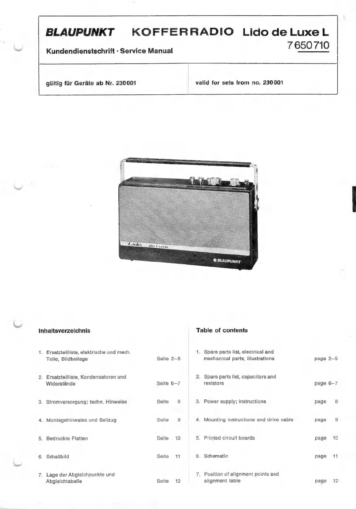
Blaupunkt Lido de Luxe L User manual
Other Blaupunkt Radio manuals

Blaupunkt
Blaupunkt oslobludab User manual

Blaupunkt
Blaupunkt IR50DAB User manual

Blaupunkt
Blaupunkt KOFFERRADIO Marimba User manual

Blaupunkt
Blaupunkt PP20 User manual

Blaupunkt
Blaupunkt BD-320 User manual

Blaupunkt
Blaupunkt BB11BK User manual

Blaupunkt
Blaupunkt BTA-6000 User manual

Blaupunkt
Blaupunkt KC BT 25 User manual

Blaupunkt
Blaupunkt RX 19e User manual

Blaupunkt
Blaupunkt A-R G 01-E User manual

Blaupunkt
Blaupunkt RX 19-1 User manual

Blaupunkt
Blaupunkt BCR-9 DABi User manual

Blaupunkt
Blaupunkt PP5BR User manual

Blaupunkt
Blaupunkt Phoenix MP33 User manual

Blaupunkt
Blaupunkt HR50DAB User manual

Blaupunkt
Blaupunkt BR-90DABi User manual

Blaupunkt
Blaupunkt Sirius America SR04 User manual

Blaupunkt
Blaupunkt IR10BT User manual

Blaupunkt
Blaupunkt KV 900 User manual

Blaupunkt
Blaupunkt BREMEN SQR 46 User manual