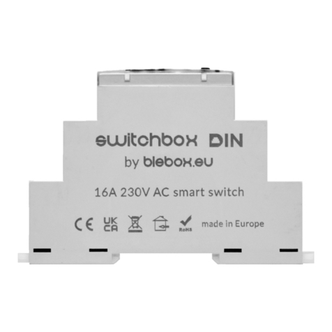
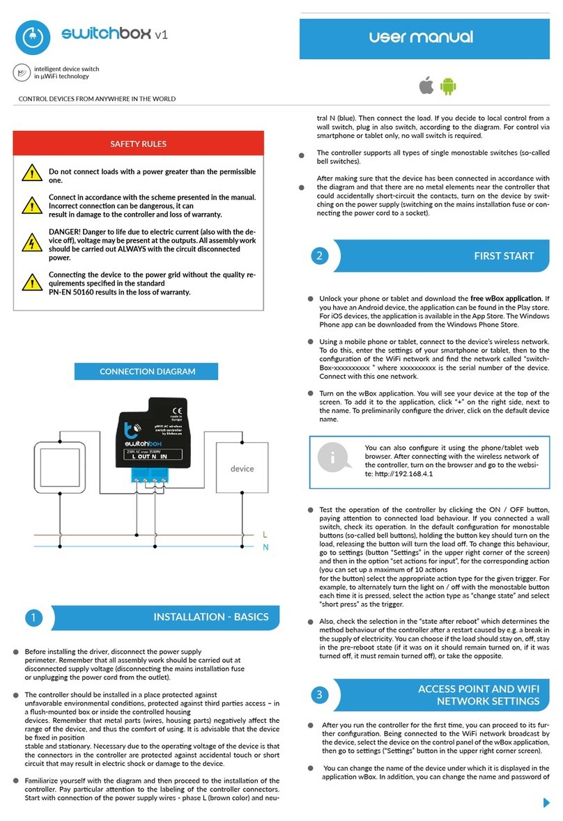
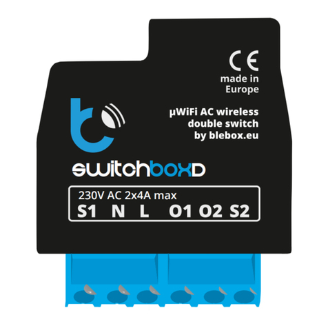
BleBox switchboxD DIN User manual

switchboxDDIN
WIRELESS DOUBLE SWITCH 230V WITH ENERGY CONSUMPTION
MEASUREMENT, DIN RAIL MOUNT
control with μWiFi technology
from any place in the World
values.
Connect only in accordance with the diagram presented in the
1
Disconnect the installaon supply voltage before installing the
controller. Remember that any mounng works should be carried
out when the mains voltage is disconnected (switch o the
mains fuse or disconnect the power cord from the mains socket).
The controller should be installed on the DIN rail, protected from third party
access - in the ush box or inside the enclosure of the controlled device.
Remember that metallic elements (wires, housing parts) have a negave
inuence on the range of the device, and consequently the comfort of use. It
is recommended that the device be mounted in a stable and xed posion.
Due to the operang voltage of the device it is necessary that the connectors
of the controller be protected against accidental contacts or short circuits,
which could cause electric shock or damage to the device.
Read the diagram and then proceed to install the controller. Pay parcular
aenon to the designaon of the controller connectors. Start with power
wires - phase L (usually brown) and neutral N (blue). Then, connect the load.
If you only want a local control with a wall switch, connect the wall push-
buon according to the diagram. To control using only your phone or Tablet,
it is not necessary to install the wall push-buon.
user manual

Aer making sure that the device is connected in accordance with the
diagram and that there are no metal components near the controllerwhich
may accidentally cause short-circuit, start the device by turning on the power
(turning on the mains fuse or connecng the power cord to the power outlet).
2
4
5
DownloadIf you have an Android mobile device,
you will nd the applicaon in the Play Store. For iOS devices the applicaon
is in the App Store.
By using your mobile phone or tablet, connect it to the device wireless
network. To do this, enter to your smartphone or tablet sengs, then go to
seng of the WiFi network and nd the network name „switchBoxD_DIN-
xxxxxxxxxx” where xxxxxxxxxx is the serial number of the device. Connect
to this network.
Turn on the wBox applicaon. You will see your device on the main screen.
In order to add it to your applicaon account, select “Add device to account”.
If you are the installer and do not want to assign the device to your account,
select “Use only once”.
Test the operaon of the controller by pressing the ON/OFF buon in the
app, paying aenon to the behavior of the connected load and backlight in
the controller. You can also control the load using the buon located on the
controller housing - have in mind that it will toggle both outputs. If you have
connected a wall switch, check its operaon. The default conguraon is
designed to work with bistable buons (rocker switch). In this conguraon,
for monostable buons (push-buons), holding down the push-buon
should turn on the load, releasing will turn o the load. Changing the acon
sengs is described in the further part of the manual.
You can also set the conguraon using the web
browser of your phone / tablet. Aer connecng to the
wireless network of the controller, turn on the browser
and go website www.blebox.eu
3
Go to the WiFi network sengs (“Sengs” icon in the top right corner of
the screen, “Connecon” secon), where you can connect the device to the
home WiFi network to be able to control the device via it or from anywhere
in the world. To do this, select the network name from the list of available
networks and press “Connect”. If required, enter your WiFi password.
When connecng the device to the home network, the phone / tablet may
disconnect from the device’s network.
Aer reconnecng the phone to the controller’s WiFi network, check the
“WiFi Client status” and “Remote access status” elds. The controller is
equipped with a network connecon supervision system which in case of
problems with connecon to the WiFi or the Internet will report the problem
and its possible causes. If the network is working properly both elds will be
set to “Connected”.
In order to communicate with the device from outside the local WiFi
network, from anywhere in the world, via the wBox applicaon, the device
automacally connects to the BleBox cloud system service by default. The
remote access system is fully encrypted and secure, the data are transmied
by European servers from reputable companies. It is possible to disable
the remote access service - aer clicking the “Congure” buon, toogle
the switch next to the “Remote access” opon. Remember that disabling
“Remote access” will result in no access to the controller from outside the
local network as well as disabling the nocaons and external integraon
systems, therefore we recommend that you leave this opon enabled (default
seng). event log
Enabling the “Event log” opon will cause the device to record events (e.g.
about sent nocaons set in the “Acons” secon) in the BleBox cloud
system. This allows the history of the events to be viewed later also when
the controller is oine.
Aer compleng the WiFi network conguraon, you can disconnect from
the device network and connect the phone / tablet directly to your home
WiFi network. Control from the wBox applicaon will work in the same way
as when the phone / tablet is connected to the device’s network. If as a
user you leave the local network, eg leaving your home or enclosing mobile
data, the wBox applicaon will signal this status as “Remote mode”. In this
case, you will have access to the device data, but for security reasons sengs
opons will not be available.
In the “”Service connecon (AP)”” secon, you can change the name and
give the password of the WiFi network emied by the device. Remember
that changing the network name or password can cause disconnecon with
the device immediately aer clicking the “”Save”” buon, so you should
reconnect to the WiFi network.
It is also possible to completely disable the access point emied by the
device. To do this move the “Access point” slider to the o posion and
conrm the selecon with the “Save” buon.
Aenon! If the controller does not have a stable connecon to the WiFi
network (“WiFi client status”: “Connected”, without any error warnings),
restarng the access point will not be possible - in this situaon, the only
soluon is to reset the controller to the factory sengs. Disabling the
access point is recommended only aer the complete driver conguraon
and making sure that the enre system is working properly.
When the “Power consumpon measuring” opon is set to “Yes”, the main
screen of the controller displays the measurement data. The device measures
the current power of the connected load and also counts energy consumpon
per unit of me. It is possible to set the cost of 1kWh of energy so that the
cost of energy consumed in a given period is immediately visible.
Historical measurement data are available by clicking on the diagram icon in
the upper right corner of the screen. Measurement data are stored only on
the BleBox server and are available only when the “Remote access” opon
is set to “Yes”.
Go to the device sengs (the “Sengs” icon in the top right corner of the
screen). In the “Name and icon” secon you can change the name of the
device under which it is displayed in the wBox applicaon. In the “Device
Sengs” secon it is possible to turn o the LED diode built into the device.
To control some devices, e.g. fans with two-three-stage speed regulaon, it
is necessary to change the operang mode of the outputs, from independent
to push-pull. In push-pull mode, only one output can be turned on at a me.
In other words, turning on a given output turns o the others.
It is also possible to change the order of the logical outputs with respect to
the physical connectors. In addion, for each output, you can independently
determine the state aer a power reset and set a mer.
The “Power consumpon measuring” opon determines whether the
controller should show and archive the energy consumpon of the connected
load.
Aenon! Energy measurement is carried out for the enre device - the
current value of energy consumpon is the sum of energy consumed in
individual, currently switched on circuits.
Also check the selecon in the “State aer restart” opon, which determines
how the controller behaves aer a restart caused by, for example, a power
failure. You can choose whether the load should be on, o, remain as before
the restart (if it was o then it has to connue o), or take the opposite state.
Seng the value in the eld “Switch on for me” will cause an addional
“Switch on for me” buon to be displayed on the control screen. Each press
of the buon counts down the set me aer which the load will be turned
o.

6
7
8
The controller allows you to send control commands to other BleBox
controllers via the WiFi network through the API. Each acon will be
deployed on parcular trigger, eg. like short click.
Two, the simplest, exemplary acons are set at the factory. They allow you to
control a given output using a bistable buon (candlesck switch), connected
to the corresponding input. If, for example, you use a monostable (bell)
buon, it is necessary to modify them.
When adding an acon in the “When” tab select “Short click / Long click/
Trailing edge / Leading edge / Edge” as “Trigger type”. In the “Input” eld,
indicate the input to which the given acon applies.
In the “Execute” tab select one of the opons: “Switch on”, “Switch o”,
“Toogle state”, “Direct”, “Invert” or “Switch on for me” as “Result” when you
want to set the acon for the physical output. Not all opons are available
for certain types of acons.
If you want to control another device from the wBox series select “Control
other device” as “Result”, conrm. Click on the “Select device” icon. The
device will search the network for compable devices and display them in
a list. Choose the device you want to control. If the device is not listed you
must use the general API control method described below or update the
rmware in target device.
Then in the “Call API” eld enter the API command that the driver will call.
The most popular API control commands /s/ for switchBox and shuerBox
are presented below:
Switching on the radiator via switchBox: 1
Switching o the radiator via switchBox: 0
Toogle the output of switchBox: 2
Opening the roller shuer via shuerBox: u
Closing the roller shuer via shuerBox: d
Turning on the light bulb connected to the rst output (O1) of switchBoxD: 0/1
Turning o the light bulb connected to the rst output (O1) of switchBoxD: 0/0
Toogle the second (O2) output in switchBoxD to the opposite: 1/2
If the device was not on the found list or you want to control another device
in the network, select “Call URL” as “Acon type”.
In the “URL” eld, enter the API command preceded by the hp protocol
prex and the IP address of the wBox device which will be controlled. The IP
address can be found in the device sengs. Cauon! All the controllers must
be in the same subnet, usually the subnet of a home router.
The most popular API commands for switchBox and shuerBox are
presented below. It was assumed that the IP address of the device which will
be controlled is: 192.168.1.123
Switching on the radiator via switchBox: hp://192.168.1.123/s/1
Switching o the radiator via switchBox: hp://192.168.1.123/s/0
Opening the roller shuer via shuerBox: hp://192.168.1.123/s/u
Closing the roller shuer via shuerBox: hp://192.168.1.123/s/d
Toogle the output of switchBox: hp://192.168.1.123/s/2
In the “Summary” tab name the acon, check its correctness and conrm the
entry with the “Save” buon.
A detailed descripon of how to control other controllers of the wBox series
is available in the “Extended instrucons for wBox devices”, while all the
technical documentaon API of the wBox controllers is available at: hp://
technical.blebox.eu
The added acon will be displayed on the list. By expanding its details it is
possible to preview the status of its last execuon.
The controller allows you to display a system nocaon on a phone with
the wBox applicaon installed on the parcular trigger, e.g. like short click.
Go to sengs, to the “Time and locaon” secon. In the “Device me” tab,
select your region and locaon from the list, conrming the changes with the
“Save” buon. The device will synchronize its me with the NTP me server
(if the controller is in a WiFi network with Internet access) or will download
the me from the phone / tablet. Since the controller does not have a clock
backup baery, the clock resets itself when the power is disconnected.
Hence, it is recommended that the controller is always connected to a WiFi
network with internet access so that it can automacally synchronize its
clock. This is especially important in controllers that have the funcon of
working with the schedule.
You can specify the locaon of the controller using your smartphone or tablet.
In the “Device locaon” tab click the “Set locaon” buon. The applicaon
will ask whether to share the locaon - allow. The approximate coordinates
of your locaon should appear in the “Coordinates” box. If the “Set locaon”
buon ashes red with “Error” or the “Coordinates” eld has not changed the
value from “Not set” to numerical data there has been a failure in retrieving
the locaon. You should then make sure that the phone / tablet has a GPS
module and that the wBox applicaon has access rights to download the
locaon in the phone sengs. Seng the locaon is especially important in
controllers that have the funcon of working with the schedule, in which the
schedule is based on sunrise and sunset.
supply voltage 230V AC
< 1W
2
relay, short-circuited to L, congurable:
independent or push-pull
maximum load per output: 5A
maximum power
per output: AC1 (resisve, cosφ>
0.95): 5A @ 230V AC = 1150W AC3
(IEC60947-4-1): ~ 0.15kW @ 240V AC
(motor)~0.15kW @ 240V AC (silnik)
measurement range 0-3680W
1W
measurement mode
common (sum) for both outputs,
current reading, total for the period,
automac calculaon of the cost of
consumed energy
measurement history available online, resoluon 5 min
2
inputs type optoisolated, logical, congurable,
12-230V AC/DC
supported switches
monostable (push-buon),
bistable (tradional, cross switch),
not-illuminated
Historical measurement data can be exported for further analysis. The export
form will be displayed aer clicking on the cloud icon in the upper right
corner of the screen.
Nocaons only work when the controller has a stable Internet access and
the “Remote access” opon is enabled (default seng).
Nocaons are added similarly to “Acons” - ll in the form elds and in
the “Execute” tab select “Nocaon” as “Result”. Conrm with the “Save”
buon.
In order for the nocaon to be displayed on the phone it is necessary
to allow the controller to display nocaons. Go to the main menu of the
wBox applicaon, to the “Nocaons” tab. Then go to the sengs (the
“Sengs” icon in the upper right corner of the screen). Find the device on
the list and select “Acon nocaon” from the drop-down list next to the
device name. You can also select other types of available nocaons or
μPortal nocaons. Conrm the change of preferences with the “Save”
buon in the upper right corner of the screen.
If nocaons are not displayed despite their conguraon check in the
phone system sengs (Android / iOS) whether the wBox applicaon is
authorized to display system nocaons.

supply voltage 230V AC
1
tact-switch, on / o funcon
status signaling backlight
housing type installaon module DIN-1, width
17.5mm
dimensions 90(98,8) x 17,5 x 64,5mm
IP20 according to PN-EN 60529
housing ABS / acrylic, ammability class V-0
according to UL 94
direct mounng on a 35mm DIN rail
according to PN-EN 60715
µWiFi, compable with WiFi, 802.11g
2.4 GHz
transmission type two-way, encrypted
open
mode
direct connecon (as an Access Point),
WiFi connecon via a standard router,
connecon with access from anywhere
in the world (only Internet access
required)
Apple iPhone, Apple iPad, iPad Mini,
Android, computers and mobile devices
supporng HTML5
from -20°C to +50°C
The controller has the ability to work according to a given schedule.
Adding schedule entries can be performed by clicking the “Add item” buon in
the “Schedule” secon of sengs. You can select the days in which the task will
be performed, the type of entry (at a specic me, or relave to sunrise / sunset
- only having a correctly set locaon) and set the parameters of the task. The set
tasks will be visible as a list, individual entries can be edited, deleted or temporary
disabled.
In order to update the soware in the controller it must be connected to the
home WiFi network (see “WiFi connecon sengs” secon) which is connected
to the Internet. Go to sengs, to the “Details, update and help” secon and click
the “Check for update” buon. If an update is available the buon changes to
“Download new soware”. Aer clicking it, wait about 1 minute without closing
the interface or taking any other acons. The device will download the latest
soware and then reboot. You can read the device ID, hardware and soware
versions in the device details.
The latest versions of the manual, addional informaons and
materials about products are available on our website: blebox.eu
General quesons: info@blebox.eu.
Service and technical support: [email protected]
Before contacng our service, if it is possible, prepare the “Service key” of the
given controller available in its sengs, in the “Details, update and help” tab. By
clicking the icon, the key will be copied to the phone’s clipboard. Prepare also the
“Installaon key” of the wBox applicaon, available in the main applicaon menu,
in the “Sengs” tab.
Factory reset manual is available at: blebox.eu/start/reset
Aenon! Factory reset does not remove the controller from the user account
assigned to it. The device must be independently removed from the account
- select “Manage devices” from the main menu of the wBox applicaon, then
select the device and click the “Remove device” buon. Alternavely, you can log
into the portal.blebox.eu system, go to the “Devices” tab, choose the device and
select “Remove device” from the top-right “Acons” menu.
www.blebox.eu
made in Europe
for more informaon visit our website
or send us an email to: inf[email protected]
support is available at support@blebox.eu
Other BleBox Switch manuals
Popular Switch manuals by other brands
ADDER
ADDER AVSV1002-XX user guide

BEMKO
BEMKO KZQ-500-A installation instructions
Northern Telecom
Northern Telecom DMS-100 Series General description, installation and maintenance
Lehle
Lehle Little Dual operating instructions
DINA
DINA SAFEONE DNSR-2R2 Series Hardware manual

Huawei
Huawei Quidway S5600 Operation manual
