manuals.online logo
Brands
  1. Home
  2. •
  3. Brands
  4. •
  5. Block
  6. •
  7. Circuit Breaker
  8. •
  9. Block ECONOMY SMART PC-FU/DC24 User manual

Block ECONOMY SMART PC-FU/DC24 User manual

Funktionsschaltbild
Function diagram
Schéma de fonctionnement
LOAD 8 LOAD 7 LOAD 2 LOAD 1
L+
OUT 8(+)
IN 4 (–) I N 2 (+)IN 3 (–) I N 1 (+)
MAX. 40 A
OUT 7(+) OUT 2(+) OUT 1(+)
+
C/Q
–
L-
AC
DC
DC 24 V
MAX. 40 A
CONTROL UNIT
deutsch
Der elektronische Schutzschalter teilt den Laststrom auf mehrere 24-V-Abzweige auf
und überwacht sie zuverlässig auf Überlast und Kurzschluss. Kurz fristige Strom-
spitzen, z.B. durch einen hohen Einschaltstrom, lässt die Elektronik zu, Abzweige mit
längerer Überlast schaltet sie stromlos. Der Auslösestrom eines jeden Ausgangs
kann individuell mit einem von vorne zugänglichen Stromwahlschalter oder per IO-LINK
Schnittstelle eingestellt werden. Die Ausgänge werden zeitversetzt und lastabhängig
eingeschaltet, um Spitzeneinschaltströme zu verringern. Bei Überschreitung des
Nennstromes wird der Ausgang nach einer definierten Auslösezeit automatisch
abgeschaltet und kann nach einer kurzen Wartezeit (thermische Entspannung)
mittels Taster oder IO-LINK Schnittstelle wieder eingeschaltet werden. Der Taster
dient ebenfalls zum manuellen Abschalten des jeweiligen Ausgangs. Über die IO-LINK
Schnittstelle lassen sich betriebsrelevante Informationen auslesen als auch gezielt
einzelne Ausgänge ein- oder ausschalten. Über eine mehrfarbige LED wird der Status
des jeweiligen Ausgangs angezeigt.
Funktionsbeschreibung
Bitte lesen Sie diese Warnungen und Sicherheitshinweise sorgfältig durch, bevor Sie
das Gerät in Betrieb nehmen. Das Gerät darf nur durch fachkundiges und qualifiziertes
Personal installiert werden. Bei Funktionsstörungen oder Beschädigungen schal-
ten Sie sofort die Versorgungsspannung ab und senden das Gerät zur Überprüfung
ins Werk. Das Gerät beinhaltet keine Servicebauteile. Bei Auslösen einer internen
Sicherung liegt höchstwahrscheinlich ein interner Defekt am Gerät vor. Die angege-
benen Daten dienen allein der Produktbeschreibung und sind nicht als zugesicherte
Eigenschaften im Rechtssinne aufzufassen.
Bestimmungsgemäßer Gebrauch
Dieses Gerät ist für den Einbau in ein Gehäuse konzipier t und zur Verwendung für allge-
meine elektronische Geräte, wie z.B. Industriesteuerungen, Bürogeräte, Kommunikati-
onsgeräte oder Messgeräte geeignet. Benutzen Sie dieses Gerät nicht in Steuerungs-
anlagen von Flugzeugen, Zügen oder nuklearen Einrichtungen, in denen eine Funktions-
störung zu schweren Verletzungen führen oder Lebensgefahr bedeuten kann.
Installation
Die Installation ist entsprechend den örtlichen Gegebenheiten, einschlägigen Vor-
schriften, nationalen Unfallverhütungsvorschriften und den anerkannten Regeln der
Technik durchzuführen. Dieses elektrische Betriebsmittel ist eine Komponente, die
zum Einbau in elektrische Anlagen oder Maschinen bestimmt ist und erfüllt die Anfor-
derungen der Niederspannungsrichtlinie (2014/35/EU). Der geforderte Mindestab-
stand zu benachbarten Teilen ist einzuhalten, um die Kühlung nicht zu behindern!
Vor Inbetriebnahme lesen
Bedienelemente
Fig. 1
1
2
3
4
5
6
Plombierbare Abdeckung der Stromwahlschalter
Eingang (+24 V und 0 V)
Der Anschluss 0 V dient nur der Eigenversorgung des Schut zschalters.
Ausgänge zum Anschluss der Verbraucherkreise. Die 0 V der Verbraucher sind
über getrennte Leitungen direk t zur Stromversorgung zu führen.
Stromwahlschalter
Taster An/Aus/Reset mit integrierter LED
IO-LINK Schnittstelle
Betriebszustände,
Signalisierung, Reaktionen
1) Nach Abschluss der Modulinitialisierung werden die Ausgänge lastabhängig eingeschaltet.
2) Der Ausgang wird gemäß Auslösekennlinie automatisch abgeschaltet. Bei Abschaltung Übergang nach
Betriebszustand Z4.
3) Der Zust and jedes Ausgangs wird beim Ausschalt en des Gerätes gespeicher t .
4) Nach einer Wartezeit (thermische Entspannung) Übergang nach Betriebszustand Z 6. Beim Ausschalten
des Gerätes wird die restliche Wartezeit gespeichert und beim Wiedereinschalten abgewartet. Dadurch
wird auch bei sofortigem Wiedereinschalten des Gerätes eine Überlastung der Schaltelemente zuverlässig
verhindert.
5) Der betrof fene Ausgang kann durch z weimaligen Tast endruck oder über einen Impuls über die IO- LINK
Schnittstelle wiedereingeschaltet werden, Übergang nach Betriebszustand Z1.
Betriebszustand / Beschreibung LED Taster wird gedrückt =>
Übergang nach...
Z 0 Modulinitialisierung 1) aus ---
Z 1 Ausgang eingeschaltet, Funktion OK grün Z 4
Z 2 Ausgangsstrom > 90 % vom Nennstrom grün
blinkend
Z 4
Z 3 Ausgangsstrom > Nennstrom 2) grün
blinkend
Z 4
Z 4 Ausgang ist manuell oder per Schnittstelle
abgeschaltet 3)
rot Z 1
Z 5 Ausgang ist aufgrund eines Überstroms abge-
schaltet, thermische Entspannung aktiv 4)
rot
blinkend
---
Z 6 Ausgang ist aufgrund eines Überstroms abge-
schaltet, thermische Entspannung ist beendet 5)
orange
blinkend
Z 4
Z 7 Gerätefehler (defekte Sicherung detektiert) rot schnell blinkend Z 4
Elektronischer Schutzschalter, Power Compact
Electronic circuit breaker, Power Compact
Disjoncteur électronique, Power Compact
1
2
3
4
5
6
Fig. 1
ECONOMY SMART
PC-FU/DC24
français / english / deutsch
block.eu
BLOCK Transformatoren-Elektronik GmbH
Max-Planck-Straße 36-46 . 27283 Verden, Germany
info@block.eu . block.eu
#005-0290 24.10.2017
Prüfzeichen
Markings
Approbation
U o
UL 2367 UL 508
english
The electronic circuit breaker distributes and monitors the load current over several
current circuits. Overloads and short circuits on an output are reliably recognized. The
electronics permit brief current peaks and switch longer overloads of f. The rated cur-
rent for each output can be individually set with a current-selector-switch accessible
from the front or the IO-LINK interface. The outputs are time-delay and load-depend
activated to avoid overload current. If the rated current is exceeded for a certain time,
the output will be switched off automatically and can be switched on after a waiting
time (thermal relaxation) using the pushbut ton or the IO-LINK int er face. The pushbut-
ton can also be used to switch the output manually. It is possible to read out the state
of each output using the IO-LINK interface. The state of each output is also indicated
with a multi-colored LED.
Product description
Le disjonct eur électronique permet la distribution du courant de charge sur plusieurs
sorties 24 V DC et les contrôle fiablement en cas de surcharge ou cour t-circuit . La
prot ection électronique aut orise des pics de courant tel qu’un courant d’appel élevé au
démarrage. Elle se désactivera en cas de charges plus longues.
Le courant de déclenchement de chacune des sor ties peut être paramétré
individuellement via les sélect eurs situés à l’avant de l’appareil ou à travers l’inter face
IO- LINK. Les sor ties sont activées avec un décalage en tenant compte des charges
afin d’éviter les pics de courant. En cas de dépassement du courant nominal, la
sortie sera automatiquement désactivée après un délai de déclenchement défini et
pourra après un bref temps d’attente (détent e thermique) être réac tivée à l’aide
du bouton ou à travers l’inter face IO-LINK. L’inter face IO-LINK sert aussi pour la
désactivation manuelle des sorties respectives. Il est possible de visualiser les états
de fonctionnement via les sorties de signalisation, ainsi que d’activer ou désactiver
individuellement les sor ties. L’état des sor ties sera indiqué individuellement par une
LED multicolore.
Fonctionnement général
Before operating this unit please read the manual thoroughly. This device may only be
installed and put into operation by qualified personnel. If damage or malfunction should
occur during operation, immediately turn power off and send unit to the factory for
inspection. The unit does not contain serviceable parts. The tripping of an internal fuse
is caused by an internal defect.
The information presented in this document is believed to be accurate and reliable and
may change without notice.
Intendend use
This device is designed for installation in an enclosure and is intended for general use
such as in industrial control, office, communication, and instrumentation equipment.
Do not use this device in aircraft, trains and nuclear equipment where malfunction may
cause severe personal injury or threaten human life
Installation
Installation must be carried out according to the prevailing local conditions and safety
regulations, national accident prevention regulations and the generally accepted rules
of technology. This equipment is a component designed for installation into electrical
systems and machines, and fulfills the requirements of the low voltage guidelines
(2014/35/EU). The required minimum spacing to neighboring components must be
observed to guarantee the required cooling!
Read this first
Veuillez lire soigneusement ces avertissements et consignes de sécurité avant de
mettre l’appareil en service. L’appareil ne doit être installé que par du personnel
compétent et qualifié. En cas de dysfonctionnement, couper immédiatement la tension
d’alimentation et retourner l’appareil à l’usine pour vérification. L’appareil ne contient
pas de pièces échangeables. En cas de déclenchement d’un fusible interne, l’appareil
présente vraisemblablement un défaut. Les données indiquées sont à but descriptif.
Elles ne doivent pas être interprétées comme des caractéristiques assurées au sens
juridique du terme.
Usage conforme
Cet appareil est conçu pour être installé en armoire et convient à une utilisation sur
des installations électriques générales telles que des commandes industrielles, des
appareils de bureau, de communication ou de mesure. Ne pas utiliser cet appareil à
bord des commandes d’avions, de trains, ou inst allations nucléaires, dans lesquelles un
dysfonctionnement peut entrainer des blessures graves ou signifier un risque mort el
Installation
L’installation doit être réalisée conformément aux recommandations locales, aux
directives nationales relatives à la prévention des accidents ainsi que les normes
techniques reconnues. Cet équipement est un composant destiné à un montage
sur des systèmes et des machines électriques. Il est conforme aux conditions de la
Directive Basse tension (2014/35/EU). La distance minimale requise avec les modules
avoisinants doit être respect ée afin de ne pas entraver le refroidissement .
A lire avant la mise en service
1
2
3
4
5
6
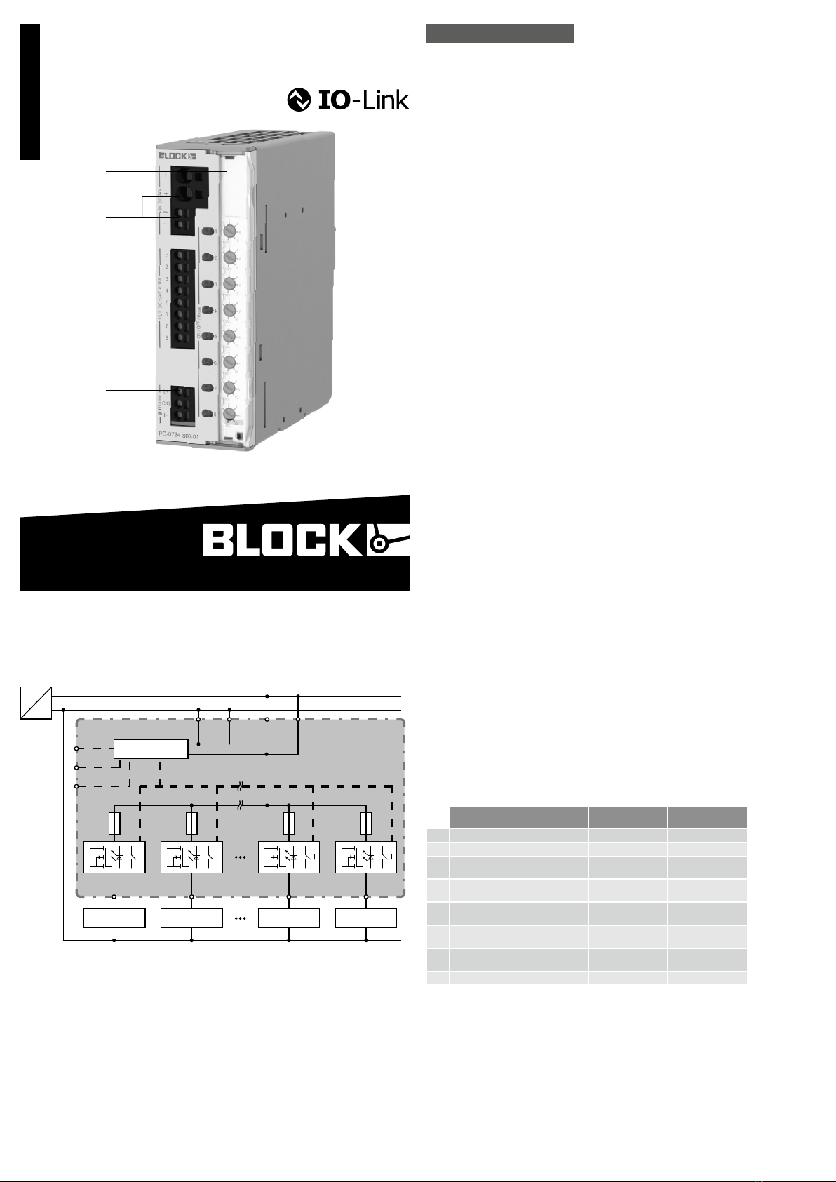
Sealed cover of the current-select or-switches
DC input (+24 V and 0 V)
The 0 V connection of the device merely serves to supply the internal electronic
circuits.
Outputs for connecting the load circuits. The 0 V of the loads must be supplied
directly to the power supply by means of separate lines.
Current-selector-switches
Pushbut tons On/O ff/Reset with integrat ed LED
IO-LINK interface
User elements
Fig. 1
1
2
3
4
5
6
Capot de protection des sélecteurs
Entrée DC (+24 V et 0 V).
La connexion du 0 V est utilisée uniquement pour l’alimentation du disjoncteur
Sorties pour le raccordement des charges. Le 0 V des charges doit être raccordé
directement à l’alimentation électrique par des câbles séparés.
Sélecteur
Bouton marche/ arrêt / réinitialisation avec LED intégrée
Interface IO-LINK
Eléments de commande
Fig. 1
Operating states,
signaling, reactions
Etats de fonctionnement,
signalisation, réactions
1) After the initialization of the device the outputs are switched on (load dependent).
2) The output is automatically deactivated in accordance with tripping-curves-characteristics.
3) The stat e is saved at po wer-off of all outputs.
4) After a specific time interval (Thermal relief) change to operational condition Z 6. If the unit is switched off
the remaining time is saved and will resume with the next switch on. This reliably prevents overloading if the
uni t is immediately switched back on.
5) The affected output can be reset by pressing the push button twice or through an impulse over the IO-LINK
interface. Change to operational condition Z1.
1) Une fois le module initialisé, les sorties seront activées dépendamment de la charge.
2) La sortie est désacti vée au tomatiquement conformément à la carac téristique de déclenchement
3) L’é tat de fonc t ionnement de chaque sortie est enregistr é à la coupur e de l’appareil.
4) Apr ès un temps d‘attente (relaxation thermique), la transition vers l‘é tat de fonc t ionnement Z6 a lieu.
Lorsque l‘appareil est éteint , le temps d‘at tente restant es t mémorisé et le redémarrage est att endu .
De cet t e façon, la surcharge des éléments de commut ation est empêchée de façon fiable,
même si l‘appareil est immédia tement allumé.
5) La sor tie conc ernée peut êtr e réinitialisée en pressant 2 X sur le bouton ou via une impulsion sur l’in ter f ac e
IO-LINK, passage à l’état Z1.
State / Description LED Pushbutton pressed
=> go to...
Z 0 Initialization 1) off ---
Z 1 Output on, function OK green Z 4
Z 2 Output current > 90 % of rated current green
flashing
Z 4
Z 3 Output current > rated current 2) green flashing Z 4
Z 4 Output was switched off manually or via
interface 3)
red Z 1
Z 5 Output was switched off automatically (over
current), thermal relaxation active 4)
red
flashing
---
Z 6 Output was switched off automatically (over
current), thermal relaxation finished
orange flashing Z 4
Z 7 Output malfunction (internal fuse blown) red flasing fast Z 4
Etat de fonctionnement / Description LED Bouton est actionné=>
aller à...
Z 0 Initialisation de module 1) arrêt ---
Z 1 Sortie est commutée, Fonction OK vert Z 4
Z 2 Corrient e de salida > 90 % de la Courant nominal clignote vert Z 4
Z 3 Courant de sortie > Courant nominal 2) clignote vert Z 4
Z 4 La sortie est déactivée manuellement ou par
interface 3)
rouge Z 1
Z 5
La sortie est désactivée en raison d’un courant
de surcharge,
détente thermique active 4)
clignote rouge ---
Z 6
La sor tie est désactivée en raison d’un courant
de surcharge,
la détente thermique est terminée 5)
clignote orange Z 4
Z 7 Erreur de l’appareil (fusible défectueux détecté) clignote rapidement rouge Z 4
PC-0724-800-0I1
Eingangsdaten Input data Entrée
Eingangsnennspannung Nominal input voltage
Tension nominale d’entr ée
DC 24 V
Eingangsspannungsbereich Input voltage range
Plage de tension d’entr ée
18 - 30 Vdc
Maximale Restwelligkeit/Rippel der speisenden
Eingangsspannung
Maximal residual ripple of supplied input voltage Ondulation résiduelle maximale/ondulation de la
tension d’entrée d‘alimentation 3 %
Erforderliche Eingangsspannung zum Einschalten
der Ausgänge
Required input voltage for turning on of outputs Tension d’entr ée requise pour la mise en service
des sorties 20 V
Max. Dauerstrom des Moduls Max. tot al input current Courant permanent max . du module 70 A
Max. Dauerstrom pro Klemmenpol Max. input current for each pole of terminal Courant permanent max . par pôle de borne 40 A
Überspannungsschutz
Suppressordiode
Over voltage protection
Suppressor diode
Protection contre les surtensions
Diode Transil 33 V
Ruhestrom im Leerlauf @ 24 V St and- by current @ 24 V Courant de repos à vide @ 24V 55 mA
Verlustleistung im Leerlauf @ 24 V Power losses in stand-by mode @ 24 V Pertes en puissance à vide @ 24V 1,32 W
Anschlüsse Eingang Terminals input Raccordement entrée Push- In, max 6 mm² (2 x „+“)
Push- In, max 2,5 mm² (2 x „-“)
Ausgangsdaten Output data Sortie
Ausgangsnennspannung Nominal output voltage Tension nominale de sortie DC 24 V
Ausgangsnennströme
einstellbar
Nominal output current
adjustable
Courants nominaux réglable de sortie 8 x (1, 2, 4, 6, 10 A) /
8 x (1, 2, 3, 4, 6, 8, 10 A) via IO-LINK
Maximaler Spannungsabfall zwischen Ein- und Ausgang
Maximum voltage drop bet w een input and output Chute de tension ma ximale entre entrée et sortie 200 mV @ 8 x 10 A
Modulinitialisierungszeit Initialization time Temps d’initialisation de module 250 ms
Zuschaltverzögerung der Kanäle
lastabhängig
Turn-on delay of outputs
load dependent
Retard d’activation des canaux
selon la charge min. 50 ms / max. 5 s
Wartezeit nach Abschaltung eines Ausgangs
(Thermische Entspannung)
Kur zschluss (A ) ... Über last (B)
Waiting periode a f ter swi tch - of f of an out pu t
(thermal relaxation)
short circuit (A ) ... overload (B)
Temps d’attente aprè s mise hors service d’une
sortie (détente thermique)
cour t-circuit ( A ) ... surcharge (B)
500 ms ( A ) … 20 s (B)
Maximale Verlustleistung Maximum power losses Pertes en puissance maximales 20 W @ 8 x 10 A
Wirkungsgrad Efficiency Rendement 99 %
Maximale Lastkapazit ät pro Ausgang Ma ximum t urn- on capacit y for each output Charge capacitive maximale par sortie > 50 … 500 mF
Integrierte Ausgangssicherungen pro Ausgang Int ernal output fuse for each output Fusibles de sor tie interne par sortie 15 A
Rückspeisefestigkeit Resistance t o reverse fee d ma x . Tension de retour max. 35 V
Parallelschaltung von Ausgängen Par allel use of ou tputs Mon tage en parallèle de sor ties -
Serienschaltung von Ausgängen Serial use of outputs Montage en série de sor ties -
Anschlüsse Ausgänge Terminals outputs Raccordement sorties Push-In, ma x 2,5 mm² (8 x „+“)
Signalisierung Signaling Signalisation
Statusanzeige (pro Ausgang)
LED (ro t, gr ün, or ange)
Status display (for each output)
LED (red, green , orange)
Indication du statut (par sortie)
LED (rouge, ver te, orange ) o
Schnittstelle Interface Interface
IO-LINK V1.1
COM3 230kB
IO-LINK V1.1
COM3 230kB
IO-LINK V1.1
COM3 230kB
o
IO-LINK L + (BN) IO-LINK L + (BN) IO-LINK L + (BN) DC / + 24 V
IO-LINK C/Q (BK ) IO-LINK C/Q (BK ) IO-LINK C/Q (BK ) Communication
IO-LINK L - (BU) IO-LINK L - (BU) IO-LINK L - (BU) DC / 0 V
Anschlüsse Schittstelle Terminals interface Raccordement interface Push-In, max 2,5 mm² (L+, C/Q , L-)
Umwelt Environment
Environnement
Lagertemperatur Storage temperature Température de stockage -25 °C ... +85 °C
Umgebungstemperatur Operational temperature Température ambiante -25 °C ... +70 °C
Derating Derating Derating max. output curr ent per channel: 10 A
total current (all channels togehther):
max. 50 A @ 60 °C
max. 40 A @ 70 °C
Konvektionskühlung Convection cooling Refroidissement par convection o
Luftfeuchtigkeit, keine Betauung Humidity, no condensation Humidi té de l’air , absenc e de condensation 5 … 96 %
Einsatz in Bereichen mit Verschmutzungsgrad 2 For installation in Pollution Degree 2 environment
Pour installation dans un environnement de pollution 2
o
Zum Anschluss Kupf erkabel mit min. 75° C ver -
wenden
Use Copper Conduc tor s only, rat ed 75° C
Utiliser uniquement des câbles de connexion en cuiv re
supportant des plages de températ ur es 75 °C
o
Erforderlicher Mindestabstand (seitlich) Required minimum spacing (left/right) Distance minimale requise (latérale) -
Erforderlicher Mindestabstand (oben/unten) Required minimum spacing (over/under) Distance minimale requise (en haut /en bas) 40 mm
Allgemeine Daten General data Données générales
Schutzart nach IEC 60529 Degree of pr otec tion ac c. t o IEC 60529 Type de pr ote ction selon EN 60529 IP 20
Schutzklasse nach EN 61140 Protection class acc. t o EN 61140 Classe de pro tec t ion selon EN 61140 III
Normen Safety standards Normes
Sicherheit Safety Sécurité EN 60950-1, EN 50178, EN/ IEC 60204-1
EMV EMC CEM EN 61000-6-2, EN 61000-6-3
Schutzkleinspannung (SELV/PELV) Safet y extra- low voltage (SELV/PELV) Trè s basse tension de sécurité ( TBTS / TBTP ) IEC 60364-4- 41 (DIN VDE 0100-410)
CE gemäß 2014/30/EU (EMV-Richtlinie) CE acc. t o 2014/30/EU (EMC-Directive ) Conforme à la direc tive 2014/30/EU (CEM) o
Prüfzeichen
Markings Approbation
UL 2367 UL 2367 UL 2367 Special-purpose Solid-state overcurrent
protectors, Component Recognition;
UL cat egor y QVRQ2, E-File: E356250
UL 508 UL 508 UL 508 List ed for the use as Indus trial Cont rol Equip-
ment; U. S.A . (UL 508) and Canada
(C22.2 No. 14-10), E-File: E219022
Mechanische Daten Measures and weights
Caract
éristiques mécaniques
Be festigung auf Normprofilsc hiene DIN EN 60715 -
TH35-15/7,5
Mount ing on standard rail DIN EN 60715-TH35-
15 / 7, 5
Mon tage sur rail DIN EN 60715-TH35-15/7,5
o
Gewicht Weight Poids 0,4 kg
Maße (B x H x T)
Tiefe ab Oberkant e TH35
Dimensions (W x H x D)
depth without TH35
Dimensions (L x H x P)
profondeur sans TH35 42 x 127 x 116,5 mm
Bestellnummern Order numbers Référence produit PC-0724-800-0I1
Données techniquesTechnical dataTechnische Daten
T
Hinweis:
Eine detaillierte Beschreibung finden Sie im
Handbuch des Schutzschalters, das auf der
Produktseite unter www.block.eu kostenlos
zum Download bereitsteht.
Notice:
You can download the complete manual with
detailed description from our product site
under www.block.eu
Indication:
Vous trouverez une description détaillée
dans le manuel du disjoncteur de protection
que vous pouvez télécharger gratuitement
sur la pag e pr oduit à l’adr es se
www.block.eu.
deutsch english
Der elektronische Schutzschalter ist mit
einer IO-LINK Schnittstelle ausgestattet.
Über die IO-LINK Schnittstelle lassen sich
sowohl betriebsrelevante Informationen
aus dem Schutzschalter digital auslesen
als auch gezielt einzelne Ausgangskanäle
ein- oder ausschalten, sowie der Auslö-
sestrom eines jeden Ausgangs individuell
einstellen (Stromwahlschalter in Schalter-
stellung „RC“). Ein Reset der ausgelösten
Kanäle ist ebenfalls über die Schnittstelle
möglich.
Die Anbindung an eine Steuerung erfolgt
über einen IO- LINK Mast er.
Der IO-LINK Master muss den IO-LINK
Standard V1.1 erfüllen und den COM3
Mode unterstützen.
The electronic circuit breaker is equipped
with an IO-LINK int er face.
Via the IO-LINK int erface it is possible to
read out all the information of the circuit
breaker as well as to turn channels on/off
or reset tripped channels and select the
individual tripping current for each output
(current-selector-switch in position
„RC“).
The connection to the PLC is done by an
IO-Link Master.
The IO-LINK Master has to support the
IO-LINK specification V1.1 and at least
COM3.
Le disjoncteur de protection électronique
est équipé d’un interface IO-LINK.
L’interface IO-LINK permet de lire des
informations pertinentes concernant le
fonctionnement provenant du disjoncteur
de prot ection ainsi que d’activer ou dé-
sactiver de voies de sortie individuelles de
manière ciblée et aussi de sélectionner le
courant de déclenchement pour chaque
sortie individuellement (sélecteur de cou-
rant en position „RC“). Un réarmement de
toutes les sorties disjonctées est aussi
possible à travers l’inter face IO-LINK.
La connexion à une ligne de commande
peut être effectué à travers le maître
IO-LINK.
Le maître IO-LINK doit remplir le IO-LINK
Standard V1.1 et doit sout enir le COM3
Mode.
IO-LINK Schnittstelle IO-LINK interface Interface IO-LINK
Mounting
Fig. 4a
AUF TRAGSCHIENE AUFRASTEN
I) Gerätevorderseite leicht nach oben
drehen
II) Auf Hutschiene aufsetzen
III) Bis zum Anschlag nach unten
schieben
IV) Unten gegen die Befestigungsebene
drücken (klick)
V) Leicht am Gerät rütteln, um Verrie-
gelung zu prüfen
Fig. 4b
DEMONTAGE VON TRAGSCHIENE
I) Verriegelungslasche mit Schrauben-
dreher nach unten ziehen und öf fnen.
II) Gerät aus Tragschiene aushängen.
Montage
Fig. 4a
SNAP ON SUPPORT RAIL
I) Tilt the unit slightly rearwards
II) Fit the unit over top hat rail
III) Slide it downward until it hits the stop
IV) Press against the bottom front side
for locking (click)
V) Shake the unit slightly to check the
locking action
Fig. 4b
REMOVAL FROM DIN RAIL
I) Locking tab with a screwdriver and
pull down to open.
II) Unhook the device from DIN rail.
Fig. 4a
I
II
III
IV
V
Fig. 4b
II
I
Montage
Fig. 4a
POUR FIXER LE MODULE SUR LE RAIL
I) Pencher légèrement le module vers
l’arrière
II) Placer le module sur le bord supérieur
du rail.
III) Encliqueter le module vers le bas
jusqu’à l’arrêt.
IV) Afin de verrouiller le module, pousser
sur la par tie inférieure (clic)
V) Vérifier l’enclenchement en secouant
légerement le module.
Fig. 4b
DEMONTAGE DU RAIL
I) Tirer le dispositif de verrouillage à
l’aide d’un tournevis vers le bas pour
ouvrir.
II) Décrocher l’appareil du rail DIN.
Sicherungskennlinie
Tripping characteristic
Caractéristique du disjoncteur
Ausgangsstrom (A)
Output current (A)
Courant de sortie (A)
ü
Auslösezeit (ms)
Tripping time (ms)
Temps de déclenchement (ms)
ü
PC-0724-800-0I1
Technische Änderungen vorbehalten.
Subject to change.
Sous réserve de modifications techniques.
1 10
10
100
1000
10000
100000
100
2 A 3 A 4 A 6 A
1 A
8 A
10 A
block.eu
BLOCK Transformatoren-Elektronik GmbH
Max-Planck-Straße 36-46 . 27283 Verden, Germany
[email protected] . block.eu

Other Block Circuit Breaker manuals

Block PM-0748-200-0 User manual

Block

Block PM-0748-200-0 User manual

Block ECONOMY SMART User manual

Block

Block ECONOMY SMART User manual

Block ECONOMY SMART User manual

Block

Block ECONOMY SMART User manual

Block ECONOMY SMART User manual

Block

Block ECONOMY SMART User manual

Popular Circuit Breaker manuals by other brands

Siemens TC1J6600 installation instructions

Siemens

Siemens TC1J6600 installation instructions

Siemens GM-SG instruction manual

Siemens

Siemens GM-SG instruction manual

Eaton CH Instructional Leaflet

Eaton

Eaton CH Instructional Leaflet

IEK VA47-100 Operation manual

IEK

IEK VA47-100 Operation manual

ABB SACE Tmax XT5 Operation and maintenance manual

ABB

ABB SACE Tmax XT5 Operation and maintenance manual

Siemens 5SL5 RC Series operating instructions

Siemens

Siemens 5SL5 RC Series operating instructions

ABB XT7M manual

ABB

ABB XT7M manual

Eaton NZM3-XR Series Instruction leaflet

Eaton

Eaton NZM3-XR Series Instruction leaflet

TAVRIDA ELECTRIC VCB15 Product guide

TAVRIDA ELECTRIC

TAVRIDA ELECTRIC VCB15 Product guide

Westinghouse F-122 Instruction book

Westinghouse

Westinghouse F-122 Instruction book

Doepke DFS 4 B SK series Installation and operating manual

Doepke

Doepke DFS 4 B SK series Installation and operating manual

Toshiba VK Series instructions

Toshiba

Toshiba VK Series instructions

ABB SACE Emax 2 E2.2 Installation, operation and maintenance instructions for the installer and the user

ABB

ABB SACE Emax 2 E2.2 Installation, operation and maintenance instructions for the installer and the user

Siemens SION 3AE-Z M30 Service & Maintenance

Siemens

Siemens SION 3AE-Z M30 Service & Maintenance

Eaton QSA63N1 Series Instruction leaflet

Eaton

Eaton QSA63N1 Series Instruction leaflet

Siemens JG installation instructions

Siemens

Siemens JG installation instructions

Siemens 3WX3647-5JE00 operating instructions

Siemens

Siemens 3WX3647-5JE00 operating instructions

Eaton NZMB Series Instruction leaflet

Eaton

Eaton NZMB Series Instruction leaflet

manuals.online logo
manuals.online logoBrands
  • About & Mission
  • Contact us
  • Privacy Policy
  • Terms and Conditions

Copyright 2025 Manuals.Online. All Rights Reserved.