Blodgett Combi COS-8E Owner's manual
COSĆ8E, COSĆ8EDS, BCSĆ8E
BCSĆ8DS AND CNVĆ8E
ELECTRIC COOKING APPLIANCES
INSTALLATION - OPERATION - MAINTENANCE
COSĆ8E, COSĆ8EDS, BCSĆ8E
BCSĆ8DS ET CNVĆ8E
APPAREILS DE CUISSON D'ÉLECTRIQUE
MANUEL D'INSTALLATION - FONCTIONNEMENT - ENTRETIEN
BLODGETT COMBI
www.blodgett.com
44 Lakeside Avenue, Burlington, Vermont 05401 U A Telephone: (802) 658Ć6600 Fax: (802)864Ć0183
PN R8132 Rev D (6/01)
E 2000 - Blodgett Combi

A PERSONAL WORD FROM BLODGETT COMBI
QUELQUES MOTS DE BLODGETT COMBI
Congratulations on your purchase of a BLODGETT Combi appliance. We
firmly believe that your choice has been a wise one, and trust you will reĆ
ceive many years of excellent service from your new Combi.
You will find that cooking with Combi appliances saves time, labor and
extensive cleaning of both the kitchen and the unit.
With Combi appliances the quality, taste, consistency, and look of your
food are improved, thus endorsing the policy to which we've always adĆ
hered: For Better Cooking!"
Once you've had a chance to use your Combi, please tell us, your dealer
and colleagues about any creative and interesting applications you have
discovered; exchange ideas with other users. Be sure to advise us or
your dealer immediately should any mechanical or technical problems
be encountered (...we're here to help!) and above all Enjoy Cooking the
BLODGETT Combi Way!
For information on cooking, please refer to our separate cooking guide.
Toutes nos félicitations sur votre achat d'appareil de Blodgett Combi.
Nous croyons fermement que votre choix est un choix raisonnable et
nous sommes certains que vous obtiendrez de nombreuses années
d'excellent service de votre nouveau four multiĆusages.
Vous allez découvrir que la cuisson dans les appareils Combi économise
le temps, le travail et le degré de nettoyage de l'appareil aussi bien que
de la cuisine.
Avec les appareil de Combi, la qualité, le goût, la consistence et l'apparĆ
ence des aliments sont améliorés, s'accordant, de ce fait, avec notre
politique "Pour une meilleure cuisson !"
Une fois que vous aurez eu la chance d'utiliser notre Combi, informez
nous, votre concessionnaire et vos collègues, de toutes les applications
nouvelles et intéressantes que vous avez découvertes ; échangez vos
idées avec d'autres utilisateurs. N'hésitez pas à nous prévenir, ou votre
concessionnaire, de tout problème mécanique ou technique que vous
pourriez rencontrer (... nous sommes ici pour vous aider) et parĆdessus
tout RégalezĆvous à cuisiner à la façon BLODGETT Combi!
Pour obtenir de plus amples informations sur l'art culinaire, veuillez conĆ
sulter notre livre de cuisine séparé.

IMPORTANT
FOR YOUR SAFETY
Do ot store or use gasoli e or other flammable vapors or liquids i the vici ity
of this or a y other applia ce.
AVERTISSEMENT
Ne pas e treposer i utiliser de l'esse ce i d'autres vapeurs ou liquides i flamĆ
mables da s le voisi age de cet appariel, i de tout autre appareil.
WARNING: IMPROPER INSTALLATION, ADJUSTMENT, ALTERATION, SERVICE OR
MAINTENANCE CAN CAUSE PROPERTY DAMAGE, INJURY OR DEATH. READ THE
INSTALLATION, OPERATING AND MAINTENANCE INSTRUCTIONS THOROUGHLY
BEFORE INSTALLING OR SERVICING THIS EQUIPMENT
AVERTISSEMENT: UNE INSTALLATION, UN AJUSTEMENT, UNE ALTÉRATION, UN
SERVICE OU UN ENTRETIEN NON CONFORME AUX NORMES PEUT CAUSER DES
DOMMAGES À LA PROPRIÉTE, DES BLESSURES OU LA MORT. LISEZ ATTENTIVEĆ
MENT LES DIRECTIVES D'INSTALLATION, D'OPÉRATION ET D'ENTRETIEN AVANT
DE FAIRE L'INSTALLATION OU L'ENTRETIEN DE CET ÉQUIPEMENT.
The i formatio co tai ed i this ma ual is importa t for the proper i stallatio ,
use, a d mai te a ce of this ove . Adhere ce to these procedures a d i strucĆ
tio s will result i satisfactory baki g results a d lo g, trouble free service.
Please read this ma ual carefully a d retai it for future refere ce.
Les i formatio s do ées da s le prése t ma uel so t importa tes pour i staller,
utiliser et e trete ir correcteme t ce four. Le respect de ces i structio s et procéĆ
dures permettra d'obte ir de bo s résultats de cuisso et u e lo gue durée de serĆ
vice sa s problèmes. Veuillez lire le prése t ma uel et le co server pour pouvoir
vous y reporter à l'ave ir.
Errors: Descriptive, typographic or pictorial errors are subject to correctio . SpecificaĆ
tio s are subject to cha ge without otice.
Erreurs:Les erreurs de descriptio , de typographie ou d'illustratio fo t l'objet de
correctio s. Les caractéristiques so t sujettes à modificatio s sa s préavis.

Your ervice Agency's Address:
Adresse de votre agence de service:
Model/Modèl:
erial Number/Numéro de série:
Your oven was installed by/
Installateur de votre four:
Your oven's installation was checked by/
Contrôleur de l'installation de votre four:

Table of Co te ts/Table des Matières
I troductio
The Blodgett Combi Cooking Line 2. . . . . .
Description of the Blodgett Combi
Cooking Line 3. . . . . . . . . . . . . . . . . . . . . . . . .
Oven Features 4. . . . . . . . . . . . . . . . . . . . . . .
I stallatio
Owner's Responsibilities 5. . . . . . . . . . . . . . .
Location 6. . . . . . . . . . . . . . . . . . . . . . . . . . . . .
Agency Approvals 7. . . . . . . . . . . . . . . . . . . .
Utility Connections 8. . . . . . . . . . . . . . . . . . . .
Optional Leg Attachment 10. . . . . . . . . . . . . .
tacking 11. . . . . . . . . . . . . . . . . . . . . . . . . . . . .
Final Check and Adjustments 12. . . . . . . . . .
Final Check Lists 13. . . . . . . . . . . . . . . . . . . . .
Operatio
Oven tartĆUp 14. . . . . . . . . . . . . . . . . . . . . . . .
CombiĆOven/ teamer tandard Controls 15
Optional CombiĆOven/ teamer
Cook & Hold 17. . . . . . . . . . . . . . . . . . . . . . . . .
Convection teamer tandard Controls 20.
Convection Oven tandard Controls 21. . . .
Optional Convection Oven
Cook and Hold 22. . . . . . . . . . . . . . . . . . . . . . .
Optional Meat Probe 25. . . . . . . . . . . . . . . . . .
Mai te a ce
pray Bottle Operating Procedure 26. . . . . .
Cleaning and Preventive Maintenance 27. . .
Decalcification 28. . . . . . . . . . . . . . . . . . . . . . .
I troductio
La ligne d'appareils de cuisson de Blodgett
Combi 30. . . . . . . . . . . . . . . . . . . . . . . . . . . . . . .
Description de la ligne d'appareils de
cuisson de Blodgett Combi 32. . . . . . . . . . . .
Caractéristiques 33. . . . . . . . . . . . . . . . . . . . . .
I stallatio
Responsabilités du propriétaire 34. . . . . . . . .
Placement 35. . . . . . . . . . . . . . . . . . . . . . . . . . .
Normes et Codes 36. . . . . . . . . . . . . . . . . . . . .
Branchement Utilitaires 37. . . . . . . . . . . . . . . .
Fixation des pieds en Option 39. . . . . . . . . . .
uperposition Ć Assemblage
section double 40. . . . . . . . . . . . . . . . . . . . . . .
Vérification finale et derniers réglages 41. . .
Vérifications Finales 42. . . . . . . . . . . . . . . . . . .
Utilisatio
Mise en Marche du Four 43. . . . . . . . . . . . . . .
CombiĆFour/étuve à Vapeur Contrôles
tandards 44. . . . . . . . . . . . . . . . . . . . . . . . . . .
CombiĆFour/étuve à Vapeur Cuisson et
Pause en Option 46. . . . . . . . . . . . . . . . . . . . . .
CombiĆConvection/étuve à Vapeur
Contrôles tandards 50. . . . . . . . . . . . . . . . . .
CombiĆFour à Convection Contrôles
tandards 51. . . . . . . . . . . . . . . . . . . . . . . . . . .
CombiĆFour à Convection Cuisson et
Pause en Option 52. . . . . . . . . . . . . . . . . . . . . .
onde à Viande en Option 56. . . . . . . . . . . . .
E tretie
Procédé de fonctionnement de la
bouteille vaporisatrice 57. . . . . . . . . . . . . . . . .
Entretien Préventif et Nettoyage 58. . . . . . . .
Détartrage 59. . . . . . . . . . . . . . . . . . . . . . . . . . .

I troductio
2
The Blodgett Combi Cooki g Li e
For quite some time, commercial cooking equipĆ
ment has remained more or less unchanged.
There are kettles, deck ovens, the good old range
with its legion of pots āand āmany āother āextra
āappliances. The result: time expenditure, excesĆ
sive manual work, and countless cleaning proĆ
cesses. The last āāāfew āāāyears āāhave āāpaved āāthe āāway āāfor
āa revolution in the equipment of restaurant and inĆ
stitutional kitchens. Blodgett Combi is proud to ofĆ
fer three different cooking platforms, one of which
is sure to match your needs. The Blodgett Combi
line includes:
DThe Blodgett Combi Co vectio Steamer
DThe Blodgett Combi Co vectio Ove
DThe Blodgett CombiĆOve /Steamer
All Blodgett Combi appliances improve your kitchĆ
en through:
Dincreased productivity
Da wider range of menu choices
Da simplified cleaning process
The work process is simplified since products are
prepared on or in steam table āpans āand trays.
Food can be cooked, stored, and transported with
āthe āsame āāpans. ā mall āamounts of product can be
processed efficiently; preĆcooked and conveĆ
nience foods can be reheated within minutes.
COMBI CONVECTION STEAMER
teaming is a well known cooking process freĆ
quently used in restaurant and institutional kitchĆ
ens. With the Combi Convection teamer, it is now
possible to enjoy the many advantages of steamĆ
ing including shorter cook times, higher product
quality and vitamin retention.
The Combi Convection teamer is offered in two
models, each with different steam producing sysĆ
tems.
DThe BC Ć8E model includes a built in steam
generator. This unit includes an inlet, funnel asĆ
sembly and valve lever for decalcification.
DThe BC Ć8D is a direct steam unit that is conĆ
nected to an external steam source.
COMBI CONVECTION OVEN
Cooking in the Combi Convection Oven differs
from cooking in a traditional deck or range oven
since heated air is constantly recirculated over the
product by a fan in an enclosed chamber. The
moving air continually strips away the layer of cool
air surrounding the product, quickly allowing the
heat to penetrate. The result is a high quality prodĆ
uct, cooked at a lower temperature in a shorter
amount of time.
COMBIĆOVEN/STEAMER
With the Oven/ teamer you have the choice of two
cooking processes: team and Hot Air, either...
Deparately
DCombined, or
DIn equence using two or three functions during
one cooking process. We call this combiĆsteamĆ
ing and combiĆbaking.
For easy operation you can choose from three
modes:
team Hot Air Combi
team &
Hot Air
In the team mode you can:
DĂsteam DĂblanch DĂpoach
DĂdefrost DĂrethermalize
In the Hot Air mode you can
DĂroast DĂbake DĂbraise
In the Combi mode you can:
DĂdefrost DĂroast DĂrethermalize
DĂreheat DĂbake DĂsous vide*
DĂproof* DĂcook & hold*
* with optional digital controls
The CombiĆOven/ teamer is offered in two models,
each with different steam producing systems.
DThe CO Ć8E model includes a built in steam
generator. This unit includes an inlet, funnel asĆ
sembly and valve lever for decalcification.
DThe CO Ć8ED is a direct steam unit that is conĆ
nected to an external steam source.

I troductio
3
Descriptio of the Blodgett Combi Cooki g Li e
ABOUT THE COMBI LINE
Blodgett Combi appliances are quality produced
using highĆgrade stainless steel with first class
workmanship.
The use of high quality insulation impedes excesĆ
sive heat radiation and saves energy.
Optional adjustable legs adapt easily to slightly
uneven surfaces. Optional floor stands have been
designed for use with all of the table models.
Ove /Steamers a d Co vectio Steamers
The high performance steam control system
makes it possible to enjoy all of the advantages of
a high quality steamer at the flick of a switch. Fresh
steam enters the oven cavity without pressure and
is circulated at high speed. This process enables
quick and gentle cooking and ensures high quality
product while providing convenient working methĆ
ods.
A patented quench system keeps the air in the unit
clean. Fumes are extracted from the appliance,
quenched, and directed out through the condensĆ
er drain. The exhaust system is effective in all
cooking modes and results in better quality foods
and o flavor tra sfer. The fan, which is guarded
against accidental finger contact, is driven by a
quiet and powerful motor. The condenser draws
out excess steam from the appliance. CondensaĆ
tion and waste water, which result during steamĆ
ing and cleaning, are continuously drained.
OPERATION
The practical oven door, with a viewing window,
has a wide swing radius and handle which can be
operated easily, even with wet or greasy hands.
Ease of operation is guaranteed through the simĆ
ple arrangement of the controls. Graphic symbols
make the appliances easy for even inexperienced
kitchen staff to operate. All modes can be selected
with one switch. This includes the Cool Down
mode, which allows the oven cavity to cool down
rapidly with the door opened or closed.
Cleaning is kept to a minimum. The interior can be
sprayed with a cleaning solution to easily remove
crusts and stains. The oven is designed for easy
care and is welded water tight so that the internal
cooking cavity may be rinsed with a hose after the
cleaning process.

I troductio
4
Ove Features
tandard Features
14
2
3
6
7
5
3
8
COSĆ8E Shown
9
Figure 1
1 Control Panel
2 Oven Door
3 DripĂCollectorĂ(self draining)
4 Door Handle
5 VentĂ(not shown)
6 Decalcifying Inlet & Funnel Assembly*
7 Decalcifying Valve Lever*
8 Fuses, Power upply
9 Tilt Down Panel crew
* only on COSĆ8E and BCSĆ8E
I stallatio
5
Ow er's Respo sibilities
1. Oven(s) are uncrated, stacked (if applies) and
put in place.
NOTE: Refer to eg Attachment and Stacking
information provided.
2. The owner/operator must have the following
plumbing and electrical requirements met and
installed.
NOTE: Refer to the Utility Connection inforĆ
mation provided.
WARNING!!
Improper i stallatio , adjustme t, alterĆ
atio service or mai te a ce ca cause
property damage, i jury or death. Read
the i stallatio , operatio a d mai teĆ
a ce i structio thoroughly before i Ć
stalli g or servici g this equipme t.
PLUMBING
Water
Building Water Pressure (min/max) 40 P I min/50 P I max
Cold Water Connection 3/4" Hose Fitting, 3/8" ID hose minimum
Hot Water Connection* 3/4" Hose Fitting*, 3/8" ID hose minimum
Pressure Regulator etting 35 P I Preset
Drai age Atmospheric Vented Drain
Drain Connection 2" Copper
Avg Water Drain Temp. 122_F (50_C)
ELECTRICAL
Electrical* 18.4kw
Amp/Li e (max)
Volt 3 Phase 1 Phase
208 52 89
240 45 77
480 23 N/A
By Mode Steam 18.5kw
y
Hot Air 18.5kw
Combi 18.5kw
Blower Motor .5 hp / 0.5 kw
*Not applicable with COSĆ8EDS, BCSĆ8DS and CNVĆ8E

I stallatio
6
Locatio
The well planned and proper placement of your
appliance will result in long term operator conveĆ
nience and satisfactory performance.
The following clearances must be maintained beĆ
tween the unit and any combustible or nonĆcomĆ
bustible construction.
DOven body right side - 4" (10 cm)
DOven body left side - 4" (10 cm) with casters
12" (30 cm) without
casters
DOven body back - 4" (10 cm)
NOTE: For models with hose assemblies on the
back of the unit, the hose must be 4" (10
cm) from the wall.
If optional casters are not used, the following
clearances are recommended for service.
DOven body left side - 12" (30 cm)
DOven body back - 12" (30 cm)
Place the unit in an area which is free of drafts and
accessible for proper operation and servicing.
Keep the oven area free and clear of all combusĆ
tibles such as paper, cardboard, and flammable
liquids and solvents.
DO NOT place the oven on a curb base or seal to
the wall; either condition will prevent proper ventiĆ
lation to the blower motors. light unevenness can
be corrected with the adjustable legs.
Heat sources must not be located near the air
vents on the left hand side of the unit. Consult the
factory for an optional protective side heat shield
kit if a warm surface or water source is to the left
of the unit. If excessive ambient temperature or a
water source is present a heat shield must be addĆ
ed to the left hand side of the oven to protect the
unit from excessive heat or water
DCO Ć8E heat shield P/N R9048
DCO Ć8ED heat shield P/N R9048
DBC Ć8E heat shield P/N R9048
DBC Ć8D heat sheild P/N R9048
DCNVĆ8E heat shield P/N R9048
On all models, tripping the blower motor's thermal
overload device indicates an excessive ambient
temperature at the side of the oven. This must be
corrected to prevent permanent damage to the
oven. All motor bearings are permanently lubriĆ
cated by the manufacturer; there is no need for
additional lubrication during the operational lifeĆ
time of the motors.
I stallatio
7
Age cy Approvals
THE IN TALLATION IN TRUCTION CONĆ
TAINED HEREIN ARE FOR THE U E OF QUALIĆ
FIED IN TALLATION AND ERVICE PER ONNEL
ONLY. IN TALLATION OR ERVICE BY OTHER
THAN QUALIFIED PER ONNEL MAY RE ULT IN
DAMAGE TO THE OVEN AND/OR INJURY TO
THE OPERATOR.
Qualified installation personnel are individuals, a
firm, a corporation, or a company which either in
person or through a representative are engaged
in, and are responsible for:
DThe installation of electrical wiring from the elecĆ
tric meter, main control box or service outlet to
the electric appliance.
Qualified installation personnel must be experiĆ
enced in such work, be familiar with all precauĆ
tions required and have complied with all requireĆ
ments of state or local authorities having
jurisdiction.
U.S. a d Ca adia I stallatio s
Reference: National Electrical Code, ANSI/NFPA
70- atest Edition and/or Canadian Electrical
Code CSA C22.1 as applicable.
This equipment is to be installed in compliance
with the Basic Plumbing Code of the Building OffiĆ
cials and Code Administrators International Inc.
(BOCA) and the Food Service Sanitation Manual of
the Food and Drug Administration (FDA).
Ge eral Export I stallatio s
Installation must conform with Local and National
installation standards. Local installation codes
and/or requirements may vary. If you have any
questions regarding the proper installation and/or
operation of your unit, please contact your local
distributor. If you do not have a local distributor,
please call Blodgett Combi at 0011Ć802Ć860Ć3700.
I stallatio
8
Utility Co ectio s
HOT AND COLD WATER CONNECTION
NOTE: Hot water maximizes steam production,
but is not required. Cold water may be supĆ
plied to both inlets if hot water is not availĆ
able. Hot water must not be applied to the
cold water inlet.
COSĆ8E a d BCSĆ8E - Connect cold water hose
to the cold water (left) solenoid and hot water to
the hot water (right) solenoid. Use pressure hose
with 3/4" (1.9 cm) fittings and wall shut off valves
for service.
COSĆ8EDS, BCSĆ8DS a d CNVĆ8E - Connect
the units to quality cold water via a pressure hose
with 3/4" (1.9 cm) couplings.
1/2" Appliance Hose
With 3/4" Hose Fittings
Figure 2
Water must meet the following minimum requireĆ
ments:
DTotal Dissolved olids (TD ) content will not exĆ
ceed 30 parts per million.
DWater PH must be 7.0 or higher
WARNING!!
The use of poor quality water will i valiĆ
date your warra ty.
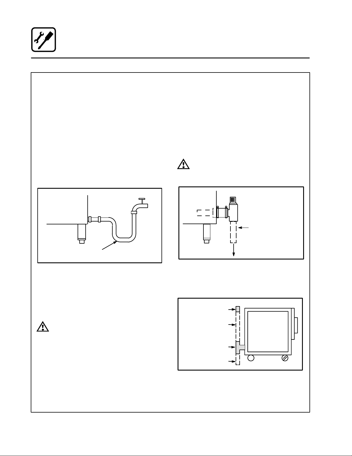
DRAIN CONNECTION
NOTE: Not applicable for CNVĆ8E convection oven.
A 2" (5 cm) copper pipe with standard drain pitch,
must be run to an open drain or connected to a
standpipe equipped with a vent.
NOTE: The waste water can also be directed to a
nearby floor drain. Flexible hose which alĆ
lows trapped water to accumulate in
sagged runs must be avoided.
WARNING!!
Failure to i stall the drai kit provided will
i validate your warra ty.
2" (5 cm) Drain
(Customer upplied)
To Drain
Figure 3
A 24" (61 cm) long standpipe must be connected
to the DWV. This allows the escaping water vapor
to exit above the inlet louvers on the back panel.
Breather Vent
Plumber Installed
Connection
Tee, Hose and Clamps
Plumber Installed
Connection To Drain
Figure 4
I stallatio
9
Utility Co ectio s
STEAM CONNECTION
NOTE: COSĆ8EDS and BCSĆ8DS only.
Connect the appliance to a 200 psi maximum exĆ
ternal steam source per local or state codes. The
steam must be clean, potable and fit for human
consumption. Failure to connect this appliance to
a suitable steam source will revoke the approval of
N F.
The appliance is equipped with an internal steam
pressure regulator set at 2 psi. Verify the regulator
is set to 2 psi prior to operating the appliance.
ELECTRICAL CONNECTION
Before making any electrical connections to these
units, check that the power supply is adequate for
the voltage, amperage, and phase requirements
stated on the rating name plate mounted on the
unit.
Wiring diagrams are located on the inside of the
louvered side panel.
NOTE: DISCONNECT THE POWER SUPP Y TO
THE UNIT BEFORE SERVICING!
U.S. a d Ca adia i stallatio
All units, when installed, must be electrically
grounded in accordance with local codes or in the
absence of local codes, with the National Electrical
Code, ANSI/NFPA 70- atest Edition and/or CanaĆ
dian Electrical Code CSA C22.1 as applicable.
Ge eral Export I stallatio s
Installation must conform with Local and National
installation standards. Local installation codes
and/or requirements may vary. If you have any
questions regarding the proper installation and/or
operation of your unit, please contact your local
distributor. If you do not have a local distributor,
please call Blodgett Combi at 0011Ć802Ć860Ć3700.
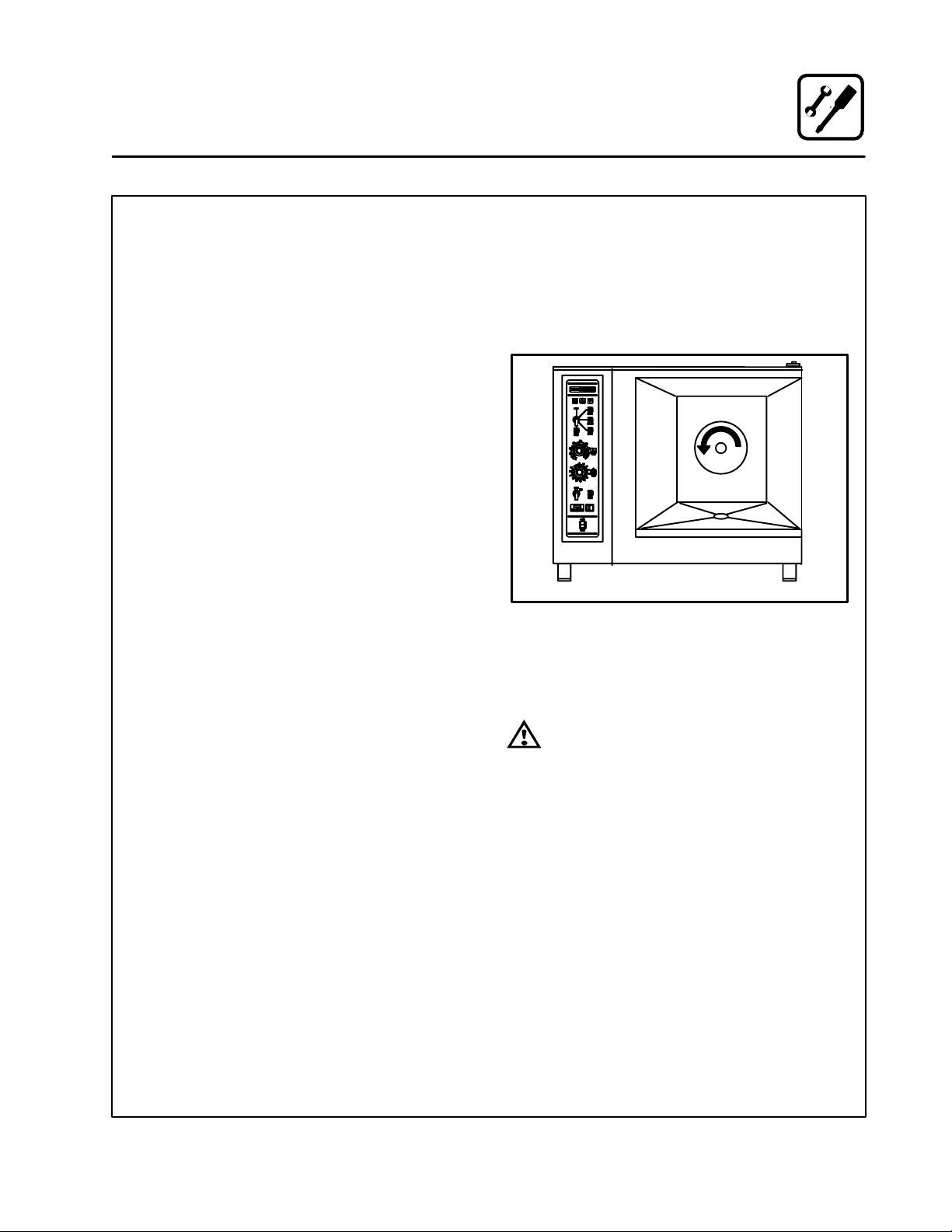
CAUTION: o 480V u its, the fa should be
checked to e sure the proper rotatio after
co ecti g the applia ce. See Figure 5. If the
fa tur s i the wro g directio , the applia ce
will ot fu ctio properly a d damage to the
u it ca occur. Improper co ectio of the apĆ
plia ce re ders the warra ty i valid.
Direction Of Fan Rotation
Figure 5
NOTE: A MANUA RESETS SHOU D BE REĆ
STORED BEFORE CONNECTING POWER
TO THE APP IANCE.
WARNING!!
Improper electrical i stallatio will i valiĆ
date your warra ty.

I stallatio
10
Optio al Leg Attachme t
LEG OPTIONS
Legs are available in 4" (10 cm), 6" (15 cm) āor ā25"
ā(64 cm) ālengths āāor āālow profile casters. The 6" legs
can be used on the lower section of a double
stacked unit. The 4" legs may be used with the opĆ
tional stands if additional height is required or
when mounting on a counter. The 25" legs are
used for a single oven located on the floor.
NOTE: For safety reasons, casters must not be
used with the 25" ā(64 cm) legs.
25I Adjustable Leg
4I Leg
6I Adjustable Leg
Low Profile Casters
Figure 6
LEG ATTACHMENT
NOTE: If low profile casters are used, install the
locking casters on the front of the oven.
The rear casters do not lock. Be sure the
locks are set on the front casters.
1. Align the threaded stud the each leg to the bolt
āholesā locatedāāā ināā ātheā āāunit'sā bottom ācorners.
Turn the legs clockwise and tighten to the
nearest full turn.
2. Align the leg plate holes with the bolt holes.
ecure with the two 1/2" bolts provided.
3. Tip the oven up on the legs. If ācastersā are
āused, checkā thatā the locksā areā setā on ātheā front
casters.
4. Except for units with casters, level the oven by
screwing the adjustable feet in or out as necĆ
essary.
6" (15 cm) egs Shown
Figure 7

I stallatio
11
Stacki g
STACKING
1. Install 6" (15 cm) legs or casters on the bottom
unit. If casters are used, the casters with
brakes must be located on the front of the
oven.
2. Remove the three screws from the top of the
bottom unit.
3. Lift and mount the upper unit onto the lower
unit. Flush the edges on all four sides. Remove
the side panel and body back of both units.
Remove the lower body back from the top
unit.
4. Bolt the upper and lower units together with
the .50Ć13 UNC bolts provided.
Rear of Units
Bolt through
holes closest
to oven center
Step 4
Remove
body back
Remove
lower body
back
Remove
louvered
panel and
save screws
Remove
body back
Step 3
Step 1
Do Not Remove
Body Top
Caster with brakes
Figure 8
PLUMBING
NOTE: When stacking a CNVĆ8E with a COSĆ8E,
COSĆ8EDS or BCSĆ8E the drains must not
be manifolded together.
NOTE: The installation plumber is responsible for
connections between units and connecĆ
tion to the drain. Use a 24" section on the
top unit Tee to raise the breather vent. This
will prevent overflow if both units are flushĆ
ing simultaneously.
1. Attach the rubber couplings (included) to the
drain outlet of both units.
2. Install 2" copper pipe (not included) to the
floor drain.
3. Install suitable tubing to the floor drain from
the drip pan outlet on the rear of the unit.
Breather vent
Plumber installed
connection 24" long
Rubber coupling
Plumber installed
connection
Plumber installed
connection to drain
Rubber coupling
Figure 9

I stallatio
12
Fi al Check a d Adjustme ts
BEFORE SWITCHING THE APPLIANCE ON
Before applying power to the unit for the first time,
check for the following conditions:
jAll āelectricalā safety provisions have been adĆ
hered to and the electrical connections are
correct.
jWater is connected, turned on and all of the
connections are water tight.
NOTE: COSĆ8E and BCSĆ8E units only - The
first time the unit is turned on, or after the
unit has been OFF for 5 hours and then
turned on, āit āwill automatically flush the
steam generator for a period of 75 secĆ
onds. The steam generator will then fill to
the proper water level. The unit is now
ready for operation.
DOOR ADJUSTMENT
The door catch may be adjusted in two directions,
in and out, and up and down, using the following
procedure:
1. Adjust catch up and down by loosening the
two boltsā holdingā theā catch to the face of the
unit (A).
2. Make āadjustmentsā soā thatā theā leadingā face of
the catch is centered in the opening of the
handle assembly.
3. Tighten the bolts so that there is no further
movement.
4. Adjust catch in and out by loosening the bolt
on the top of the catch (B).
5. The āāadjustment āāface āāis āstepped āso āthat moveĆ
ment is limited with the bolt tightened properĆ
ly.
6. The āadjustment āis ācorrect āwhen āthe ādoor closes
firmly and no steam leaks from the gasket.
The hi ges ca also be adjusted as follows:
1. Be certain the catch is adjusted properly.
2. Adjustā hinges āso āthatā the door back and the
unit face are parallel (C).
3. The adjustment is correct when no steam
leaks through the gasket and the door is very
slightly compressing the gasket.
COSĆ8E shown
C
Oven
Door
A
B
Figure 10

I stallatio
13
Fi al Check Lists
ELECTRICAL CONTROL COMPARTMENT
Applied voltage to unit voltage/phase suitable for
appliance specified.
jRemove side panel
jAdjust motor protector to maximum (480V only)
jReset high limit thermostats
jCheck fuses
jReinstall side panel
PLUMBING FINAL CHECK
jIncoming water pressure within 40 P I (miniĆ
mum) Ć 50 P I (maximum)
jWater solenoids are properly bracketed and
not leaking
j24" atmospheric standpipe vent/drain properĆ
ly installed
jWater feed lines intact without leaks
jWater pressure regulators installed
jpray hose connected properly
Washer
Fill
olenoid
Hose and pray
Washer
Regulator Assembly
Y" Fitting
Cold water supply
Spray Hose Co ectio
Figure 11
OVEN OPERATIONAL TESTS
NOTE: Checks to be made by customer or authoĆ
rized service agent.
Cool Dow Mode (if applicable)
jTurn witch to COOL DOWN position and
verify that the motor operates with the door
open.
Combi Mode (if applicable)
Turn to COMBI mode, set thermostat to 350_F
(177_C) and verify:
jteam generator flushes and fills
jteam generator preheats to 175_F (79_C)
then switches to hot air
jWhen hot air reaches 350_F (177_C) hot air
shuts off and steam comes on
Steam Mode (if applicable)
Remove control panel, turn to TEAM mode and
verify:
jCheck timer operation in both positions
1. et timer in position other than ON, timer
should count down
2. et timer in ON position, oven should opĆ
erate continuously without timer
jRun light (power light) turns on
jUnit produces steam, window fogs, door seal
does not leak
jQuenching system working
Hot Air Mode (if applicable)
Turn to HOT AIR mode and set thermostat to
400_F (205_C) and verify:
jHeat demand light is on
jOven is heating properly
jHeat lights shuts off at 400_F (205_C) and
oven maintains 400_F (205_C)

Operatio
14
Ove StartĆUp
STEAM MODE (if applicable)
NOTE: For direct steam units, skip steps 3-5.
1. Turn the mode selector switch to TEAM.
2. The green POWER Indicator lamp on the front
control panel lights.
3. The steam generator flushes and drain autoĆ
matically for 75 seconds if the unit has been off
for at least 5 hours.
4. The steam generator begins to fill. After two
minutes, the FILL indicator lamp on the front
control panel blinks. The convection blower
and POWER lamp turn off.
5. When the steam generator is filled to the propĆ
er level, the convection blower, interior lights
and POWER indicator lamp turn on.
6. team fills the cavity and is controlled by a
nonĆaccessible internal thermostat.
HOT AIR MODE (if applicable)
1. Turn the mode selector switch to Hot Air.
2. The green POWER Indicator lamp on the front
control panel lights.
3. et the hot air thermostat to the desired temĆ
perature.
4. The thermostat lamp lights, indicating the cavĆ
ity temperature is below the desired set point.
5. When the cavity temperature reaches the deĆ
sired set point, the temperature indicator lamp
goes off. The convection blower continues to
run until the door is opened or the timer preset
time runs out.
COMBI MODE (if applicable)
NOTE: For direct steam units, skip steps 4-6.
1. Turn the mode selector switch to COMBI.
2. The green POWER indicator lamp on the front
control panel lights.
3. et the Hot Air thermostat to the desired temĆ
perature.
4. The steam generator flushes and drain autoĆ
matically for 75 seconds if the unit has been off
for at least 5 hours.
5. The steam generator begins to fill. After two
minutes the FILL indicator lamp on the front
control panel blinks. The convection blower
and POWER lamp do not shut down.
6. When the steam generator comes up to a preĆ
determined temperature, the hot air thermoĆ
stat lamp illuminates, indicating the cavity
temperature is below the desired set point.
7. When the cavity temperature reaches the deĆ
sired set point, the temperature indicator lamp
goes off.
8. The steam and hot air burners toggle back
and forth responding to the thermostat set
points.
Operatio
15
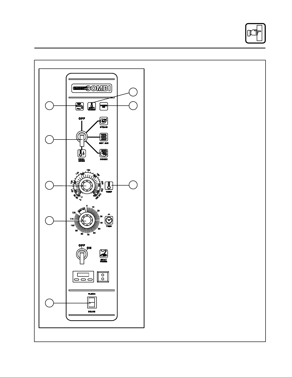
CombiĆOve /Steamer Sta dard Co trols
4
65
13
7
8
2
COSĆ8E with Meat Probe Shown
Figure 12
CONTROLS IDENTIFICATION
1. LOW WATER FILL LIGHT - during the fill
cycle, this light remains on until the water in
the steam generator is at the proper level and
up to temperature. During normal operation the
light should not be on. If the light comes on,
check the water level in the steam generator.
NOTE: COSĆ8EDS, the direct steam unit,
does not have a low water fill light.
2. DON'T STEAM LIGHT - indicates the unit is
too hot to operate in the steam mode. Place
the unit in the Cool Down mode until the temĆ
perature is below 230_F (110_C) and open the
door. This light does not inhibit steam producĆ
tion.
3. POWER ON LIGHT - indicates the unit is in
team, Hot Air or Combi.
4. MODE SELECTOR SWITCH - turns power
to the oven on or off. Allows selection of
team, Hot Air, Combi or Cool Down Modes.
5. TEMPERATURE DIAL - used to set desired
cooking temperature.
6. HEATING INDICATOR LIGHT - lights when
the Hot Air heating is in operation.
7. TIMER DIAL - used to set desired cooking
time.
8. FLUSH/DRAIN SWITCH - used to flush/
drain the steam generator for decalcification.
NOTE: COSĆ8EDS, the direct steam unit,
does not have a flush/drain switch.

Operatio
16
CombiĆOve /Steamer Sta dard Co trols
OPERATION
1. Turn the MODE ELECTOR witch (4) to the
desired function.
The POWER ON Light (3) illuminates.
2. et the TIMER (7) for the desired cooking time
or set it to STAY ON. The buzzer sounds and
the unit shuts off when the time has expired.
3. For the HOT AIR and COMBI modes, set the
TEMPERATURE Dial (5) to the desired cook
temperature. The HEATING INDICATOR Light
(6) illuminates and stays lit until the desired
temperature is reached. The temperature dial
does not operate during the TEAM portion of
the COMBI mode.
4. The selected mode operates automatically.
The temperature, time and mode can be alĆ
tered at any time during the cooking process.
The operation can be stopped by the use of
the Mode elector witch or by opening the
door.
5. At the end of the specified time period, the
buzzer sounds and the appliance shuts off auĆ
tomatically. Move the TIMER (7) to the STAY
ON position to stop the buzzer and restart the
unit.
6. To cool down the oven cavity, switch the
MODE ELECTOR witch (4) to COOL
DOWN. In the Cool Down mode neither the
temperature dial or the timer will be operationĆ
al. The blower will function with the door open
or closed.
7. The mode selector switch is also the main
power switch. In the OFF position the apĆ
pliance is not operational.
This manual suits for next models
4
Table of contents
Languages:


