2
INSTALLATION
Introduction
DESCRIPTION
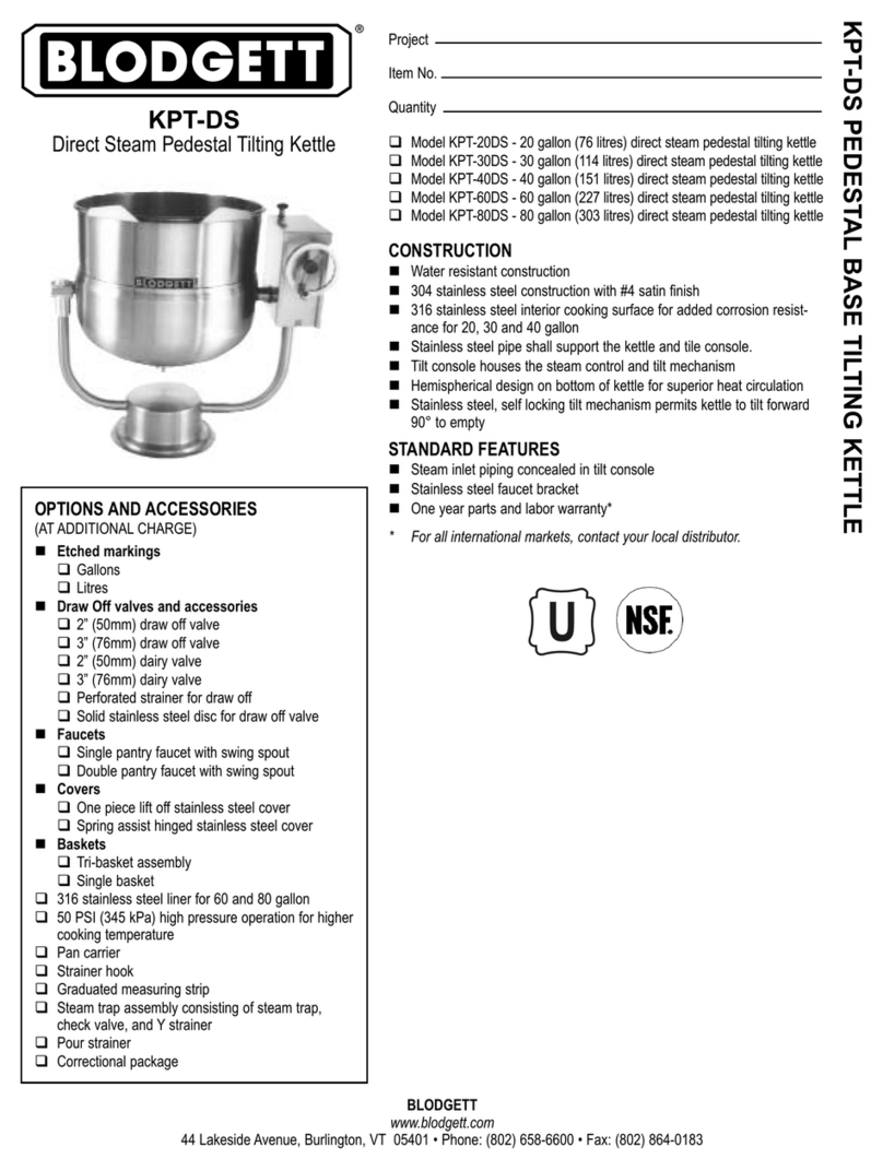
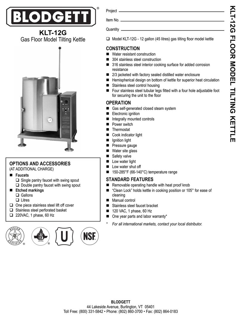
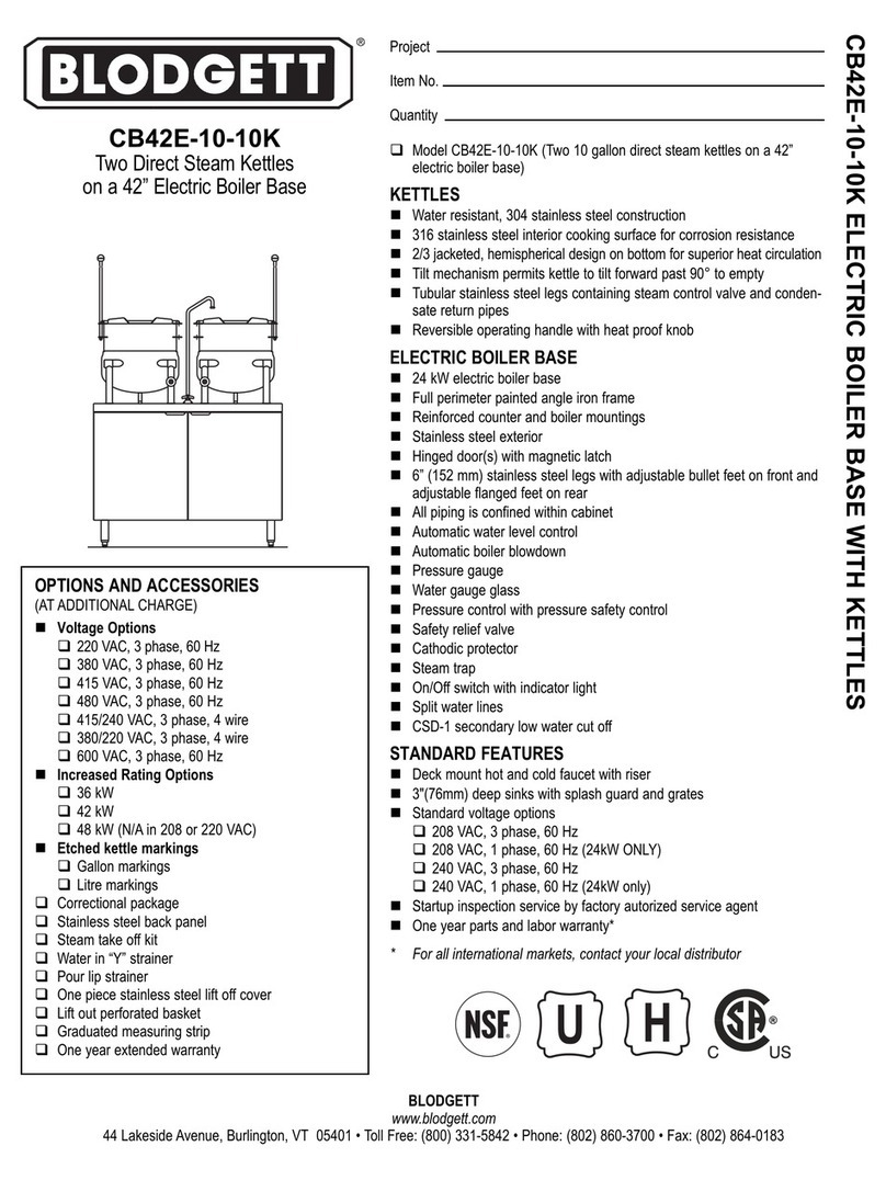
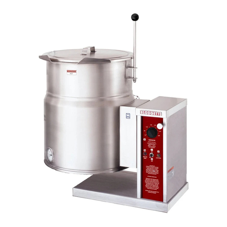
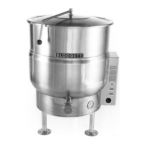
Floor model kettles are self-contained, self-generating
steam jacketed vessels for cooking large volumes of liq-
uid and semi-liquid food products. All models include a
hemispheric shape based on double-wall construction
forming a steam jacket reservoir around the lower two-
thirds of the kettle. The reservoir is charged with distilled
water, rust inhibitor and antifreeze solution and is vacu-
um-sealed. Kettles are equipped with electric heating ele-
ments and controls including a low water cut-o device for
protection of heating elements.
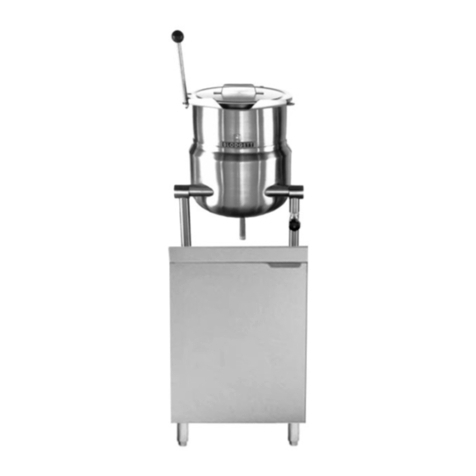
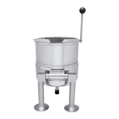
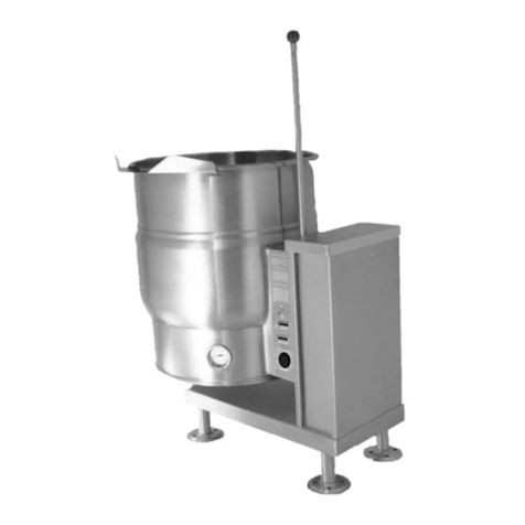
Two model series dier in that KLT-__E units are leg -
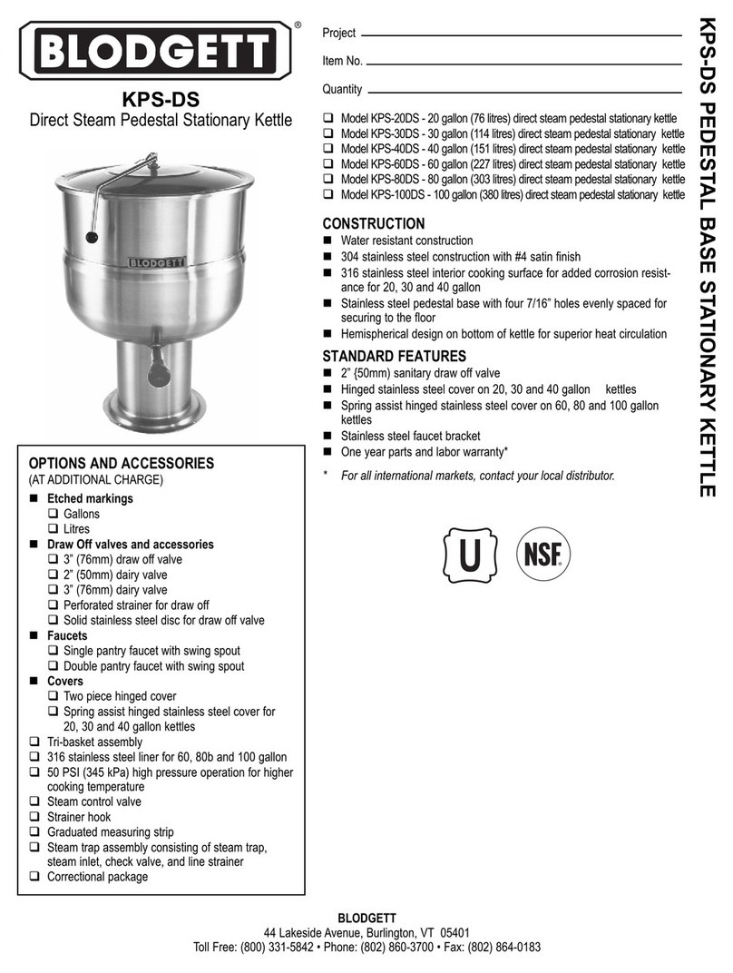
mounted tilting kettles while KPS-__E units are pedestal
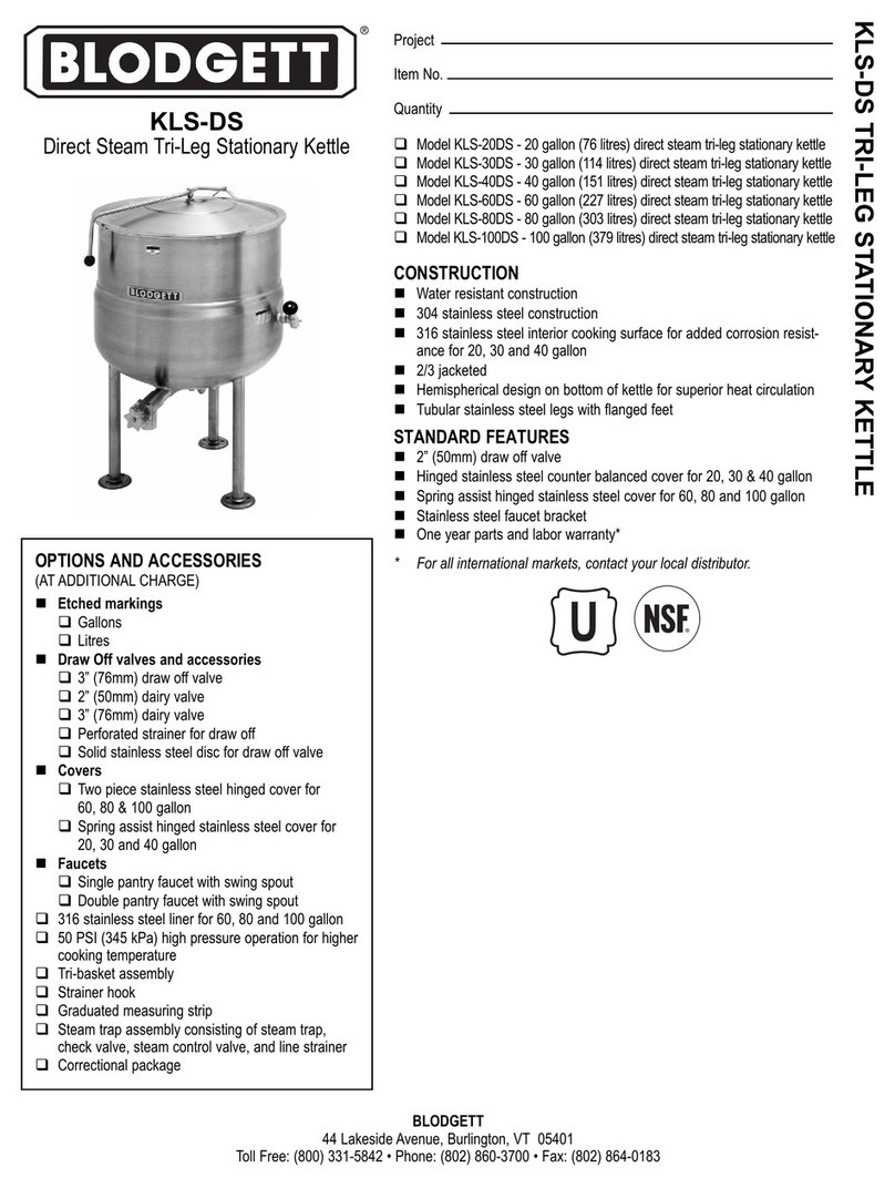
mounted stationery kettles. Optional leg mounting of the
pedestal models is designated by the model number se-
ries KLS-__E. The missing gures of the model numbers
are the two digits representing the kettle capacity, ie, KLT-
20E for a 20 gallon tilting kettle.
BASIC FUNCTIONING
Self-contained kettles operate by generating steam in the
kettle reservoir; the sequence of functioning, which oc-
curs during operation, is as follows:
1. Operator places the power switch in the ON position
and sets the thermostat knob at the required setting
from ‘’1’’ to”10” – 165°F (74°C) to 285°F (140°C ) -
jacket temperature.
2. Control circuit is normally completed to the thermo-
stat control if two standard conditions exist:
a. Water level in kettle jacket is adequate to’ prevent
circuit interruption by the low water cut-o device.
An activated cut-o is evidenced by the
Low Water light turning on and heating element
cut o.
b. Kettle is in vertical position with circuit complet-
ed through the tilt interlock switch (KLT-E series
only).
3. Thermostatic control contacts close to energize heat-
er contactor coils and turn temperature Indicator light
on.
4. Power is applied to heaters through closed contactor
power contacts.
5. As temperature of water rises in kettle reservoir, the
steam pressure increase is indicated by the vacuum
pressure gauge.
NOTE: Gauge normally reads 22-30 IN. Hg (74-100
k/Pa) (below 0 PSI, prior to heaters turning
on. Air is eliminated from the system when
jacket is lled (with the kettle reservoir at a
pressure above 0 PSI) by opening the bleed
vent one full turn for 10 seconds and closing.
6. When temperature of steam in the reservoir reaches
the temperature coinciding with the thermostat set-
ting, the thermostat switch opens to break the circuit
to the contractor coils and shuts o the elements. Any
number of on and o cycles of the control thermo-
stat, contactors and elements will occur as required
to maintain thermostat setting,
SERVICE
Required service, both preventive and corrective. is ex-
plained in the maintenance section. Should repairs be
required, a network of authorized agencies is available
to assist with prompt service. A current Directory of Au-
thorized Service Agencies may be found by visting our
website, www.blodgett.com.
The model and serial numbers must be referenced when
corresponding with Blodgett. The data plate containing
the serial number pertaining to the equipment is located
on rear of kettle.
