Blue Marble OSTRA User manual

1
Installation manual
Made in the Netherlands

2 3
Contents
1 Introduction 3
2 About the manual 4
3 Product description 6
4 Conditions for installation of the OSTRA 12
5 Installation of the OSTRA 13
6 Mounting of the OSTRA Pole/OSTRA Column 28
7 Commissioning of the OSTRA Charging Controller 40
8 Use of the OSTRA 50
9 Maintenance and faults 52
10 Manually unlocking the Type 2 socket 56
11 Declaration of conformity 58
OSTRA is the smart charging station with a single socket for charging electric
vehicles.
This manual contains the information necessary to install and use the OSTRA.
Read the instructions in this installation manual through carefully before you
start. Please also keep this installation manual for future use.
If you have any questions or need any help, please contact your sales
representative, the installer or go to www.ostracharger.com.
1. Introduction

4 5
2. About the manual
You are now reading the OSTRA installation manual. This manual contains
instructions for the OSTRA regarding installation, use and maintenance, in
that order.
OSTRA is a smart charging station, specially equipped with a socket for
charging electric vehicles (suitable for connection to Type 2, mode 3).
The purpose of this manual is to adequately inform everyone involved in
installing, connecting and maintaining the OSTRA. This will ensure that
your charging station is installed, used and maintained safely. Installation
is therefore only possible after reading this manual; this also applies to
accredited installers.
Please note: Installations may only be carried out by people who meet the
suitability requirements for working on electrical installations.
2.1 Structure of manual
The manual starts with instructions about the manual itself.
This is followed by general information about the OSTRA charging station
(section 3), followed by section 4 with conditions for the installation. These
must be observed in order to install the OSTRA correctly; something that is
explained in section 5.
If you are not mounting the charging station to a wall, section 6 will explain
how to install accessories such as the OSTRA Pole or the OSTRA Column.
The OSTRA Charging Controller is then discussed in section 7, followed by
‘correct use’ in section 8.
Section 9 contains guidelines for maintenance and faults. This is followed by
the manual unlocking of the Type 2 socket (section 10) on account of mainte-
nance conditions.
Finally, section 11 contains the conformity declaration of the manufacturer,
BlueMarble Charging B.V.
A B C D E F1
F2
CEMENT
i
!
A B C D E F1
F2
CEMENT
i
!
2.2 Guide to symbols
This manual uses the following symbols:
Caution, Electricity! Careless acts or failure to observe the
guidelines could result in a life-threatening electric shock.
Caution, Danger! Careless acts or failure to observe the guidelines
could result in physical injury or damage to the product.

6 7
3. Product description
3.1. OSTRA
OSTRA is a smart charging station for charging electric vehicles. A charging
station always consists of an OSTRA Charging Controller together with one or
more OSTRAs which are congured and connected together. Together, this
forms the intelligent heart of your charging infrastructure.
Depending on the implementation, an OSTRA Charging Controller up to 100
OSTRAs can form a smart charging network and connect wirelessly to each
other, divided between a maximum of 10 groups of charging stations.
3.2 Connecting with back ofce (myOSTRA)
To connect the OSTRA with a back ofce, an OSTRA Charging Controller is
required. The OSTRA Charging Controller is provided as an external accessory,
so does not form part of the charging point itself. OSTRA can also be equipped
with an OSTRA Internal Charging Controller as an optional extra, to create a
stable 4G connection.
3.3 Conditions for use
The OSTRA will only charge a vehicle when:
– The charging cable is connected to both the vehicle and the OSTRA, via
both plugs at the ends*;
– A valid charging card has been presented to the OSTRA RFID-reader (does
not apply to the OSTRA versions Plug & Charge and Connect & Charge);
– Authorisation has been granted by the back ofce** (does not apply to the
OSTRA Plug & Charge);
– The vehicle has accepted the charging session.
* To enable power to the socket, both charging cable plugs must be inserted in both the OSTRA and the vehicle
and authorisations have been granted.
** OSTRA models connected to myOSTRA via an OSTRA Charging Controller can also start a charging session by
means of a start/stop command from the myOSTRA back ofce.
3.4 Switching the OSTRA on and off
Following installation, the OSTRA can be switched on by the relevant circuit
breaker. You can make OSTRA voltage-free, and therefore switch it off, by
switching off that same circuit breaker.
3.5 Intentional and unintentional use
OSTRA is only suitable for charging Mode-3-compatible electric vehicles.
3.6 Technical specications
Technical specications
Charging capacity* Max. 3.7 / 7.4 / 11 / 22 kW
Charging mode Mode 3
Socket Type 2, IEC 62196-2
(optionally a xed Type-2 charging cable)
Number of sockets 1
Quality marks CE Declaration of Conformity
Main connection single-phase or three-phase,
230V–400V,
16A and 32A
Internal safeguard
against overcurrent
DC 6mA (DC leakage current)
AC 30mA leakage current detection (conguration
setting)
kWh measurement Standard embedded kWh meter
Optional MID-certied kWh meter for business
transactions
Ambient temperature -25°C to +50°C

8 9
Air humidity Max. 95%
Authorisation** Auto Start of RFID card
Status information LED indicator
Communication** Stand-alone
External OSTRA Charging Controller
Internal OSTRA Charging Controller with SIM card
Communication protocol OCPP 1.6J
Designed in accordance with IEC 61851-1 (2011),
EC 61851-22 (2002)
Protection rating IP65 (OSTRA Base),
IP54 (OSTRA Perla,
IK10
Installation requirements NEN 1010
Cable entry Via the underside, with a strain relief
Cable connection Terminal block for power cable with:
xed core: max. 6 mm2
flexible core: max. 10 mm2
Housing Polycarbonate (PC)/ABS
Dimensions in mm 370 x 135 x 210 mm
Weight 3.4 kg
Mounting Wall, on pole or built-in
Standard colours RAL 7021 Black-grey, RAL 9010 Pure white
* The maximum charging capacity of 22 kW is determined by the resistance of the charging cable, the maxi-
mum permissible charging capacity of the vehicle and OSTRA’s fuse protection.
** Depending on the OSTRA model
3.8 Installation, use and maintenance instructions
The safety instructions below apply to the installation and use of the charging
station. Read these instructions carefully and make sure that they are
followed.
3.8.1 Installation
– Only install the OSTRA on a suitable supply circuit while complying fully
with local technical requirements and safety regulations.
– Do not install an OSTRA in an environment of explosive and/or highly
flammable substances.
– Do not install an OSTRA in areas susceptible to flooding without taking
additional measures.
– When attaching to a wall, the load-bearing capacity must be at least 40 kg.
– The location of the installation must have an even and sturdy surface.
3.7 Specications per type of OSTRA
OSTRA
Plug &
Charge
OSTRA
Home
OSTRA
Home &
Work
OSTRA
Business
UTP-P1
OSTRA
Business
PoE
OSTRA
Business
4G
OSTRA
Satellite
1-3 fase 32A ✓ ✓ ✓ ✓ ✓ ✓ ✓
Type 2 socket ✓ ✓ ✓ ✓ ✓ ✓ ✓
Type 2 xed cable O O O O
DC 6mA leakage cur-
rent detection
(see section 4)
✓ ✓ ✓ ✓ ✓ ✓ ✓
AC 30 mA leakage
current detection
(see section 4)
✓ ✓ ✓ ✓ ✓ ✓ ✓
RFID card reader ✓ ✓ ✓ ✓ ✓ ✓
RF technology ✓ ✓ ✓ ✓ ✓ ✓
Internal kWh meter ✓
MID-certied 3-phase
kWh meter
✓ ✓ ✓ ✓ ✓
OSTRA Charging
Controller
N/A UTP-P1 UTP-P1 UTP-P1 PoE 4G N/A
Autostart ✓
O = Optional

10 11
– Preferably do not install the OSTRA in bright sunlight and in a location with
an ambient temperature of -25 to max. +50 degrees Celsius.
– Make sure that the location of the OSTRA is such that users can use their
charging cable without putting strain on it (i.e. pulling it taut).
– Installation cables must be laid on the basis of the maximum charging cur-
rent at the input to the charging station. Assume a continuous maximum
load. The cable diameters in this manual are an indication. The installer is
responsible for determining the correct cable diameter for connecting the
OSTRA and satisfying the relevant standards and regulations.
– Make sure that the charging cable is unable to come into contact with heat
sources.
– Make sure that the charging cable cannot become warped or wedged stuck
and cannot pose a tripping hazard for the environment.
3.8.2 Use
– Make sure that the equipment is used under the right operating conditions.
– Make sure your hands are dry when inserting or removing the plugs.
– Always pull on the grip of the plug, never the cable.
– In the event of damage and/or accidents, the charging station must be
made voltageless right away.
– Make sure that the charging cable isn’t warped or wedged stuck, cannot be
driven over and doesn’t pose a tripping hazard for the surroundings.
– In the case of an OSTRA with a xed charging cable, unwind the charging
cable completely during charging and avoid loops.
– Make sure that none of the plug ends can come into contact with water.
3.8.3 Maintenance
– Always make sure that the OSTRA is voltageless for carrying out mainte-
nance work and other work; only the OSTRA Front and the OSTRA Perla
(see image 5.1.2) can be mounted, dismounted and replaced whilst
electried (OSTRA hot-swap technology).
– Wait at least 10 seconds after disconnecting the OSTRA from the power
connection. The OSTRA may still contain electric charge immediately after
disconnecting.
– Only allow work to be carried out by a qualied employee. This person
must have read the manual, and act in accordance with standard IEC
60364 (Electrical Installations for Buildings). Failure to do so can result in
injury or hazardous situations when working with electricity with a risk of
life-threatening electric shock.
– The work must not be carried out if it is raining or if the air humidity is
higher than 95%.
– Do not use any powerful water jets or aggressive cleaning agents for
cleaning.
3.9 Warranty
BlueMarble Charging B.V. guarantees the equipment and software against
production faults and material defects and craftsmanship for two years from
the date of delivery. Accessories such as charging cards and power adapters
have a one-year warranty.
Problems arising from causes not attributable to the manufacturer are the
responsibility and risk of the installer and/or customer.
Examples of these causes are:
– The instructions in this manual have not been followed;
– The charging station has not exclusively been used to charge
Mode-3-Compatible electric vehicles;
– The installation has not been carried out by an accredited installer;
– You have made changes to the product yourself;
– Third parties have damaged the OSTRA (vandalism).
Consult the general terms and conditions and the full warranty conditions at
www.bluemarblecharging.com.

12 13
5. Installation of the OSTRA
The OSTRA charging station comes in two versions:
1. OSTRA charging station with Type 2 socket
2. OSTRA charging station with xed charging cable equipped with a
Type 2 plug
Choose a suitable and even wall on which to attach the OSTRA (for precise
instructions: see section 3.8).
material
treatment
project number
status
part name
project name
client units am.
date
tolerances according to
sheet
drawing number
scale
drawn
size
mod.
mm A3
Noordeinde 2d
2311 CD Leiden
the Netherlands
mod. date mod. bydescription modification
unless otherwise stated
by
proj.
T
F
E
+31 [0] 71 514 13 41
+31 [0] 71 513 04 10
-mail
n p k | design
DRW0001
Charger, main assy - IMAU
- -
- 2135 1/1 11:100
DRW0001 1
for information only
OSTRA charging station with Type 2 socket
OSTRA charging station with xed charging cable equipped with a
Type 2 plug
It must be possible to make a charging station voltageless automatically using
an earth switch if a leakage current is detected. The residual current device
(type A or type B, depending on the local regulations) must be incorporated in
the technical installation or may form part of the charging station depending
on the type of OSTRA component. Every model of OSTRA is equipped with a
DC 6 mA and AC 30 mA leakage current detection as standard.
The OSTRA charging station must be connected and installed by an
accredited installer. Installer and owner are responsible for the installation,
operation and maintenance to the OSTRA. Obey the law for the safety of
people, animals and goods (in NL NEN 3140), as well as the statutory installa-
tion regulations for the country in question.
Have the installer clearly mark what circuit breaker is linked to the OSTRA.
The OSTRA is suitable for wall, pole and column mounting as standard and
optionally as built-in. An installation height between 950 mm and 1500 mm is
recommended at all times.
For built-in, please contact BlueMarble Charging B.V.
– Section 5.6 for wall mounting
– Section 6.1 for mounting to OSTRA Pole
– Section 6.2 for mounting to OSTRA Column
4. Conditions for installing the OSTRA

14 15
5.1 Parts of the OSTRA
5.2 Installation tool
Use the following tools and materials for the installation:
– Wire stripper
– Pliers
– Hex Screwdriver (3 mm)
– Torx Screwdriver (size T25)
– Measuring tape
– Cutter
– Hammer drill or impact drill (for wall attachment)
– Drill bit (6 mm)
– Spirit level
– Voltage detector screwdriver
– End sleeve if there is a power cable with a flexible core
Bags of fasteners
A B C D
E F1
F2
CEMENT
i
!
A B C D
E
F1
F2
CEMENT
i
!
A B C D E
F1
F2
CEMENT
i
!
A B C D E F1
F2
CEMENT
i
!
material
treatment
project number
status
part name
project name
client units am.
date
tolerances according to
sheet
drawing number
scale
drawn
size
mod.
mm A3
Noordeinde 2d
2311 CD Leiden
the Netherlands
mod. date mod. bydescription modification
unless otherwise stated
by
proj.
T
F
E
+31 [0] 71 514 13 41
+31 [0] 71 513 04 10
-mail
n p k | design
DRW0001
Charger, main assy - IMAU
- -
- 2135 1/1 1:20
DRW0001 1
for information only
OSTRA Front
OSTRA Perla
OSTRA Base
Cable clamp parts
OSTRA Cover
An OSTRA charging station consists of:
– OSTRA Base
– OSTRA Cover (transparent)
– OSTRA Perla
– OSTRA Front
– Cable clamp
– Cutting gland
– Bags with fastening materials
– OSTRA Charging Controller (depending on the OSTRA model)
– OSTRA User interface sticker and infographic
– Charging Station Identier Label (C) and infographic
– OSTRA drilling template
A B C D E F1
F2
CEMENT
i
!
A B C D E F1
F2
CEMENT
i
!
A B C D E F1
F2
CEMENT
i
!
A B C D E F1
F2
CEMENT
i
!
A B C D E F1
F2
CEMENT
i
!
A B C D E F1
F2
CEMENT
i
!
A B C D E F1
F2
CEMENT
i
!
A B C D E F1
F2
CEMENT
i
!
A B C D E F1
F2
CEMENT
i
!
A B C D E F1
F2
CEMENT
i
!
A B C D E F1
F2
CEMENT
i
!
A B C D E F1
F2
CEMENT
i
!
5.2.1
5.1.1

16 17
5.3 Preparing the power cable
A B C D E F1
F2
CEMENT
i
!
A B C D E F1
F2
CEMENT
i
!
A B C D E F1
F2
CEMENT
i
!
A B C D E F1
F2
CEMENT
i
!
A B C D E F1
F2
CEMENT
i
!
Strip the outer cover of the 3 or 5-wire power cable to 450 mm so that the
internal coloured power cables become visible. Then strip the internal cables
to expose the core. If applicable, nish the soft core with suitable end sleeves
(not provided). (image 5.3.1).
450 mm
5.3.1
A B C D E F1
F2
CEMENT
i
!
A B C D E F1
F2
CEMENT
i
!
A B C D E F1
F2
CEMENT
i
!
Slide the cable clamp over the power cable as indicated in the image above.
Pay attention to the minimum and maximum protrusion length of the power
cable: min. 35mm/max. 45mm. Make sure that the clamp (arrow A) is pressed
rmly whilst the screw is being tightened (arrow B). The cable clamp is now
fastened to the cable (image 5.4.1).
Screw: KN6038 5x50 (T25)
A
B C D E F1
F2
CEMENT
i
!
5.4.1
Min 35 mm
Max 45 mm A
B
5.4 Mounting of the cable clamp
! Caution
Fix the cable clamp at the correct height compared to the stripped part
(image 5.4.1).
Torx
T25

18 19
5.5 Connection of the cables to the terminal block
Connect the cables as indicated in image 5.5.1.
5.5.1
5.6 Wall mounting of the OSTRA
A B C D E F1
F2
CEMENT
i
!
ABCDEF
1
F
2
CEMENT
i
!
950 - 1400 mm
300 mm
78 mm
6 mm
A B C D E F1
F2
CEMENT
i
!
50 mm
A
B
C D E F1
F2
CEMENT
i
!
5.6.1
A B C D E F1
F2
CEMENT
i
!
A B C D E F1
F2
CEMENT
i
!
ABCDEF
1
F
2
CEMENT
i
!
ABCDEF1
F2
CEMENT
i
!
ABCDEF1
F2
CEMENT
i
!
ABCDEF1
F2
CEMENT
i
!
Plugs: Muurplug 6x50
Screws: DIN7981CZ ST4,2x50
ABCDEF1
F2
CEMENT
i
!
ABCDEF1
F2
CEMENT
i
!
ABCDEF1
F2
CEMENT
i
!

20 21
! Caution
Check the position of the indicated drill holes using a measuring tape.
The distances between the drill holes horizontally and vertically are 300
mm and 78 mm respectively.
Using a spirit level and the drilling template provided, make sure that the
attachment to the wall is horizontal. Insert the cable into the housing from
the back and place the cable clamp in the housing. Now mount the OSTRA
to the wall using the fastening materials from bag B. Make sure that by tighte-
ning, the OSTRA Base does not warp or buckle, or does so as little as possible.
Cut out the gland to make a suitable seal between the cable and the gland.
Feed the power cable through the gland and make sure that the gland is
orientated correctly, as indicated in the image.
! Caution
The orientation of the gland (can be found in bag A) is important.
A B C D E F1
F2
CEMENT
i
!
5.7.1
A
B C D E F1
F2
CEMENT
i
!
5.7 Mounting of the cutting gland

22 23
5.8 Connection of the cables to the terminal block
A
B
C D E F1
F2
CEMENT
i
!
A B C D E F1
F2
CEMENT
i
!
Connect the cables as indicated in image 5.8.1.
Use the tie-wraps from bag B to mount the cabling in the OSTRA Base and to
tie it together. Cut off the excess pieces of tie-wrap for an attractive nish.
5.8.1
material
treatment
project number
status
part name
project name
client units am.
date
tolerances according to
sheet
drawing number
scale
drawn
size
mod.
mm A3
Noordeinde 2d
2311 CD Leiden
the Netherlands
mod. date mod. bydescription modification
unless otherwise stated
by
proj.
T
F
E
+31 [0] 71 514 13 41
+31 [0] 71 513 04 10
-mail
n p k | design
DRW0001
Charger, back housing, assy - IMAU
- -
- 2135 1/1 1:2
DRW0001 0
for information only
PE N L1 L2 L3
! Caution
The cable clamps are suitable for connecting 6 mm2 xed or 10 mm2
flexible core power cables.
5.9 Installation of the OSTRA Cover
A B C D E F1
F2
CEMENT
i
!
A B
C
D E F1
F2
CEMENT
i
!
Place the OSTRA Cover over the power cable, terminal block and the optio-
nal kWh meter and make sure that no cables become jammed between the
OSTRA Cover and the OSTRA Base. Press the OSTRA Cover into the OSTRA
Screw: DIN912 M4x20
ABCDEF
1
F
2
CEMENT
i
!
ABCDEF
1
F
2
CEMENT
i
!
ABCDEF
1
F
2
CEMENT
i
!
ABCDEF
1
F
2
CEMENT
i
!
5.9.1
3 mm
Hex
screwdriver

24 25
! Caution, Danger
Screw by hand, not electrically.
! Tip
Half mount all screws before tightening them completely. After mounting
the 4 screws, they can be rmly tightened.
A B C D E F1
F2
CEMENT
i
!
5.10 Mounting of the OSTRA Perla
Screw: DIN912 M4x12
A B C D E F1
F2
CEMENT
i
!
A B C
D
E F1
F2
CEMENT
i
!
5.10.1
5.10.1.a
A
B
Place the attachment hooks of the OSTRA Front in the notches on the top of
the OSTRA Perla. By rmly pressing the OSTRA Front when tightening the
screws, ensure a good connection between the OSTRA Front and the OSTRA
Base. Do not use any electrical tools for this.
! Tip
Start the assembly in the left corner and proceed with a crisscross moun-
ting pattern.
! Caution, Danger
Before installing the Perla, rst check the presence of a rubber O-ring
(arrow A) and the rubber plug (arrow B) on the back of the OSTRA Perla,
indicated in image 5.10.1.a.
A B C D E F1
F2
CEMENT
i
!
Base until it clicks into place and then tighten the OSTRA Cover using the
fastening materials from bag C.
3 mm
Hex
screwdriver

26 27
5.11 Mounting of the OSTRA Front
Orientate the OSTRA Front such that the attachment hooks fall in the OSTRA
Perla’s notches. Use the fastening materials from bag E and fasten to the
bottom of the OSTRA Front.
In the case of an OSTRA with a xed cable, the charging cable must be inser-
ted through the OSTRA Front rst (image 5.10.2). Orientate the OSTRA Front
such that the attachment hooks fall in the OSTRA Perla’s notches. Use the
fastening materials from bag E and fasten to the bottom of the OSTRA Front.
Screw: DIN912 M4x8
Screw: DIN912 M4x8
A B C D E F1
F2
CEMENT
i
!
A B C D
E
F1
F2
CEMENT
i
!
A B C D E F1
F2
CEMENT
i
!
A B C D E F1
F2
CEMENT
i
!
A B C D E F1
F2
CEMENT
i
!
A B C D E F1
F2
CEMENT
i
!
5.11.2 OSTRA Front mounting of an OSTRA with a xed cable
Place the attachment hooks of the OSTRA Front in the notches on the top of
the OSTRA Perla. By rmly pressing the OSTRA Front when tightening the
screws, ensure a good connection between the OSTRA Front and the OSTRA
Base. Do not use any electrical tools for this. Ensure a good connection be-
tween the OSTRA Front and the OSTRA Base by rmly pressing the OSTRA
Front when tightening the screws.
5.11.1
5.11.2
! Caution, Danger
Screw by hand, not electrically.
Before tightening the screws, the OSTRA Front must be pressed onto the
OSTRA to prevent any cracks from forming around the OSTRA. Only then
can both screws be tightened.
A B C D E F1
F2
CEMENT
i
!
5.11.1 OSTRA Front mounting of an OSTRA with a socket
3 mm
Hex
screwdriver

28 29
In addition to wall-mounting, an OSTRA can be attached to an OSTRA Column
or an OSTRA Pole. The OSTRA Column and OSTRA Pole are available in sever-
al designs.
Due to the wide variety of toughened surfaces, no fastening materials are
supplied to attach the OSTRA Column or OSTRA Pole to a toughened surface.
The installer will have to determine on location which fastening materials are
suitable for installing the OSTRA Column or the OSTRA Pole.
6. Mounting of the OSTRA Pole or
OSTRA Column
OSTRA Pole OSTRA Column
The OSTRA Pole is available in two different types:
1 - OSTRA Pole with xed ground anchor
2 - OSTRA Pole with foot plate
6.1.1 Installation of OSTRA Pole with xed ground anchor
6.1 Mounting of the OSTRA Pole
A B C D E F1
F2
CEMENT
i
!
A B C D E F1
F2
CEMENT
i
!
A B C D E F1
F2
CEMENT
i
!
A B C D E
F1
F2
CEMENT
i
!
60 cm
A B C D E F1
F2
CEMENT
i
!
6.1.1
material
treatment
project number
status
part name
project name
client units am.
date
tolerances according to
sheet
drawing number
scale
drawn
size
mod.
mm A3
Noordeinde 2d
2311 CD Leiden
the Netherlands
mod. date mod. bydescription modication
unless otherwise stated
by
proj.
T
F
E
+31 [0] 71 514 13 41
+31 [0] 71 513 04 10
-mail
n p k | design
DRW0002
Charger post assy, single charger - IMAU
- -
- 2135 1/1 3:50
DRW0002 1
for information only

30 31
! Tip
If the surface is loose, use of additional sand cement is recommended
(not provided).
The OSTRA Pole with a xed ground anchor is suitable for locations whether
there isn’t a xed surface. Go through the following steps to install an OSTRA
Pole with xed ground anchor:
1. Guide the cable through the underside of the pole to the top.
2. Install the pole, taking into account the thickness of any paving.
3. Connect the OSTRA charging station (see paragraphs 5.2 to 5.10, excl.
5.6) and attach the OSTRA to the OSTRA Pole using the fastening materi-
als from bag F-1.
6.1.2 Installation of OSTRA Pole with foot plate
The OSTRA Pole with foot plate comes with a foot plate with holes for a bolt-
nut connection for installation on a toughened surface. To install an OSTRA
with foot plate, carry out the following steps:
1. Determine the location of the pole and prepare the attachment points in
the surface.
2. Guide the cable through the underside of the pole to the top.
3. Attach the pole to the surface. The fastening materials are not provided.
4. Connect the OSTRA and attach the OSTRA to the pole using the fastening
materials from bag F-1.
material
treatment
project number
status
part name
project name
client units am.
date
tolerances according to
sheet
drawing number
scale
drawn
size
mod.
mm A3
Noordeinde 2d
2311 CD Leiden
the Netherlands
mod. date mod. bydescription modication
unless otherwise stated
by
proj.
T
F
E
+31 [0] 71 514 13 41
+31 [0] 71 513 04 10
-mail
n p k | design
DRW0002
Charger post assy, single charger - IMAU
- -
- 2135 1/1 3:50
DRW0002 1
for information only
A B C D E F1
F2
CEMENT
i
!
A B C D E F1
F2
CEMENT
i
!
A B C D E F1
F2
CEMENT
i
!
6.1.2
A B C D E F1
F2
CEMENT
i
!
A B C D E F1
F2
CEMENT
i
!
A B C D E F1
F2
CEMENT
i
!

32 33
https://npkdesignbv-my.sharepoint.com/personal/lpicarelle_npk_nl/_layouts/15/Doc.aspx?sourcedoc={629ae13c-592a-4d18-bdfc-2f4d2f636441}&action=edit&wd=target%28setup.one%-
7Cad423c66-21fa-4dd3-9576-b3eb5444c301%2FMeeting%20Robert%2006-07-2020%7C825c36a5-4752-4797-95b5-7d7266990540%2F%29
A B C D E F1
F2
CEMENT
i
!
A B C D E F1
F2
CEMENT
i
!
A B C D E F1
F2
CEMENT
i
!
A B C D E F1
F2
CEMENT
i
!
A B C D E F1
F2
CEMENT
i
!
material
treatment
project number
status
part name
project name
client units am.
date
tolerances according to
sheet
drawing number
scale
drawn
size
mod.
mm A3
Noordeinde 2d
2311 CD Leiden
the Netherlands
mod. date mod. bydescription modification
unless otherwise stated
by
proj.
T
F
E
+31 [0] 71 514 13 41
+31 [0] 71 513 04 10
-mail
n p k | design
DRW0002
Business charger station, double access - -
- -
- 2135 1/1 1:5
DRW0002 1
for information only
! Tip
If the surface is loose, use of additional sand cement is recommended.
Installation of the ground anchor on a soft surface
An OSTRA Ground Anchor can be used to mount an OSTRA Column on a soft
surface. Go through the following instructions before installing an OSTRA
Column on an OSTRA Ground Anchor:
1. Go through the installation manual supplied with the ground anchor.
2. Position the ground anchor so that the top plate is horizontal and that top
of the ground anchor protrudes just above ground level. Take into account
the thickness of any paving.
3. Install the cable sleeve by guiding it through one of the holes in the base
plates or side plates and make sure that the power cable protrudes at
least 95 cm above ground level.
4. Preferably pour quick concrete, sand and soil in and around the ground
anchor. Fill to approx. 50 mm under the rim.
5. Guide the cabling through the cable sleeve.
6. Remove the front panel of the OSTRA Column*. Store the panel and screws
carefully!
7. Place the OSTRA Column on top of the ground anchor. The OSTRA Column
has four attachment holes (approx. 8 mm) for a screw connection with the
ground anchor in its foot. The fastening materials are supplied with the
ground anchor.
8. Make sure that the OSTRA Column is level and tighten the screws.
9. Attach the ground wire to the earth terminal of the ground anchor*.
The fastening materials are supplied with the ground anchor.
10.Repair the ground and level off with soil, sand and any paving.
60 cm
ABCDEF1
F2
CEMENT
i
!
ABCDEF1
F2
CEMENT
i
!
Screw: DIN912 M6x25
6.2.1
6.2 Mounting of the OSTRA Column

34 35
material
treatment
project number
status
part name
project name
client units am.
date
tolerances according to
sheet
drawing number
scale
drawn
size
mod.
mm A3
Noordeinde 2d
2311 CD Leiden
the Netherlands
mod. date mod. bydescription modification
unless otherwise stated
by
proj.
T
F
E
+31 [0] 71 514 13 41
+31 [0] 71 513 04 10
-mail
n p k | design
DRW0002
Business charger station, double access - -
- -
- 2135 1/1 1:5
DRW0002 1
for information only
Installation of OSTRA Column on toughened surface
You can screw the OSTRA Column to the ground through the holes in the base
of the OSTRA Column. Go through the following steps before mounting the
OSTRA Column on a toughened surface:
1. Decide on the location of the OSTRA Column and make sure you have a
suitable fastening option.
2. Remove the front panel of the OSTRA Column*. Store the panel and screws
carefully!
3. Guide the cable through the underside of the OSTRA Column to the inside.
4. Place the OSTRA Column in the required location. The OSTRA Column has
four attachment holes (approx. 8 mm) for a screw connection with a hard
surface in its foot.**
5. Make sure that the OSTRA Column is level and tighten the nuts.
* All parts of the OSTRA Column come with and are connected to a ground wire.
** Fastening materials are not provided.
6.2.2
A B C D E F1
F2
CEMENT
i
!
A B C D E F1
F2
CEMENT
i
!
A B C D E F1
F2
CEMENT
i
!
A B C D E F1
F2
CEMENT
i
!

36 37
material
treatment
project number
status
part name
project name
client units am.
date
tolerances according to
sheet
drawing number
scale
drawn
size
mod.
mm A3
Noordeinde 2d
2311 CD Leiden
the Netherlands
mod. date mod. bydescription modification
unless otherwise stated
by
proj.
T
F
E
+31 [0] 71 514 13 41
+31 [0] 71 513 04 10
-mail
n p k | design
DRW0002
Business charger station, double access - -
- -
- 2135 1/1 1:5
DRW0002 1
for information only
ABCDEF
1
F
2
CEMENT
i
!
ABCDEF
1
F
2
CEMENT
i
!
ABCDEF
1
F
2
CEMENT
i
!
1. Make sure that the working environment is safe and check that the instal-
lation and the power cable are voltageless.
2. Remove the lid from the junction box. Store the lid and screws carefully!
3. Check whether the grounding of the column and the panels are connected
properly. Each panel must be connected to the frame, and from here to the
earth terminal in the junction box.
4. Insert the power cable into the junction box using the gland provided
(M25*1.5 / 8-17 mm).
5. Connect the power cable to the terminals.
6. After connecting the power cables, replace the lid on the junction box
using the corresponding screws. Do not use electrical tools for this.
7. Return the front panel of the OSTRA Column to its original place. Turn the
screw sufciently into the frame so that the panel is unable to slide up-
wards or downwards.
The OSTRA Column can be connected in three ways.
A. Supply single power cable
B. Supply double power cable
C. Supply single power cable and loop through
6.3 Connection of the power cable
L3L3L2L1L1NNPEPE L2 L3L3L2L1L1NNPEPE L2
L3L3L2L1L1NNPEPE L2
6.3.1
ABCDEF
1
F
2
CEMENT
i
!
A. Supply single power cable B. Supply double power cable
C. Supply single power cable and
loop through
to the next Business column
1
1
1
1
OSTRA
OSTRA
OSTRA
1
1
1
1
1
1
1
1
1
1
1
1
1
1
1
1
1
1
1
1
1
1
1
1
1
1
2
2
2
2
2
2
2
2
2
2
2
2
2
2
2
2
2
2
2
2
! Caution, Danger
Screw by hand, not electrically.
A B C D E F1
F2
CEMENT
i
!
38 39
material
treatment
project number
status
part name
project name
client units am.
date
tolerances according to
sheet
drawing number
scale
drawn
size
mod.
mm A3
Noordeinde 2d
2311 CD Leiden
the Netherlands
mod. date mod. bydescription modification
unless otherwise stated
by
proj.
T
F
E
+31 [0] 71 514 13 41
+31 [0] 71 513 04 10
-mail
n p k | design
DRW0002
Business charger station, double access - -
- -
- 2135 1/1 1:5
DRW0002 1
for information only
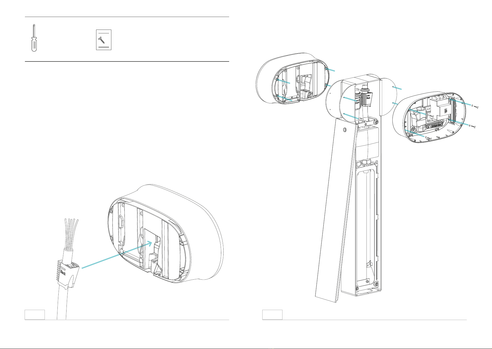
1. Prepare the strain relief as stated in section 5.3 and insert the supply
cable into the OSTRA.
2. Screw the OSTRA onto the OSTRA Column using the fastening materials
from bag F-2.
3. Go to section 5.6 for the further installation of the OSTRA(s).
6.4 Mounting of an OSTRA on the OSTRA Column
6.5.26.5.1
ABCDEF
1
F
2
CEMENT
i
!
ABCDEF
1
F
2
CEMENT
i
!
ABCDEF
1
F
2
CEMENT
i
!
ABCDEF1
F2
CEMENT
i
!
Screws: DIN912 M4X25
A B C D E F1
F2
CEMENT
i
!
3 mm
Hex
screwdriver
A B C D E F1
F2
CEMENT
i
!
This manual suits for next models
7
Table of contents


