Blue Sea Systems Battery LINK 7606 User manual
20A CHARGER
User Manual
7606
Read and understand the contents of this User Manual. It contains important safety, handling, and operational instructions for the
BatteryLink®Chargers. This User Manual describes the product mentioned herein at the time of its publication. Specifications and
performance are subject to change at the discretion of Blue Sea Systems. To view the most current revision of this publication visit
bluesea.com/products/7606.
Scan for
additional
product
information
YEAR
WARRANTY

Specifications are subject to change. See bluesea.com/products/7606 for current information.
1
IMPORTANT SAFETY INSTRUCTIONS
1. SAVE THESE INSTRUCTIONS
This manual contains important safety and operating instructions for the BatteryLink® Charger model 7606.
2. WARNING RISK OF EXPLOSIVE GASES. Working in the vicinity of a lead-acid battery is dangerous.
Batteries generate explosive gases during normal battery operation. For this reason it is of the utmost
importance that each time before using your charger, you read and follow the instructions provided exactly.
3.
TO REDUCE RISK OF BATTERY EXPLOSION,
follow these instructions and those marked on the battery.
4. This appliance can be used by children aged from 8 years and above and persons with reduced physical,
sensory or mental capabilities or lack of experience and knowledge if they have been given supervision or
instruction concerning use of the appliance in a safe way and understand the hazards involved.
5. Children should be supervised to ensure they do not play with the appliance.
6. WARNING AVOID SERIOUS INJURY OR DEATH FROM FIRE, EXPLOSION, OR
ELECTRICAL SHOCK. The BatteryLink® Charger is intended only for fixed installation by qualified
professionals. Improper installation can result in electrical shock, which may cause serious injury or death.
a. The BatteryLink® Charger is marked as “ignition protected” for operation in a small craft gasoline engine
space. HOWEVER: Connection or disconnection of any electrical cables may cause sparks, which could
ignite flammable gasses and cause explosion.
b. Never connect or disconnect electrical cables when explosive gasses may be present.
c. Always disconnect AC power sources before connecting or disconnecting the charger AC cord.
d. A circuit breaker or other means for disconnection from the supply mains must be incorporated in the
fixed wiring to the charger in accordance with wiring rules.
e. The AC supply cord should be protected by a Residual Current Device (RCD) suitable for personal shock
protection. Make AC connection in a secure manner that will avoid contact with water.
7. DO NOT OPERATE CHARGER IF IT HAS A DAMAGED CORD, has received a sharp blow, been
dropped, or otherwise damaged in any way. The supply cord cannot be replaced. If the cord is damaged,
the appliance should be scrapped.
8. USE CHARGER FOR CHARGING ONLY THESE 12V BATTERY TYPES: Flooded lead-acid, AGM, or TPPL.
Do not use your marine battery charger to charge non-rechargeable or dry-cell batteries that are commonly
used with home appliances. These batteries may burst and cause injury to persons and damage to property.
9. Be sure area around battery is well ventilated while battery is being charged. Keep open flames and sparks
away from batteries, as these may cause explosion.
10. Make or break DC output cable connections to battery only after making and verifying DC connections on
the charger, and disconnecting the AC supply to the charger.
11. Do not make or break electrical connections to batteries while charging or for up to 30 minutes after charging.
12. If a battery switch is installed, ensure battery switch is in the OFF position before making or breaking any
connections to the battery. If no battery switch is installed, ensure all accessories are OFF.
13. Charger should be grounded to reduce risk of electric shock. Charger is equipped with an electric cord having
an equipment-grounding conductor. The charger should be properly wired and grounded in accordance with all
local codes and ordinances.
14.For compliance with electromagnetic compatibility standard EN 55014-1:2006, DC out put cables must be
a fixed installation using non-extendable connectors such as ring terminals, and with maximum length
of 2 meters.
Specifications are subject to change. See bluesea.com/products/7606 for current information.
2
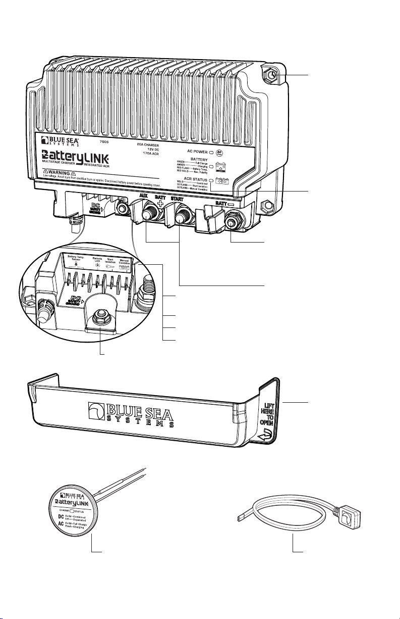
BATTERYLINK® CHARGER OVERVIEW
Charging and ACR
status LEDs
Battery Temperature
Sensor connection
Remote LED connection
Start Isolation connection
Mounting holes (4)
Clearance for #10 or
M5 mounting hardware.
Hex recesses accept
#10 (3/8" socket size)
nuts.
NOTE: Mounting holes
are not symmetrical,
please see dimensioned
drawing.
Terminations cover
snaps in place to
insulate terminations
MULTISTAGE CHARGER INTEGRATEDACR
Remote LED included Battery temperature
sensor included PN 1820
DC Output
Battery negative connection
1/4"-20 studs accept 1/4" or M6 ring
terminals. Use 7/16" socket wrench.
Tighten to 60 in-lb (6.78 Nm).
Do not overtighten.
Battery positive connections
3/8"-16 studs accept 3/8" or M10 ring
terminals. Use 9/16" socket wrench.
Tighten to 140 in-lb (15.8 Nm).
Do not overtighten.
NOTE: All accessory terminations
1/4" x 0.032" male quick connect
Manual Combine connection
DC Safety Ground
1/4"-20 stud accepts
1/4" or M6 ring terminals.
Use 7/16" socket wrench.
Specifications are subject to change. See bluesea.com/products/7606 for current information.
3
BatteryLink®Charger Features
The BatteryLink® Charger is a 120V AC/230V AC nominal input, 12V DC nominal output, 20A battery charger with
integral battery combiner (ACR) providing a second battery connection, as well as standard ACR function
when AC power is not present.
• AC plug-in at the dock, provides 20A of charge current
• Integrated ACR automatically combines batteries during charging, isolates batteries when discharging and
when starting engines
• Start isolation protects sensitive electronics from voltage sags and spikes
• Emergency jump start by using optional remote switch (not included) to combine both batteries if start battery is low
• Battery temperature compensation prolongs battery life
• Supports alternators up to 170A
• One-piece stainless flange nuts ensure safe and secure connections
• Ignition protected—safe for installation aboard gasoline powered boats
• Includes a remote indicator LED with mounting bezel
• Snap-on insulating cover
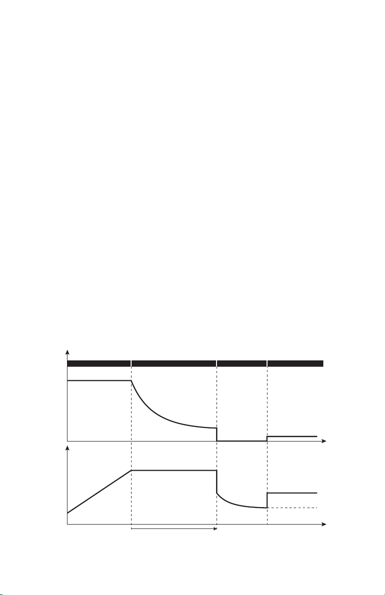
Automatic Three Stage Charging
The BatteryLink® Charger uses a three stage automatic charging profile. The three stages are referred to as bulk,
absorption, and rest/float. The charger will move between these stages automatically, with no user intervention. When the
charger starts, it goes first to the bulk stage. This is where the first 75% – 80% of charging takes place. It is a constant
current mode, in which the charger outputs as much current as it can to drive the voltage of the battery up to the
absorption voltage. Once the absorption voltage is reached, the charger enters absorption mode. This is a constant
voltage mode, in which the battery is held at the absorption voltage to complete the last 20% – 25% of charging. In the
absorption stage, current will decrease according to the batteries’ needs plus any additional current required for active
loads. The length of time spent in the absorption stage will vary based on battery type, battery capacity, and the pres-
ence of loads, but will be a minimum of 1 hour up to a maximum of 5 hours. Added loads causing the charger to reach
its current limit will result in transition back to bulk mode, and time will be added back to the absorption timer while in
bulk. After the absorption stage, the charger will move to the rest/float stage. The float stage is a constant voltage mode
intended to maintain fully charged batteries while supplying current for loads as necessary. The rest mode is included
as an energy saving mode, and for compliance with California Energy Commission (CEC) and U.S. Department of Energy
(DOE) requirements. In the rest stage, the charger output is turned off to conserve energy, and the battery voltages are
monitored. If loads or self-discharge on either battery cause the voltage to drop to 12.9V (temperature compensated),
the charger enters float mode for 4 hours in order to maintain the battery and supply current to loads. After seven days of
continuous operation, the charger will repeat the full charge cycle to ensure good battery health.
Bulk
Current
Max Current Limit
Absorption Voltage
Absorption ends after 1 hour if
current is <1A, or 5 hours max.
Float Voltage
Rest End Voltage
Time
Absorption FloatRest
Voltage
Time

Specifications are subject to change. See bluesea.com/products/7606 for current information.
7606
AC
4
Battery Temperature Compensation
Battery temperature compensation is output voltage regulation based on battery temperature variances. Since batteries
can see extreme temperature differences, it is important to regulate output voltage with temperature to maximize battery
life. A battery in a cold environment should not be charged at the same voltage as a battery in a hot environment. The
BatteryLink® Charger is set at a baseline of 25°C. If the included battery temperature sensor is installed, then any
variance from this baseline will result in a change in output voltage. Voltage will decrease at higher temperatures,
and increase at lower temperatures. The temperature sensor also allows the charger to react to extreme hot or cold
temperatures (below -20°C or above 45°C) by reducing output or shutting down to preserve the battery. Reference the
Installation Instructions on page 6 and the Full Installation Diagram on page 8 for details on how to install the battery
temperature sensor.
Automatic Charging Relay (ACR)
The BatteryLink® Charger includes an integrated 170A Automatic Charging Relay (ACR). The purpose of an ACR is to
combine batteries for charging, but leave them isolated for discharge. This works well with dual battery systems, where
non-starting loads are isolated from the engine starting battery to reduce the risk of being stranded on the water without
enough power to start your engine. The ACR in the BatteryLink® Charger will combine the auxiliary and start batteries at
or away from the dock. This means both batteries will be charged during AC powered charging, or when AC power is not
available and a secondary charging source is active, such as your engine’s alternator. The ACR includes an optional Start
Isolation feature, which can be used to prevent engine starting current being drawn from the auxiliary battery. Start
Isolation protects sensitive electronics wired to the auxiliary battery from being affected by voltage sags or spikes caused
by engine starting. The ACR also includes an optional Manual Combine feature, which allows manually closing the ACR
to parallel the batteries using a remote switch. This can be used to jump start from the auxiliary battery in the event of
a dead start battery. Reference the Installation Instructions on page 6 and the Full Installation Diagram on page 8 for
details on how to wire the Start Isolation and Manual Combine features.
LED Status Indicators
Green solid AC power
Off No AC power
Green solid Combined - ACR closed
2x-flash
SI present, battery temp outside range of
-20°C to 49°C, or reverse battery polarity
detected - ACR open
3x-flash Manual Combine input present - ACR closed
Off Battery voltages below threshold - ACR open
Green solid Charge complete -
Float/rest stage
Amber solid Charge in progress -
Bulk or absorption stage
Red
single blink
Battery hot - Charger shutdown
(>= 49°C, recovers at 47°C)
Red
double blink
Battery hot - Output reduction
(>= 45°C, recovers at 43°C)
Red
triple blink
Battery cold - Charger shutdown
(<= -20°C, recovers at -18°C)
Red solid Battery polarity reversed
Off No AC power
DC Power Solid Combined - ACR closed
Off Separated - ACR open
AC Power
Solid Charging complete - Float/rest stage
Flash Charge in progress - Bulk or absorption
Or error state - See charger LEDs
AC POWER BATTERY ACR STATUS
CHARGE STATUS
This manual suits for next models
1
Table of contents
Other Blue Sea Systems Batteries Charger manuals

Blue Sea Systems
Blue Sea Systems P12 Series User manual

Blue Sea Systems
Blue Sea Systems P12 Series User manual

Blue Sea Systems
Blue Sea Systems BatteryLINK 7605 User manual

Blue Sea Systems
Blue Sea Systems Battery LINK 7608 User manual
 User manual")
Blue Sea Systems
Blue Sea Systems 7521 (25A) User manual

Blue Sea Systems
Blue Sea Systems 7531 User manual


