Blueshape CVS8XW User manual

INTELLIGENT BATTERY CHARGER
FOR V-LOCK LITHIUM ION BATTERIES ONLY
Model
CVS8XW – Wall Mount
OPERATING INSTRUCTIONS
Revision 1.1
www. lueshape.net Printed in Malta 2016

Please read t ese instructions concerning your safety
BLUESHAPE lithium-ion attery chargers have een designed to
provide a superior performance y managing relatively high currents
during their operation in order to reduce charging time.
As may e expected, the chargers ecome warm during operation
and it is therefore very important to keep their ventilation openings
uno structed.
Moreover, please follow the safety instructions elow.
- Protect the equipment from humid environments. Avoid any
contact with water or other fluids. Do not use if any liquid has
een accidentally spilled inside the equipment .Contact qualified
service personnel for inspection or repair
- Clean only y using a dry cloth
- Unplug when not in use and avoid power surges
- Read the supplied instructions thoroughly and keep handy
- Avoid setting up near heat sources such as fire places, radiators,
stoves or other heat generating equipment
- NEVER use without proper grounding
- Protect the AC mains power plug, connector and cord
- If the equipment develops a fault, have it repaired y qualified
service personnel only
- NEVER lock the ventilation openings or o struct cooling fan air
flow
- Use only as instructed y the manufacturer
- Do not remove cover or dismantle the apparatus. No user-
servicea le parts inside
WARNING
THIS EQUIPMENT MUST BE EARTHED
TO PREVENT FIRE OR SHOCK HAZARD
DO NOT EXPOSE THE UNIT TO RAIN OR
MOISTURE
TO AVOID ELECTRIC SHOCK, DO NOT OPEN THE
APPARATUS AND ALWAYS REFER ANY SERVICING TO
QUALIFIED PERSONNEL
2

The user is eing alerted of the importance of
going through the literature accompanying this
product and familiarising himself with the
important safety and operating instructions,
included.
BLUESHAPE CHARGERS ARE INTENDED FOR OPERATION
WITH LINE VOLTAGES BETWEEN 100V AND 240V AC AND LINE
FREQUENCIES BETWEEN 43Hz AND 60 Hz
The equipment is eing supplied with a compati le AC mains power
cord. In the case when the UK plug is fitted, this plug is equipped with
a 13A replacea le fuse.
Package contents
- CVS8XW simultaneous eight position charger
- Wall hanging racket
- AC power cord
- Safety operating instructions
- USB data ca le to e used with BSCVMon software
downloada le from our we site at the following address:
http://www. lueshape.net/index.php/products/software/ sc
vmon.html
3

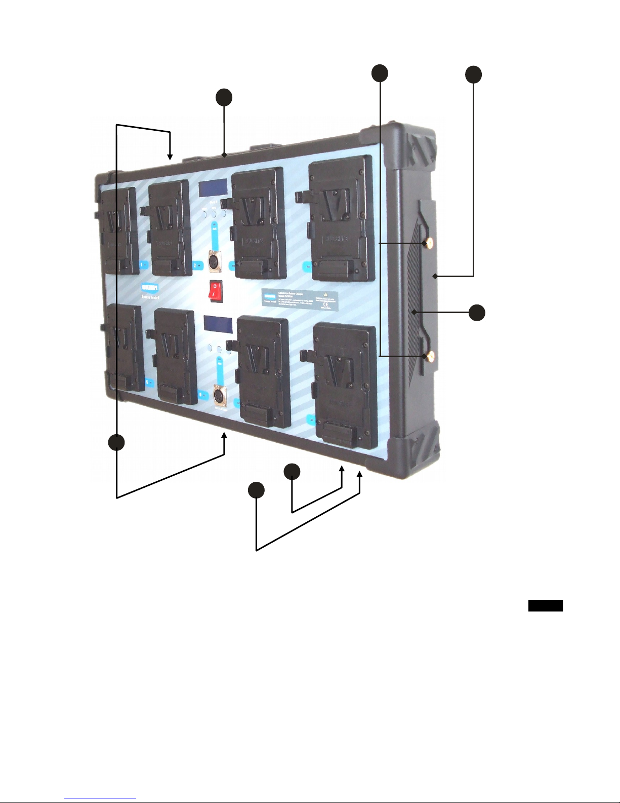
CVS8XW grap ic description – Front view
1. Upper Bank-A (channels from #1 to #4)
2. Battery charging ays
3. Battery LED indicators (see page 15 for explanation)
4. LCD display
5. LCD keys
6. AUX output LED indicator (see page 16 for explanation)
7. AUX output connector (13.8V 110W)
8. Mains switch
9. Lower Bank-B (channels from #5 to #8)
4
5
2
4 76 8
9
1 3
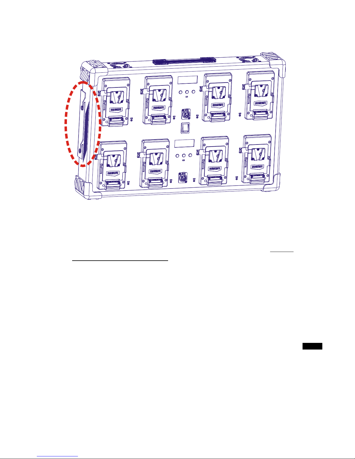
CVS8XW grap ic description – Side View
1. Carrying handle
2. Supporting lateral studs
3. Wall mount racket (see page 6 for explanation)
4. Ventilation inlets
5. Data connector
6. AC Mains input, 100V-240V
7. Ventilation outlets
5
4
1
23
6
5
7

Installation
This charger is designed to ideally e installed on a wall.
We suggest you identify a suita le site, where the charger can e
located allowing easy access and at the same time keeping the
ventilation inlets free from o struction:
- proceed with the mounting racket first:
- put the racket against the wall, and mark the 4 holes
- screws and/or fittings are not included: choose proper screws or
fittings to fix the racket to the wall that are specially suited to the
material in your wall and have sufficient holding power
- fix the racket firmly tightening all the 4 screws
- lift the charger and align the 4 lateral golden studs with the
corresponding slots on the mounting racket
6
- slide the studs in the slots carefully, then lower the charger to
seat it in its definitive position
- IMPORTANT- verify that that all the 4 studs are correctly and
firmly inserted in the related slots
- connect the AC power cord
- if needed, connect the USB data ca le to the PC before
switc ing-on t e c arger, to allow a correct detection and
initialization of the communication hardware.
The charger is now ready to operate.
7

Introduction
The BLUESHAPE series of intelligent lithium ion attery chargers has
een specifically designed for fast and relia le charging of the
BLUESHAPE V-lock attery range. All charger models are capa le
of delivering up to 4.8 Amps in constant current mode making them
particularly suita le to users who require a fast turnaround from their
atteries.
This charger has een designed for users having large fleets of
atteries, and with a higher daily rotation; the wall mounting feature
and the flat form factor makes it discrete and minimally intrusive in
any installation.
Properties of t e CVS8XW
- Elegant and ro ust design. Ideal for indoor use
- Sophisticated electronics for accurately detecting the charging
state
- Simultaneous attery charging, truly 8 channels without the need
of external adapters.
- Charging power optimisation for maximum charging performance
- Dou le colour LCD display and three-colour LED indicators for
effective and comprehensive individual charge-station monitoring
- Pre-charge function for protecting heavily discharged cells
against high currents until their voltages rise to a safe level.
- Maximum compactness and space utilisation
- IPCS and CTP Features (see next pages)
- Dual powerful auxiliary outputs at 13.8V / 110W through 4-pole
XLRs
- USB connection to interface the CVS8XW with a PC: up to 4
chargers can e monitored y a single PC using BSCVMon - a
custom Blueshape software for tracking and monitoring chargers
and logging attery fleet history.
- Redundant electronic design with 4 power supplies for increased
relia ility.
Battery c arging and performance features
The electronic circuitry provides a very accurate lithium ion charge
algorithm. Initially, the charger will only apply a pre-charge current of
a few milli-amperes to atteries that are heavily discharged. This
same current ena les the charger to detect the present attery state.
Once the cells inside the atteries reach a safe level, the full
(maximum) charging current is delivered until the attery reaches
almost 80% state of charge. After this, a constant voltage phase
egins with the charging current decaying slowly until full cut-off.
8

The following ta le descri e the charging time (in minutes) with
regards to attery model and num er of atteries installed. The
approximate charging time refers to charging atteries from empty.
Battery model up to 4 batteries installed
(all charging simultaneously)
more than 4 batteries installed
(all charging simultaneously)
BV065 55 91
BV090 76 126
BV100 D 76 126
BV150 125 207
BV180 150 248
BV190 D 165 273
BV225 188 310
BV270 D 225 372
The 8 channels are paired in this way:
chan 1-2, chan 3-4, chan 5-6, chan 7-8.
To achieve the fastest charge performance, install only one attery
on each pair of channels: in this way the charge current will reach
approx. 4.9A per attery ( ut no more than 0.8C) achieving a shorter
charge time.
Instead, if two atteries are installed on a pair of channels, the charge
current will e reduced to 3A per attery ( ut no more than 0.8C).
9

IPCS and fast c arging
The CVS8XW charger, similarly to the other product of BLUESHAPE
range, features the highest charging current for a Li-Ion charger in the
roadcasting sector.
This results in currently the shortest possi le attery charging time.
BLUESHAPE Li-Ion BV attery series allow fast charging due to
several intrinsic features such as pre-charge protection and cell
alancing; avoiding cell damage and life-cycle shortening, as
demonstrated y the life-cycle performances.
Additionally, the CVS8XW charger supports and enhances these
features with IPCS, a 2-step Intelligent Pre-Charge System.
Since fast charging can damage cells if not properly applied,
especially with low voltage (discharged) cells, appropriate care must
e taken. The 2-step procedure implemented y IPCS, initially oosts
very low voltage cells to a state where charge can e applied with a
medium-low current without damage, then starts to charge with a
300mA current for a while. Finally, when the pack reaches a
reasona le voltage state, it speed-up the charge process y going to
full throttle.
The operation implemented y IPCS is only applied if the prevailing
cells-state need it, and normally takes a few minutes, depending on
the state of discharge of the cells.
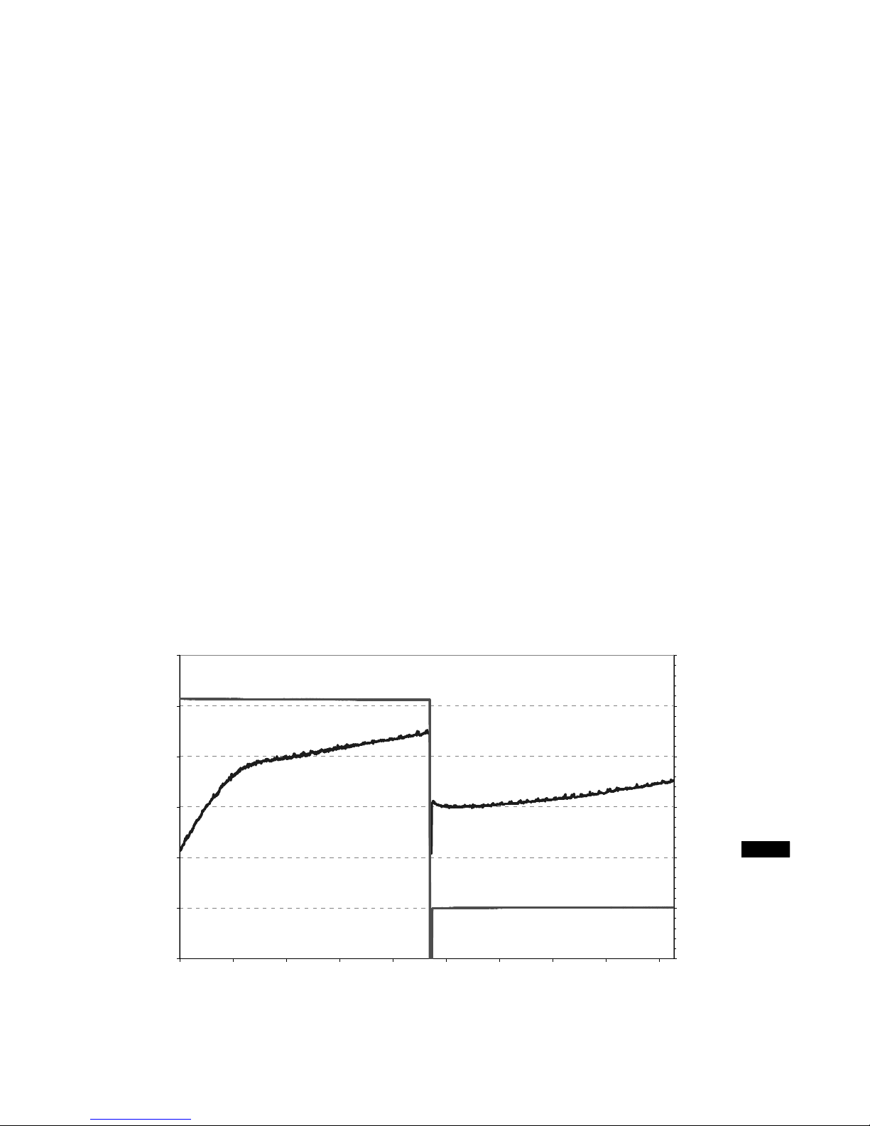
The operation implemented y IPCS is outlined in the chart elow.
IPCS 2-step Intelligent Pre-charge System
11000
11500
12000
12500
13000
13500
0 3 5 8 10 13 15 18 20 23
Time (min)
Voltage (mV)
0
100
200
300
400
Current (mA)
CURRENT
VOLTAGE
Step-1
Step-2
10
CTP: flexibility of operation and c arger reliability
Due to the high charging currents developed y the CVS8XW
charger, heat control is an issue for relia ility and operational
consistency, even in presence of an a undant air flow convection.
To improve the relia ility of the device without compromising its
usage flexi ility, BLUESHAPE has developed an innovative feature;
CTP (Charger Thermal Protection) that allows the electronics to work
out the est possi le charge profiles without causing damage, even in
adverse temperature conditions.
In case of the charger internal temperature reaching a high level, the
charging current is automatically reduced to avoid possi le damage
caused y internal overheating. When the charging speed is reduced,
the internal temperature starts to descend. As soon as the
temperature reaches a safe level, normal charging speed is resumed.
Through indoor usage, CTP features do not normally intervene
(unless the air convection flow path is o structed or the internal
cooling fan is damaged).
The operation implemented y CTP is outlined in the chart elow.
CTP - Charger Thermal Protection
14700
14800
14900
15000
15100
15200
15300
500 50 800 957 1107 12 0 1410 15 0 1710 18 0
Time (min)
Voltage (mV)
1500
2000
2500
3000
3500
4000
4500
Current (mA)
CURRENT
VOLTAGE
Before CTP activation:
c arger at normal speed
After CTP activation:
c arger at reduced speed
11

Operating Instructions
This charger can charge up to 8 atteries independently.
It is aptly divided into 2 su -sections named: Bank-A (upper side) and
Bank-B (lower side) - each ank having its own LCD display.
Bank-A is for channels 1-2-3-4 (from left through right)
Bank-B is for channels 5-6-7-8 (from left through right)
The two sections are totally independent, and each section features
an auxiliary DC Output.
All channels are totally independent, implying that charging is
managed simultaneously: each attery can e inserted and/or
removed at any time without affecting the operation of the others.
Procedure:
- Plug the AC power cord provided into the charger AC input
- If the user wants to connect the charger to the PC to analyse and
log the attery data through BSCVMon, it is est done now
efore switching on the charger
- Plug and switch on the AC mains supply
- Insert atteries onto any one of the eight V-plate adapters as
shown (see picture on the next page)
- O serve the LED. In addition, the charge status may e read in
20% steps through the BLUESHAPE attery LED array.
- Leave the attery to charge for the appropriate time (see ta le on
page 9)
- Remove the attery when the LED ecomes steady green as
shown (see picture on next page)
12
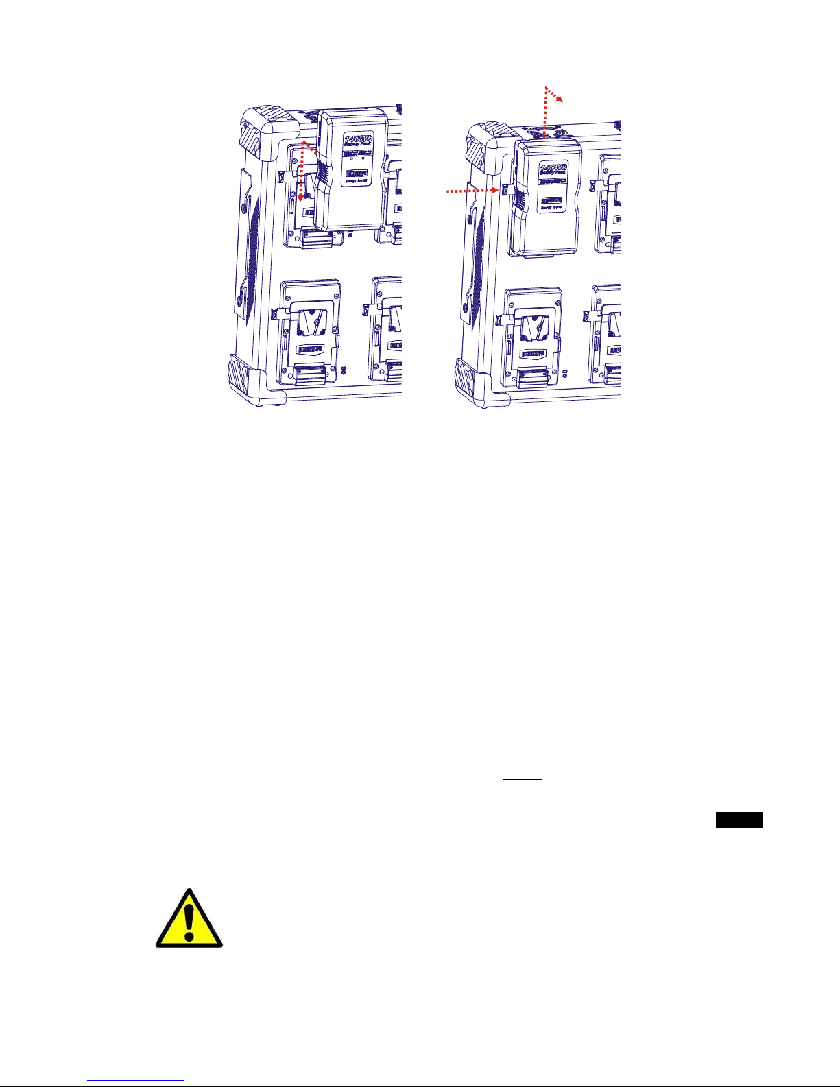
Battery installation Battery removal
CVS8XW CVS8XW
Insert the attery in the
direction of the arrow
1) Push and hold the utton in the direction of
the arrow
2) Pull out the attery in the direction of arrow
In the case when you want to charge more atteries, insert the
additional atteries into the availa le V-plate adapters.
In the case when an external equipment is plugged into any of the
two accessory XLRs, the charging process will e suspended only on
the related channels: #3 and #4, if connected to XLR of Bank-A; #7
and #8, if connected to that of Bank-B.
The AUX LED will light up and the paused attery LEDs will show
'WAITING'. Once the accessory has een unplugged, the charger will
resume the previous charging sequence and from the same point of
interruption.
PLEASE NOTE THAT THE MAXIMUM LOAD THAT CAN BE
CONNECTED TO ANY XLR OUTPUT MUST NOT EXCEED 110W.
ADDITIONAL SAFETY NOTES
Chargers and/or atteries may ecome hot during
charging. This is normal. Please consult your
BLUESHAPE dealer if you notice that either a
charger or a attery ecome excessively hot during
the charging operation.
Be careful not to lock the equipment’s ventilation
outlets.
Never insert any metallic or any other o jects inside
the equipment through the ventilation openings or
otherwise.
13

LCD indications and usage
Each LCD displays up to 2 pages of information divided as follows:
Bank-A Bank-B
page 1: details for Batteries 1~4
page 2: AUX port information
page 1: details for Batteries 5~8
page 2: AUX port information
To rowse etween the pages, press the 'CHAN' utton.
Pressing at anytime, the 'BACK' utton returns the user to the initial
page.
Page 1:
In these pages the information display show a summary of the
atteries in charge with these info always visi le:
- the attery state of charge in percentage
- the remaining charge time in minutes
- a ver ose indication of the attery status
Please note that when atteries other than BLUESHAPE are
installed, the information displayed may not e accurate.
B1: 55% 123m Charge
B2: no battery
B3: no battery
B4:100% - Full
B5: no battery
B6: no battery
B7: no battery
B8: no battery
Bank-A Bank-B
Pressing the 'INFO' utton permits a detailed view of each attery,
scrolling cyclically from 1 to 4 (for Bank-A) and from 5 to 8 (for Bank-
B). Pressing at anytime, the 'BACK' utton returns the user to the
previous screen. The picture elow shows a display example:
B1: 55% 123m Charge
V:15234mV I:4820m
T: 24C V12:3808-3815
N:134c V34:3799-3803
Explanation:
row #1
the attery state of charge in percentage
the remaining charge time in minutes
a ver ose indication of the attery status
row #2 V: Battery voltage
I: Charging current
row #3 T: Battery temperature
V12: Voltage of cell #1 and cell #2
row #4 N: Num er of charge/discharge cycles already elapsed
V34: Voltage of cell #3 and cell #4
If errors occur during charge, the explanation is given in the attery
detail page as descri ed in the following ta le.
14

Err # Explanation
01
Battery with wrong ID. Charge not allowed.
The attery has a wrong ID resistor (not in the range
10Kohm ~ 60Kohm) and is not ena led to charge.
02
Battery failure: the attery does not accept any charge.
A generic attery failure: It means that the charger was
expecting the attery to charge, ut it didn’t
Possi le reasons are:
1) a real attery failure in the attery:
- electrical failure: something is disconnected internally,
may e after a crash
- software failure: the attery has the safety settings locked
down and need to e reset ( y BSMON)
2) a temporary safety protection activated
3) the attery is almost full and the charger attempt to
charge it without success: in this case discharge the attery
a it more in order to start a new charging session.
The reason of the failure is usually descri ed on the charger
display
03
Battery Voltage too low. Charge is not allowed.
The pack voltage is elow 8V and is dangerous to attempt a
charge.
04
Timeout error in the charge session.
The attery does not terminated the charge in the expected
time. This error may occur charging pack with large
capacity. In this case simply remove the attery and install
again to reset the timer and start a new session until the
attery is full.
05
Premature charge termination. The charge process has
terminated unexpectedly.
This error means that the attery started charging ut
suddenly stopped.
It may e a temporary ina ility of the charger to charge, or
the attery went in to a temporary protection state. Perhaps
it could e that some cell has a voltage too high, and during
the charge process this would cause the pack protection
safety to trip in order to avoid dangerous overvoltage
conditions.
When this error occurs, the charge session is reset every
minute, and the charge is re-attempted.
This error occur also when a attery too hot (> 45°C) or too
cold (usually < 0°C) is inserted on the charger: in this case
the session does not stop ut the charger retry automatically
every 30 seconds until the attery allow charging.
15

Page 2
This page shows detailed information on the status of the AUX port -
the actual output voltage, the actual current and the power supplied
to the connected device if any.
The pictures elow show some display examples:
XLR Ouptut: ctive
Voltage: 13890 mV
Current: 2600 m
Power: 36 W
XLR Ouptut: Idle
Voltage: 13990 mV
Current: 0 m
Power: 0 W
Pressing the 'INFO' utton further details are shown:
BLUESH PE charger
Model: CVS8XW
Serial No: 15308
Fw: x.yy x.yy x.yy
Explanation:
row #2 Charger model
row #3 Serial num er
row #4 Firmware version for LCD control unit (1°) and charger
oards (2° and 3°)
16

Battery LED indications
# OPERATING MODE TIMEOUT LED INDICATION
1
BATTERY DETECTION
Battery detected while the other on
the same pair is already charging
BATTERY WAITING:
GREEN: 1sec ON/1sec OFF
2BATTERY NOT ALLOWED
10Kohm < ID resistor < 60Kohm
BATTERY NOT ALLOWED:
GREEN: 500ms/RED: 500ms
3
BATTERY EVALUATION
i) Total pack voltage <
8000mV
ii) I < 10mA
If the charging does not rise within
30sec, the battery does not accept
charge
iii) Single cell voltages < 2800mV
10mA < I < 50mA
iv) Single cell voltages > 2800mV
Total pack voltage < 13000mV
50mA < I < 300mA
3600sec
1200sec
VOLTAGE TOO LOW:
RED flashing
500ms ON/500ms OFF
BATTERY FAILURE:
Steady RED
PRECHARGE-1:
ORANGE flashing
500ms ON/500ms OFF
PRECHARGE-2:
ORANGE flashing
250ms ON/250ms OFF
4CONSTANT CURRENT MODE
13000mV < V < 16750, I = max 4.9A 18000sec CC-MODE:
Steady ORANGE
5
CONSTANT VOLTAGE MODE
V >16750mV
150mA < I < 4900mA
10800sec
CV-MODE:
ORANGE 500ms/
GREEN 500ms
6
FULL C ARGE
V 16800mV
I 150mA
FULL CHARGE:
Steady GREEN
7
OT ER INDICATIONS
In the case of premature charge
termination, the charger retries to
charge the battery every 30 seconds.
If after 10 minutes, there is still no
response, the indication is changed
into ‘BATTERY FAILURE’
PREMATURE CHARGE
TERMINATION:
RED: 250ms ON/100ms OFF /
250ms ON /1sec OFF
(2 blinks + 1 pause)
BATTERY FAILURE:
Steady RED
17

AUX output LED indications
# OPERATING MODE LED INDICATION
1The AUX output is correctly powered up:
10mA < I < 8.2A
AUX OK:
AUX LED Steady GREEN
2
The AUX is self-protected if a load is connected and an
excessive current is absorbed:
I > 8.2A
SHORT-CIRCUIT:
AUX LED Steady ORANGE
3
An Overload condition may occur when the AUX is
powered up and an excessive current is drained as
follow:
i) 8.2A < I < 9.5A, for 30sec
ii) 9.5A < I < 13A, for 1sec
iii) I > 13A
OVERLOAD1:
AUX LED+BAT2+BAT4
Steady RED
OVERLOAD2:
AUX LED Steady RED
OVERLOAD3:
AUX LED Steady ORANGE
18

Tec nical specifications
Type Constant current and voltage control system with timer
interventions
CC-MODE: Output current 4900mA ± 1%
CC-MODE: Vmax 16800 ± 50mV (0.3%)
CV-MODE: Vmax 16800 ± 50mV (0.3%)
CV-MODE: Cutoff current 150mA ± 10mA
Short circuit protection Available
Overcharge protection Available
Overtemperature protection Available
LEDS 3 colour type for BAT1~BAT8 and AUX
LCD 2x 20x4 Blue/White backlight
Special features IPCS and CTP
Auxiliary power 2x 13.8V 110W (max)
Power supply AC mains 100V - 240V ~, 47 - 63 z autoselect
Fuse 1 x 220V 2.5A (5x20mm quick blow) + 1 spare
Power consumption 200W max / 180W typical
Operating temperature range 0°C - 45°C
Storage temperature range -20°C - 65°C (-4°F - 149°F)
Dimensions 620 x 410 x 110 mm
Weight 9.7 Kg
The CE certification process is underway.
19

Notes concerning c arger usage wit BLUESHAPE battery
packs
It is recommended that the users always have at least another spare
attery readily availa le.
It is prefera le to charge atteries immediately efore use.
Some loss from self-discharge would result if the atteries are
charged several weeks in advance of their use. However, this slight
loss can e topped up at any time without any degradation of attery
performance (no memory effect)
It is recommended to store atteries in a cool and dry place. Charging
should e done at temperatures a ove 0°C and elow 45°C.
Slight heating of the attery is expected to occur during charge.
However if for some reason, the pack temperature reaches 60°C,
then the charge activity is suspended.
The pack resumes normal charging once the temperature drops ack
to elow 50°C. This is a safety feature incorporated in all
BLUESHAPE attery packs.
20
Other manuals for CVS8XW
1
Table of contents
Other Blueshape Batteries Charger manuals

Blueshape
Blueshape CGTR2P User manual

Blueshape
Blueshape CDT- 45 User manual

Blueshape
Blueshape CDT-60 User manual

Blueshape
Blueshape CVTR2 User manual

Blueshape
Blueshape CVS4XL User manual

Blueshape
Blueshape CVTR2 User manual

Blueshape
Blueshape CBS8XW User manual

Blueshape
Blueshape CVTR2PV User manual

Blueshape
Blueshape PWS2 User manual

Blueshape
Blueshape PWS4-48 User manual


