BMG Labtech FLUOstar Omega User manual

FLUOstar Omega
LUMIstar Omega
POLARstar Omega
SPECTROstar Omega
Operating Manual
Revision G

Omega Operating Manual BMG LABTECH
2/29 0415B0001G 2014-05-16
Omega Family of Readers
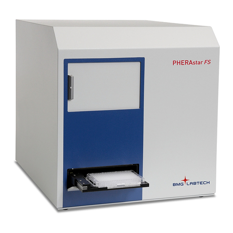
The FLUOstar Omega is a multifunctional microplate reader that supports a wide variety of applications and
the following reading modes: fluorescence intensity, time-resolved fluorescence, absorbance and
luminescence.
The POLARstar Omega can measure in the same modes as the FLUOstar, as well as in fluorescence
polarization mode with simultaneous dual emission.
The LUMIstar Omega is a luminescence microplate reader that can be upgraded to include all of the above
mentioned modes.
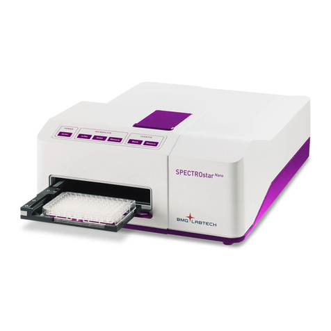
The SPECTROstar Omega is an absorbance microplate reader that can be upgraded to include all of the
above mentioned modes.
The versatile optical system allows easy switching from top to bottom optic.
All Omega instruments achieve high-performance measurement data in a wide range of wavelengths.
Additionally, the instruments have a built-in incubator and can be configured with up to two reagent injectors.
FLUOstar Omega
Manufacturer: BMG LABTECH GmbH
Allmendgrün 8
77799 Ortenberg
Germany
www.bmglabtech.com
support@bmglabtech.com
+49-781-969680
Copyright 2007-2014 BMG LABTECH. All rights reserved. All BMG LABTECH brand and product names are trademarks of BMG
LABTECH. Other brand and product names are trademarks or registered trademarks of their respective holders.

BMG LABTECH Omega Operating Manual
2014-05-16 0415B0001G 3/29
This manual is designed to guide FLUOstar Omega, POLARstar Omega, LUMIstar Omega and
SPECTROstar Omega users through the basic hardware features of the instrument.
Although these instructions were carefully written and checked, we cannot accept responsibility for problems
encountered when using this manual. Suggestions for improving this manual will be gratefully accepted.
BMG LABTECH reserves the right to change or update this manual at any time. The Revision Number is
stated at the bottom of every page.
For contact information please visit www.bmglabtech.com or send an email to germany@bmglabtech.com.
Disclaimer note:
The information contained in this documentation is subject to change without notice. BMG LABTECH GmbH
shall not be liable, to any extent whatsoever, for any damages resulting from or arising out of the use or
performance of this system and related documentation or the procedures specified in this manual, regardless
of foreseeability or the form of action, whether in contract, tort (including negligence), breach of warranty,
strict liability or otherwise, and including but not limited to damages resulting from loss of data, loss of
anticipated profits, or any special, indirect, incidental or consequential damages. BMG LABTECH GmbH is
not responsible for any damage to this equipment or personal injury that may result from the use of this
equipment or of an accessory not manufactured by BMG LABTECH GmbH. The user assumes full
responsibility for the results obtained from the use of this system and related documentation and for
application of such results.

Omega Operating Manual BMG LABTECH
4/29 0415B0001G 2014-05-16
TABLE OF CONTENTS
1TECHNICAL SPECIFICATIONS 5
2SAFETY INFORMATION 7
2.1 DESCRIPTION OF WARNINGS 7
2.2 GENERAL INFORMATION 7
2.3 ENVIRONMENTAL SAFETY STANDARDS 8
2.4 ELECTRICAL SAFETY 8
2.5 PHOTOBIOLOGICAL SAFETY 8
2.6 CHEMICAL AND BIOLOGICAL SAFETY 9
2.7 CLEANING AND INSTRUMENT DISINFECTION 9
3INSTALLATION 12
3.1 TRANSPORT LOCK 12
3.2 SOFTWARE INSTALLATION 13
3.3 POWER AND COMMUNICATION CONNECTIONS 13
4INSTRUMENT OVERVIEW 14
5DESCRIPTION OF COMPONENTS 16
5.1 OPTICS 16
5.2 INSTALLATION AND CHANGING OF OPTICS 16
5.2.1 FLUORESCENCE INTENSITY OPTICS 17
5.2.2 LUMINESCENCE OPTICS 17
5.2.3 FLUORESCENCE POLARIZATION OPTICS 18
5.2.4 DUAL EMISSION OPTICS 18
5.2.5 COMBINATION OPTICS 18
5.2.6 ABSORBANCE OPTICS 19
5.2.7 HIGH DENSITY OPTICS 19
5.2.8 BOTTOM OPTICS 19
5.2.9 ADVANCED OPTIC HEAD FOR TRF /TR-FRET 20
5.3 FILTERS 24
5.3.1 FILTER CHANGE AND INSTALLATION 24
5.3.2 FLUORESCENCE FILTERS 26
5.3.3 FLUORESCENCE POLARIZATION FILTERS 26
5.3.4 DUAL EMISSION FILTERS 26
5.3.5 ABSORBANCE FILTERS 26
5.3.6 LUMINESCENCE FILTERS 26
5.4 SPACERS 27
5.5 REAGENT INJECTORS 28
5.6 FAN COVER 29

BMG LABTECH Omega Operating Manual
2014-05-16 0415B0001G 5/29
1 Technical Specifications
Measurement principles
FLUOstar Omega: - Fluorescence intensity
- Time-resolved fluorescence – TR-FRET (opt.)
- Luminescence (opt.)
- UV/VIS absorbance spectra
- AlphaScreen® / AlphaLISA®(opt.)
- Upgradeable to POLARstar Omega
LUMIstar Omega: - Luminescence
- Simultaneous dual emission luminescence (opt.)
- Upgradeable to FLUOstar / POLARstar Omega
POLARstar Omega: - Fluorescence polarization
- Fluorescence intensity
- Simultaneous dual emission fluorescence
- Time-resolved fluorescence – TR-FRET (opt.)
- Luminescence (opt.)
- Simultaneous dual emission luminescence (opt.)
- UV/VIS absorbance spectra
- AlphaScreen®/ AlphaLISA®(opt.)
SPECTROstar Omega: - UV/VIS absorbance spectra
- Upgradeable to FLUOstar / POLARstar Omega
Light source
FLUOstar, POLARstar & SPECTROstar Omega: High-energy xenon flash-lamp
Detector - Side window photomultiplier tube
Filters
FLUOstar & POLARstar Omega: - 2 filter wheels with 8 excitation and 8 emission filter positions
LUMIstar Omega: - Emission filter wheel with 8 filter positions
Gain control - Software selectable gain
- Automatic gain adjustment
Plate carrier - Auto lock microplate carrier
- All microplate formats up to 1536-well -
Microplates should fulfill the SBS specification and non-SBS formats
should fit: (lxwxh) (mm) max: 128x86x22; min. length 124
Reagent Injection - Up to two built-in reagent injectors
- Individual injection volumes for each well
- Injection volumes definable down to 3µl
- Up to 4 independent injection actions per well
- Variable injection speed (100 µl/s to 420 µl/s)
Shaking - Linear, orbital and double-orbital shaking
- User-definable time and speed
Incubation - Incubation range from ambient +4°C to 45°C, in 0.1°C steps
- Extended incubation up to 65°C (optional)
- Temperature monitoring (without incubation)
- Temperature stability 0.2°C
Fluorescence intensity - Limit of detection 0.2 fmol / well fluorescein
- Spectral range (ex. and em.): 240 ... 740 nm (900 nm opt.)
- Dynamic range 8 decades
Time-resolved fluorescence - Limit of detection 30 amol / well europium
- Advanced TRF/TR-FRET: 3 amol / well europium
- Spectral range (ex. and em.): 240 ... 740 nm (900 nm opt.)
- Dynamic range: 6 decades

Omega Operating Manual BMG LABTECH
6/29 0415B0001G 2014-05-16
Luminescence - Limit of detection 20 amol / well ATP
- Spectral range 240 ... 740 nm
- Dynamic range: 9 decades
Fluorescence polarization - Limit of detection: <5 mP SD at 1 nM fluorescein
- Spectral range: (ex. and em.): 380 ... 740 nm (900 nm opt.)
- Dynamic range: 4 decades
Absorbance Spectrometer based - Spectral range 220 ... 1000 nm
- Full spectrum captured in < 1 s/well
- Selectable spectral resolution: 1 nm, 2 nm, 5 nm, 10 nm
- OD range: 0 to 4 OD
- Accuracy: < 1% at 2 OD
- Precision: < 0.5% at 1 OD and < 0.8% at 2 OD
AlphaScreen®- Limit of detection: < 100 amol / well (384)*
- AlphaScreen®and AlphaLISA®possible
Computer interface - USB 2.0 or USB 3.0
Power requirements - 100-240 V, 50/60 Hz, max peak 300 VA
- Consumption:
Instrument off: 0 W
Normal operating conditions: 25 W
Normal operating conditions, incubation set to 37oC: 60 W
- Fuses: T5A/250V (use original spare fuses provided by BMG
LABTECH only)
Dimensions - Height: 31 cm, width: 44 cm and length 48 cm
Weight - 29 kg
Ambient conditions - Operating temperature: 15°C to 35°C
- Storage temperature: -10°C to 50°C
- Humidity of atmosphere: 20% to 80%
- Non-condensing
Instrument conformity - Over voltage category II; contamination class II; protection class I
Options - Stacker for 50 microplates and optional barcode reader
- ACU: Atmospheric Control Unit to regulate both O2(1-19%) and
CO2(0-20%) inside the microplate chamber
- Gas Vent: Passive purge gas vent to replace the atmosphere in the
microplate chamber
- Fan Cover: improved control of microplate ambient conditions,
especially for long- term incubation experiments
- LVis Plate with 16 low volume microspots (2µL) for e.g. DNA
concentration measurements
- LVis Plate with additional absorbance quality control standards
(approximate values of 0.1, 0.3, 0.6 and 1.0 OD); one holmium oxide
filter for wavelength accuracy
Limit of detection was calculated according to the IUPAC standard: 3 x (SDblank)/slope
* Limit of detection < 100 amol of biotinylated and phosphorylated polypeptide (P-Tyr-100 assay kit,
PerkinElmer, #6760620C), measured in white 384 small volume microplates (17 µL/well)
AlphaScreen®and AlphaLISA®are registered trademarks of PerkinElmer, Inc.
Specifications are subject to change without notice.

BMG LABTECH Omega Operating Manual
2014-05-16 0415B0001G 7/29
2 Safety Information
2.1 Description of Warnings
The warning signs used throughout this manual adhere to the description set forth in DIN 4844-2.
A general warning calls attention to a condition which is further described and must be strictly
followed by the operator.
Warning for optical radiation
2.2 General Information
This instrument must be installed and used as outlined in this Operating Manual.
Installation, service and any operation which requires opening of the instrument must be
performed only by trained and certified personnel from BMG LABTECH. Failure to comply
with these instructions will invalidate the warranty and can lead to unsafe operation of this
equipment.
The area designated for the instrument should be free of dust, liquids and acidic vapor. The
surface of the table should be flat and even. Avoid areas subject to vibrations and direct
sunlight.
Prior to turning on the instrument the first time, let the instrument adapt to room temperature
for at least 3 h to avoid condensation which can cause a short circuit. BMG LABTECH will
void the warranty if damage occurs to electrical and/or mechanical parts in cases where the
instrument was turned on before the recommended accommodation time.
Handling and operation of the equipment must be carried out only by qualified personnel and
staff trained by an official BMG LABTECH representative.
Microplates and related accessories (e.g. LVis Plate) operated at temperatures higher than
55°C must cool down below 55°C before being handled and removed from the instrument.
Samples and reagents, be it in solid, liquid, or gaseous form, must be removed from the
instrument immediately after measurement to avoid corrosion and accumulation of hazardous
substances inside the instrument.

Omega Operating Manual BMG LABTECH
8/29 0415B0001G 2014-05-16
2.3 Environmental Safety Standards
The environmental safety standards for operation under norm IEC 61010-1 are met under the following
conditions:
•Indoor use (adhere to the Occupational Exposure Limit Values for ECM, UPS, vibration, and sunlight
when setting up the instrument in the laboratory)
•Altitude (up to 2000 m)
•Temperature (+15oC to +35oC)
•Relative Humidity (Maximum 80% at 31oC non condensing then decreasing linearly to 50% at 40oC)
•Mains supply voltage fluctuation (+/- 10%)
•Overvoltage category (II) acc. to IEC 60364-4-443
•Pollution degree (2) acc. to IEC 61010-1
2.4 Electrical Safety
•Connect the unit only to a grounded supply socket. The instrument is class 1 construction and must
be grounded.
•Connect the unit only to a power supply with a designated voltage rating corresponding to the label
on the back of the instrument.
2.5 Photobiological Safety
This instrument is rated in the free group as RG 0, according to the IEC 62471-2 photobiological safety of
lamps and lamp systems. The intended and routine use of this equipment and its high power xenon flash
lamp does not pose a photobiological hazard, given that the user strictly follows these precautions:
Do not operate the instrument unless the instrument shell is mounted and all screws are in
place and tightened.
Do not open the flap door of the microplate carrier during a measurement run.
Do not open the reagent door during a measurement run.
Do not disconnect a light guide during a measurement run.
Do not look directly into a disconnected light guide during a measurement run.

BMG LABTECH Omega Operating Manual
2014-05-16 0415B0001G 9/29
A measurement run is indicated by a blinking green LED on the instrument.
The following light source is incorporated and encapsulated in the BMG LABTECH ‘Omega’ microplate
reader instrumentation:
Xenon high power flash lamp – emits ultraviolet light during operation at levels that could
injure the eyes or skin. Do not look directly at the light and avoid exposing any skin to the
light. During normal operation the user will not be exposed to any light from the xenon flash
lamp.
2.6 Chemical and Biological Safety
Daily routine use with this instrument may involve the handling and use of compounds that are toxic,
flammable, or biologically harmful. When working with materials and compounds as stated, make sure to
observe the following precautions:
•Handle all samples, be it liquid, solid, or in gaseous form according to good laboratory practice.
•Adhere to the maximum workplace concentration (MAC) and to laboratory safety regulations (e.g.
BGI 850-0, formerly BGR120 in Germany).
•Wear safety goggles as the spilling of liquids may occur.
•Contact your safety officer to dispose of hazardous waste solutions and when working with
flammable liquids.
The microplate reader must not be exposed for any length of time to chlorinated hydrocarbons at high
concentration (i.e., chloroform, aromatic hydrocarbons, such as toluene or benzene, etc.) or to acetone. All
warranties are void if the instrument comes in contact with organic solvents.
If using any of these substances while performing a measurement, be sure to remove the sample
immediately after measurement is completed. If evaporation of any of these substances occurs inside the
instrument, it is important to vent the instrument for a sufficient amount of time by opening the lid and placing
the microplate carrier in the plate out position with the flap door open.
Gas vent connection – for the standard gas purge vent use a regulator followed by a flow
restrictor to set the flow rate. The instrument should be housed in an atmospheric gas tight
bag (e.g. Aldrich® AtmosBag, Z530220-1E) to prevent spillage of gas.
Use only mild detergent or 70% ethanol for cleaning the instrument. Make sure the instrument
is always in the OFF position for cleaning and servicing.
2.7 Cleaning and Instrument Disinfection
Please follow all instructions carefully for a successful disinfection of this instrument.
All parts of the instrument that have the possibility of contacting patient sera or positive samples must be
handled as if they are hazardous. For this reason, it is recommended that gloves be worn while maintaining
or working with the instrument.
It is very important that the instrument is thoroughly disinfected before maintenance or before removing the
instrument from the laboratory. Be sure that the instrument is disinfected before you send it to your distributor
or to the manufacturer. For safety reasons, you have to fill out the Disinfection Certificate, or the instrument
may not be accepted by the service center or by customs authorities.
Use suitable disinfectants, e.g. Alcohol (70%).
Authorized personnel wearing disposable gloves and protective clothing should only perform the disinfection
procedure. The location should be well ventilated.

Omega Operating Manual BMG LABTECH
10/29 0415B0001G 2014-05-16
Disinfection Steps
1. Disconnect the instrument from the main power supply.
2. Remove the USB cable from the connector.
3. Clean all outside surfaces of the instrument carefully with cotton wool, which has been soaked in
disinfecting solution.
4. Place the instrument in a large plastic bag along with the cotton wool that has been soaked in
disinfecting solution. Ensure that the wool does not touch the instrument.
5. Close and seal the bag.
6. Keep the instrument in the plastic bag for at least 24 hours.
7. After the disinfection time has lapsed, remove the instrument from the plastic bag and clean all outside
surfaces of the instrument with cotton wool that has been soaked in alcohol solution.
8. Repeat the procedure for disinfection on any accessories, which will be returned with the instrument.
9. Complete the Disinfection Certificate

BMG LABTECH Omega Operating Manual
2014-05-16 0415B0001G 11/29
Disinfection Certification
This instrument and its inventory have never been in contact with any
dangerous biological material, or if so, the instrument and its inventory have
been disinfected according to the instructions of the operating manual of the
instrument.
Name: ________________________________________________
Company:
________________________________________________
________________________________________________
________________________________________________
________________________________________________
Date, Signature: ________________________

Omega Operating Manual BMG LABTECH
12/29 0415B0001G 2014-05-16
3 Installation
When moving the Omega reader, it is recommended that two people lift the instrument together
to avoid personal injury. Be sure to lift the instrument from the bottom and both to avoid injury
and/or damage to the instrument. The operator of the Omega microplate reader is assumed to
be trained in the correct operation of the instrument and the safety issues.
When unpacking the instrument, please check to ensure that all of the following parts are included:
•FLUOstar Omega or LUMIstar Omega or POLARstar Omega or SPECTROstar Omega reader
•Control and MARS Data Analysis software (CD ROM in a cover inside this manual)
•Manual
•Power cord
•USB cable
•Service box containing: - Allen key (1.5mm)
- 2 extra fuses: 5A/250V for main power 100V-240V
- 4 spacers
- Injector needle cleaner (only with instruments that have reagent
injectors)
Call BMG LABTECH immediately if any of these items are missing.
The area designated for the instrument should be free of dust, liquids and acidic vapours. The table's surface
should be flat and even. Avoid areas subject to vibrations and direct sunlight.
After unpacking and positioning the reader, please do the following steps in the given order:
1 – Release transport lock
2 – Install software
3 – Plug in power and USB connection
Always install the software before plugging in USB connection
3.1 Transport Lock
When the instrument is shipped or moved to a different location, the transport lock should be in the locked
position.
The transport lock is located in the back left corner of the reagent box (figure 1 and figure 6). Once the
instrument is in its permanent location, the transport pin should be unlocked to free the plate carrier. To do
this turn the transport pin counter-clockwise until it is moved up by the spring.
Figure 1: Left: transport lock in locked position (screw is down).
Middle: transport lock in unlocked position (screw is up).
Right: the groove where the transport pin can lock the plate carrier
LOCKED POSITION
(screw is down)
UNLOCKED
(screw is up)
The groove where the transport
lock fixes the plate carrier view)

BMG LABTECH Omega Operating Manual
2014-05-16 0415B0001G 13/29
If the instrument needs to be moved to a new location, the plate carrier should be in the locked position
otherwise the transport system could be damaged.
Figure 2: Plate In / Plate Out button
Press and hold the plate in / plate out button for 3 seconds, hereafter the plate carrier will automatically move
to its lock position. Once the reader is switched off, the transport pin can be moved down and turned
clockwise. The transport pin must be screwed until it tightens. Please tighten it firmly with your fingers. Don’t
use any tools.
The transport system is locked when the transport lock is in its down position and firmly tightened.
3.2 Software Installation
Before connecting the instrument's USB communication cable the software must be
installed! Please follow the instructions in the software manual
3.3 Power and Communication Connections
•Power Connection
First check that the power switch on the back of the instrument is in the ‘Off’ position. Inspect the voltage
information on the label next to the power switch to ensure that it corresponds to the local main power
specifications. Also make sure the power cable is grounded. Hereafter, the power cable can be connected to
the instrument.
•USB Communication Connection
Connect the USB cable to the FLUOstar Omega (or POLARstar Omega or SPECTROstar or LUMIstar
Omega) and to the USB port on the PC. Please connect the reader directly to your PC and do not use a
USB-hub.
Only connect a computer that corresponds to EN 60950 and UL 1950 for data processing
instruments.
You can perform a connection check within the setup menu of the Omega software (go to ‘Settings |
Connection’ and click ‘Connection check’).
If the instrument and PC are communicating, a ‘Connection OK’ message will appear.
Figure 3: Connection window

Omega Operating Manual BMG LABTECH
14/29 0415B0001G 2014-05-16
Reagent box
Plate carrier
Plate In / Plate Out button
4 Instrument Overview
Front View
Figure 4: FLUOstar Omega
A constant green light means the instrument is turned on. A flashing green light means the instrument is
busy (e.g. performing a measurement, plate in/out, priming, etc.). A faster flashing green light (5 flashes per
second) means an error has occurred.
Back View
Figure 5: Back view of reader
Instrument turned on/busy light
USB
connection
Stacker
connection
Power cable
connection
On/Off
switch
Serial
number
415-1336

BMG LABTECH Omega Operating Manual
2014-05-16 0415B0001G 15/29
Top View, Reagent Box
Figure 6: FLUOstar Omega & POLARstar Omega top view of reagent box with
spectrometer based absorbance and 2 reagent injectors; no top optic is installed
Filter wheel cover
(for emission filter wheel and
excitation filter wheel)
Transport lock
Reagent injectors (optional)
Measurement
head position
Bottom optic
Absorbance optic
Injection needle holder

Omega Operating Manual BMG LABTECH
16/29 0415B0001G 2014-05-16
Emission no. 2
(available in
POLARstar
Omega)
5 Description of Components
5.1 Optics
All readers are equipped with standard UV/Vis optics for top reading. For the Omega, there are different top
reading optics available for fluorescence intensity, fluorescence polarization, luminescence, absorbance and
time-resolved fluorescence.
5.2 Installation and Changing of Optics
The Omega readers are equipped with quick-fix mountings (figure 7), allowing for the easy exchange of
optics and placement of position spacers (for more about spacers see 5.4). No tools are required for
changing the optics. Remove the optic from the positioning wheel (figure 8) by hand and turn the holders on
the measurement head frame to release the black mounting piece of the optic.
Figure 7: Quick-fix - pull up and turn to change optic
Always hold the optics by the black mounting piece
Figure 8: Filter wheel cover with positioning wheels
Quick-fix: in fixed position
Quick-fix: in released position
Emission
positioning wheel
Excitation
positioning wheel

BMG LABTECH Omega Operating Manual
2014-05-16 0415B0001G 17/29
5.2.1 Fluorescence Intensity Optics
The fluorescence intensity and time-resolved fluorescence light guides are silver in color, liquid-filled and
come connected to the excitation and emission positioning wheels. The yellow marked light guide routes the
excitation light to the sample while the blue marked light guide routes the emission light to the detector.
In addition, the Fluorescence Intensity Optic can be used to measure luminescence. To do so the emission
light guide is used to route the light from the sample to the detector. The luminescence option is of courses
needed for reading luminescence.
If the AlphaScreen option is present, this optic can be used to detect AlphaScreen.
To position the measurement head with the holders, see chapter 5.2 Installation and Changing of Optics.
If the reagent injection option is present, be careful when positioning the needles in the measurement head
(see figure 10) in order to avoid damage to the reagent needles and to the optic.
Figure 9: Fluorescence intensity optic Figure 10: Holes to position reagent needles in the
measurement head
5.2.2 Luminescence Optics
The Luminescence Optics are important for LUMIstar Omegas, but
can also be used in FLUOstar or POLARstar Omegas. The
luminescence optic has one light guide, which is silver in color. The
light guide connects to the emission side. To position the
measurement head with the holders, see chapter 5.2 Installation and
Changing of Optics.
There are two dedicated luminescence optics: a 3 mm diameter light
guide that is used for plates up to 96-wells, and a 2 mm diameter light
guide that is used for plates up to 384-wells.
For reading luminescence, the luminescence option needs to be
present in the FLUOstar or POLARstar Omega.
Figure 11: Luminescence optic

Omega Operating Manual BMG LABTECH
18/29 0415B0001G 2014-05-16
5.2.3 Fluorescence Polarization Optics
The light guides for fluorescence polarization are black and form a triangle at the
base of the optic.
Position the light guides as follows: right light guide into excitation position, left
light guide into the upper emission position (PMT 1) and the center light guide
into the lower emission position (PMT 2).
Only the POLARstar Omega can measure fluorescence polarization. It is
possible to upgrade the FLUOstar Omega to a POLARstar Omega.
Regarding filters for fluorescence polarization see chapter 5.3.3.
5.2.4 Dual Emission Optics
The dual emission optics are designed for assays in which you excite at one wavelength and measure two
emission wavelengths simultaneously (i.e. FRET). This is only possible in the POLARstar Omega because
this action requires two PMT's. The dual emission optics look like polarization optics, but are not capable of
polarization. The optic has to be installed in the same way as the polarization optic (figure 12).
5.2.5 Combination Optics
This optic can only be used with readers with PMT based absorbance, not with
spectrometer based absorbance.
The combination optic is made up of two liquid-filled light guides for fluorescence
intensity or luminescence and a quartz fiber for absorbance measurement (figure
13). It can be used for plate formats up to 96-well.
To position the measurement head with the quick-fix holders, see chapter 5.2
Installation and Changing of Optics.
For fluorescence measurements: excitation enters through the yellow marked light
guide and emission is measured through the blue marked light guide.
For absorbance measurements: The gray, red marked, absorbance light guide
excites from above and the absorbance is measured through the bottom optic.
In addition, for reader which have the luminescence option available,
luminescence can be measured through the blue marked light guide.
Figure 13: Combination optic
Regarding reagent injection: be careful when you position the needles in the measurement head (see figure
14) to avoid damage to the reagent needles as well as to the optic. The optional reagent injectors need to be
available.
Figure 14: Holes to position reagent needles in the measurement head
Figure 12: fluorescence
polarization optic

BMG LABTECH Omega Operating Manual
2014-05-16 0415B0001G 19/29
5.2.6 Absorbance Optics
This optic can only be used with readers with PMT based absorbance, not with
spectrometer based absorbance.
There is an optimized optic for absorbance mode available (see figure 15). This
optimized absorbance optic can be used for plate formats up to 384-well. The light
guide connects to the red-marked excitation-positioning wheel. This optic does not allow
for the use of injectors.
You can also use the combination optic (see chapter 5.2.5).
Figure 15:
Optimized
absorbance optic
5.2.7 High Density Optics
The high-density optic has one excitation light guide surrounded by six emission light
guides. This optic is designed to minimize cross-talk in plate formats such as 384-
and 1536-well plates.
To position the measurement head with the quick-fix holders, see chapter 5.2
Installation and Changing of Optics.
The single black light guide connects to the yellow-marked position of the excitation
wheel. The six-bundled light guides are inserted into the blue-marked position of the
emission wheel.
To measure 1536-well plates the reader has to be prepared specially.
Injection is not possible into 1536 well plates.
Figure 16: High
density optic
5.2.8 Bottom Optics
The bottom optics are used to measure fluorescence, luminescence and absorbance. The bottom optics
enter the reagent box on the left side and are connected to the left position of the excitation and emission
wheels.
Figure 17: Principle drawing of top
and bottom optics

Omega Operating Manual BMG LABTECH
20/29 0415B0001G 2014-05-16
5.2.9 Advanced Optic Head for TRF / TR-FRET
The Advanced Time-Resolved-Fluorescence (TRF) – Optic Head is an upgrade option for the FLUOstar
Omega and POLARstar Omega microplate readers. It is based on an innovative optical system using a lens
and z-adjustment to direct the excitation light to the optimal focal point in the center of a well.
Emission Light Guide (blue)
Excitation Light Guide
(yellow)
Lens (DO NOT TOUCH)
Indentation for Quick Fix holder
Figure 18: The TRF- optic head with excitation and emission light guides
Knob for adjusting
the z-height of the lens
Scale displaying z-height
above well bottom (mm)
Figure 19: The TRF- optic head with z-height adjustment
Installation:
NOTES:
1. Before installing the TRF-optic head make sure to install the supplied filters for TRF measurement as
described in 4.3.1 ‘Filter Change and Installation’.
2. Make sure that the firmware of your Omega reader is at least v.1.12. The firmware version can be
read by opening the Control software and clicking on the reader icon in the upper right corner.
Contact BMG LABTECH in case you need an update of the reader firmware
(support@bmglabtech.com).
This manual suits for next models
3
Table of contents
Other BMG Labtech Laboratory Equipment manuals
Popular Laboratory Equipment manuals by other brands
Teledyne
Teledyne AutoInjector Module Installation and operation guide
Fast Mover
Fast Mover FMT9000 instruction manual
HEKA
HEKA Favorit-Olymp 128 operating manual

OHAUS
OHAUS Frontier 2000 Series instruction manual

vacuubrand
vacuubrand PC 510 NT Instructions for use

Thermo Scientific
Thermo Scientific HyPerforma 5.1 S.U.B. Hardware Integrator Guide
